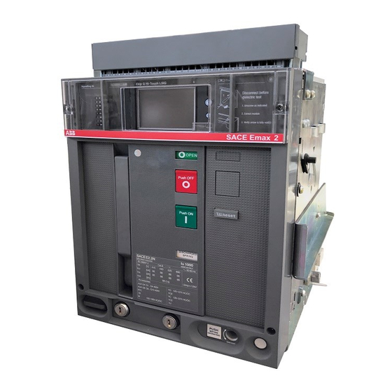
ABB Emax 2 Bedienungsanleitung
Nachrüstung zwischen steckbarer leistungsschaltern
Vorschau ausblenden
Andere Handbücher für Emax 2:
Emax 2
DOC. N° 1SDH001560R0001 - ECN000103165 - Rev. D
Retrofitting tra interruttori Estraibili Emax 2 e Megamax F5-F6.
Retrofitting between Emax 2 and Megamax F5-F6 Withdrawable circuit-breakers.
Nachrüstung zwischen Steckbarer Leistungsschaltern Emax 2 und Megamax F5-F6.
Reconfiguration entre disjoncteurs Débrochables Emax 2 et Megamax F5-F6.
Retrofitting entre interruptores Extraíble Emax 2 y Megamax F5-F6.
Il presente kit di retrofitting, è costruito per la sostituzione totale di interruttori
aperti estraibili Megamax F5-F6 con interruttori aperti in esecuzione estraibile
di più moderna fattura tipo Emax 2 di medesima taglia, senza dover eseguire
alcuna modifica alle parti attive del quadro.
E' garantita la totale corrispondenza delle caratteristiche elettriche (corrente
nominale e potere di interruzione) a condizione che
1.La scelta sia effettuata in conformità a quanto riportato nei cataloghi tecnici
relativi ai prodotti di retrofitting.
2.L'interruttore Megamax da sostituire sia installato in conformità al proprio
manuale di installazione, rispettando le distanze di isolamento verso massa, il
dimensionamento delle sbarre di connessione, il posizionamento del primo
setto di ancoraggio.
IMPORTANTE
L'attività di retrofitting consente una sostituzione di un dispositivo di comando
e protezione divenuto obsoleto ma non di alterare in maniera alcuna i dati di
progetto originali del quadro esistente. Qualora il nuovo interruttore
presentasse dati di targa superiori, i kit di retrofitting sono dimensionati per le
prestazioni del vecchio dispositivo.
Verificare la dimensione effettiva della cella prima di procedere all'acquisto.
Per le dimensioni vedere questo manuale.
Per ulteriori chiarimenti contattare ABB.
Attenzione Istruzioni riguardanti il solo assemblaggio del kit di retrofitting,
non sono da intendersi come sostitutive del manuale di installazione, uso e
manutenzione del nuovo interruttore Emax 2.
Cablare i circuiti ausiliari del nuovo interruttore secondo lo schema elettrico
Emax 2 documento 1SDM000105R0001.
MESSA IN SICUREZZA DELL'IMPIANTO
A) A garanzia dell'incolumità del personale addetto all'installazione del kit,
prima di operare la sostituzione dell'interruttore, si raccomanda di seguire,
scrupolosamente, le seguenti azioni:
- Mettere fuori servizio il quadro ospitante
- Portare l'interruttore da sostituire in posizione di aperto e molle scariche
- Disconnettere le applicazioni ausiliarie
- Prima di estrarre l'apparecchio, controllare nuovamente il fuori servizio
dell'utenza
B) Smantellare completamente il vecchio interruttore conservando le viti di
connessione dei poli del vecchio interruttore Megamax alla barratura del
quadro.
This retrofitting kit allows withdrawable Megamax F5-F6 circuit-breakers to be
fully replaced with the more modern Emax 2 plug-in air circuit-breakers of the
same size without having to modify the live parts of the switchgear in any way.
Full correspondence of the electrical characteristics is guaranteed (rated
current and breaking capacity) so long as:
1.The kit is chosen in accordance with the indications in the technical
catalogues dedicated to retrofitting products.
2.The Megamax circuit-breaker to be replaced has been installed in
compliance with the instructions in the relative installation manual, and with
the specified insulation clearance towards earth, connection busbar size and
position of the first anchor plate.
IMPORTANT
Retrofitting allows an obsolete control and protection device to be replaced,
but does not allow the data of the original project of the existing switchboard to
be altered in any way.
If the rating plate data of the new circuit-breaker are higher, the retrofitting kits
are sized for the performance of the old device.
Verify the actual size of the cell before purchasing.
For the dimensions see this manual.
Consult ABB for further details.
Warning The instructions concern the sole assembly of the retrofitting kit.
They do not substitute the instructions in the installation, operation and
maintenance manual of the new Emax 2 circuit-breaker.
Wire auxiliary circuits of new circuit-breaker as shown in Emax 2 circuit
diagram, document 1SDM000105R0001
SETTING THE INSTALLATION IN SAFE CONDITIONS
A) To ensure that the persons who install the kit work in safe conditions, strictly
comply with the following instructions before replacing the circuit-breaker:
- Close down the switchboard in which the circuit-breaker is to be installed.
- Set the old circuit-breaker to the open position with the springs unloaded.
- Disconnect the auxiliary circuit applications.
- Check to make sure that the user is disconnected before removing the
device.
B) Completely disassemble the old circuit-breaker, but keep the screws that
connect the poles of the old Megamax circuit-breaker to the switchboard bars.

Verwandte Anleitungen für ABB Emax 2


Inhaltszusammenfassung für ABB Emax 2
- Seite 1 This retrofitting kit allows withdrawable Megamax F5-F6 circuit-breakers to be aperti estraibili Megamax F5-F6 con interruttori aperti in esecuzione estraibile fully replaced with the more modern Emax 2 plug-in air circuit-breakers of the di più moderna fattura tipo Emax 2 di medesima taglia, senza dover eseguire same size without having to modify the live parts of the switchgear in any way.
- Seite 2 Änderung an conception plus moderne type Emax 2 de même tipo Emax 2, del mismo tamaño, sin tener que den aktiven Teilen der Schaltanlage vornehmen taille, sans devoir effectuer aucune modification modificar ninguna parte activa del cuadro.
- Seite 3 Megamax F5 3200A HR W => E4.2 4000A W III IV III IV III IV III IV III IV III IV III IV 13x28 8,4x17 6,4x12,5 III IV III IV M8 x 25 III IV III IV III IV M8 x 16 M8 X 55 M12 x 85 M6 x 12...
- Seite 4 Megamax F5 4000A HR W => E4.2 4000A W III IV III IV III IV III IV III IV III IV M8 X 55 M8 x 25 M12 x 70 13x24 M8 x 45 M8 x 16 8,4x17 M12 x 90 M6 x 12 6,4x12,5 III IV...
- Seite 5 Megamax F5 4000A VR W => E6.2 4000A W III IV III IV III IV III IV III IV III IV III IV 13x28 13x24 10,5x22 8,4x17 6,4x12,5 III IV M8 x 25 III IV III IV III IV III IV III IV M8 x 16 M6 x 12...
- Seite 6 M6 x 12 F5-F6 ATTENZIONE! La sequenza di montaggio a seguire è quella proposta da ABB, ma può essere variata a cura del cliente, in funzione delle dimensioni e dell’accessibilità del quadro. WARNING! The required assembly sequence is the one proposed by ABB, but the customer can change it to suit the size and accessibility of the switchgear.
- Seite 7 Megamax F5 3200A HR W => E4.2 4000A W Not Supplied - Installare le sbarre sul quadro usando le viti di connessione dei poli del vecchio interruttore (non fornite nel kit). Non fissare le viti. - Install the busbars on the switchboard using the poles connecting screws of the old circuit-breaker (not supplied in the kit).
- Seite 8 Megamax F5 3200A VR W => E4.2 3200A W Not Supplied - Installare le sbarre sul quadro usando le viti di connessione dei poli del vecchio interruttore (non fornite nel kit). Non fissare le viti. - Install the busbars on the switchboard using the poles connecting screws of the old circuit-breaker (not supplied in the kit).
- Seite 9 Megamax F5 4000A HR W => E4.2 4000A W - Installare le sbarre sui terminali della parte fissa dell’interruttore. Non serrare le viti. - Install the busbars on the breaker fixed part terminals. Do not tighten the screws. - Die Schienen auf die Anschlüsse des festen Teils installieren. Die Schrauben nicht anziehen. - Installer les barres sur les prises de la partie fixe.
- Seite 10 Megamax F5 4000A VR W => E4.2 4000A W - Installare le sbarre sul quadro usando le viti di connessione dei poli Not Supplied del vecchio interruttore (non fornite nel kit). Non fissare le viti. - Install the busbars on the switchboard using the poles connecting screws of the old circuit-breaker (not supplied in the kit).
- Seite 11 Megamax F5 4000A VR W => E6.2 4000A W Not Supplied - Installare le sbarre sul quadro usando le viti di connessione dei poli del vecchio interruttore (non fornite nel kit). Non fissare le viti. - Install the busbars on the switchboard using the poles connecting screws of the old circuit-breaker (not supplied in the kit).
- Seite 12 Megamax F5 5000A F W => E6.2 5000A W - Installare le sbarre sul quadro usando le viti di connessione dei poli del vecchio interruttore (non fornite nel kit). Non fissare le viti. - Install the busbars on the switchboard using the poles connecting screws of the old circuit-breaker (not supplied in the kit).
- Seite 13 Megamax F5 5000A VR W => E6.2 5000A W Not Supplied - Installare le sbarre sul quadro usando le viti di connessione dei poli del vecchio interruttore (non fornite nel kit). Non fissare le viti. - Install the busbars on the switchboard using the poles connecting screws of the old circuit-breaker (not supplied in the kit).
- Seite 14 Megamax F5 5000A VR W => E6.2 5000A W - Installare il distanziatore tra le barre. Non fissare le viti. - Install the spacer among the bars. Do not tighten the screws. - Der Spacer zwischen die Bars installieren. Die Schrauben nicht anziehen. - Monter l’entretoise entre les barres.
- Seite 15 Megamax F6 6300A VR W => E6.2 6300A W Not Supplied - Installare le sbarre sul quadro usando le viti di connessione dei poli del vecchio interruttore (non fornite nel kit). Non fissare le viti. - Install the busbars on the switchboard using the poles connecting screws of the old circuit-breaker (not supplied in the kit).
- Seite 16 Megamax F6 6300A VR W => E6.2 6300A W - Installare il distanziatore tra le barre. Non fissare le viti. - Install the spacer among the bars. Do not tighten the screws. - Der Spacer zwischen die Bars installieren. Die Schrauben nicht anziehen. - Monter l’entretoise entre les barres.
- Seite 17 MEGAMAX F5 / EMAX 2 E4.2 - Fori di fissaggio dell'interruttore Megamax al quadro. - Fixing holes of Megamax circuit breaker to the switchboard. Example - Fixierlöcher des Megamax Leistungsschalter zum der Schaltanlage. F5 3200A HR / E4.2 4000A W - Trous de fixation du disjoncteur Megamax au tableau.
- Seite 18 MEGAMAX F5 / EMAX 2 E4.2 - Installare la parte fissa nel quadro. Serrare le viti. Example - Install the fixed part in the switchboard. Tighten the screws. F5 3200A HR / E4.2 4000A W - Die festen Teile in Gestell Schaltschrank einbauen. Die Schrauben anziehen.
- Seite 19 MEGAMAX F5 / EMAX 2 E6.2 - Fori di fissaggio dell'interruttore Megamax al quadro. - Fixing holes of Megamax circuit breaker to the switchboard. Example - Fixierlöcher des Megamax Leistungsschalter zum der Schaltanlage. F5 4000A VR / E6.2 4000A W - Trous de fixation du disjoncteur Megamax au tableau.
- Seite 20 MEGAMAX F5 / EMAX 2 E6.2 - Installare la parte fissa nel quadro. Serrare le viti. Example - Install the fixed part in the switchboard. Tighten the screws. F5 4000A VR / E6.2 4000A W - Die festen Teile in Gestell Schaltschrank einbauen.
- Seite 21 Megamax F5 3200A HR W => E4.2 4000A W - Installare tutte le viti mancanti e fissarle. - Install all the missing screws and tighten them. - Alle Schrauben fehlenden installieren und befestigen. - Installer toutes les vis manquant et les fixer. - Instalar todos los tornillos que falta y fijarlos.
- Seite 22 Megamax F5 4000A HR W => E4.2 4000A W - Installare tutte le viti mancanti e fissarle. - Install all the missing screws and tighten them. - Alle Schrauben fehlenden installieren und befestigen. - Installer toutes les vis manquant et les fixer. - Instalar todos los tornillos que falta y fijarlos.
- Seite 23 Megamax F5 4000A VR W => E4.2 4000A W - Installare tutte le viti mancanti e fissarle. - Install all the missing screws and tighten them. - Alle Schrauben fehlenden installieren und befestigen. - Installer toutes les vis manquant et les fixer. - Instalar todos los tornillos que falta y fijarlos.
- Seite 24 Megamax F5 4000A VR W => E6.2 4000A W - Installare tutte le viti mancanti e fissarle. - Install all the missing screws and tighten them. - Alle Schrauben fehlenden installieren und befestigen. - Installer toutes les vis manquant et les fixer. - Instalar todos los tornillos que falta y fijarlos.
- Seite 25 Megamax F5 5000A F W => E6.2 5000A W - Installare tutte le viti mancanti e fissarle. - Install all the missing screws and tighten them. - Alle Schrauben fehlenden installieren und befestigen. - Installer toutes les vis manquant et les fixer. - Instalar todos los tornillos que falta y fijarlos.
- Seite 26 Megamax F5 5000A VR W => E6.2 5000A W - Installare tutte le viti mancanti e fissarle. - Install all the missing screws and tighten them. - Alle Schrauben fehlenden installieren und befestigen. - Installer toutes les vis manquant et les fixer. - Instalar todos los tornillos que falta y fijarlos.
- Seite 27 Megamax F6 6300A VR W => E6.2 6300A W - Installare tutte le viti mancanti e fissarle. - Install all the missing screws and tighten them. - Alle Schrauben fehlenden installieren und befestigen. - Installer toutes les vis manquant et les fixer. - Instalar todos los tornillos que falta y fijarlos.
- Seite 28 MEGAMAX F5 - F6 / EMAX 2 - Smontare la mostrina del vecchio interruttore. - Disassemble the flange of the old circuit-breaker. - Den Abdeckahmen des alten Leistungsschalters entfernen. - Démonter la garniture de l’ancien disjoncteur. - Desmontar la cubierta de protección del viejo interruptor.
- Seite 29 MEGAMAX F5 - F6 / EMAX 2 - Tagliare la portella seguendo la linea continua rossa e forare secondo i fori rossi. - Cut the door along the unbroken red line and drill in the positions marked by the red holes.
- Seite 30 COTE INTERIEUR PORTE. 8.5Nm LADO INTERNO PUERTA. LADO INTERNO PUERTA. MEGAMAX F5 - F6 / EMAX 2 - Montare la mostrina del nuovo interruttore. - Assemble the flange of the new circuit-breaker. - Den Abdeckahmen des neu Leistungsschalters montieren. - Monter la garniture de le nouveau disjoncteur.
- Seite 31 Emax 2 1SDH001000R0003 befolgen. - Suivre les instructions de mise en service du nouveau disjoncteur d’après le manuel d’installation et d’entretien Emax 2 1SDH001000R0004. - Seguir las instrucciones de puesta en servicio del nuevo interruptor según el manual de instalación uso y mantenimiento Emax 2 1SDH001000R0005.