Herunterladen Inhalt Inhalt Diese Seite drucken

Werbung

Verfügbare Sprachen
  • DE

Verfügbare Sprachen

  • DEUTSCH, seite 29
Version 1.0
Published June 2015
Copyright©2015 ASRock INC. All rights reserved.
Copyright Notice:
No part of this documentation may be reproduced, transcribed, transmitted, or
translated in any language, in any form or by any means, except duplication of
documentation by the purchaser for backup purpose, without written consent of
ASRock Inc.
Products and corporate names appearing in this documentation may or may not
be registered trademarks or copyrights of their respective companies, and are used
only for identification or explanation and to the owners' benefit, without intent to
infringe.
Disclaimer:
Specifications and information contained in this documentation are furnished for
informational use only and subject to change without notice, and should not be
constructed as a commitment by ASRock. ASRock assumes no responsibility for
any errors or omissions that may appear in this documentation.
With respect to the contents of this documentation, ASRock does not provide
warranty of any kind, either expressed or implied, including but not limited to
the implied warranties or conditions of merchantability or fitness for a particular
purpose.
In no event shall ASRock, its directors, officers, employees, or agents be liable for
any indirect, special, incidental, or consequential damages (including damages for
loss of profits, loss of business, loss of data, interruption of business and the like),
even if ASRock has been advised of the possibility of such damages arising from any
defect or error in the documentation or product.
This device complies with Part 15 of the FCC Rules. Operation is subject to the following
two conditions:
(1) this device may not cause harmful interference, and
(2) this device must accept any interference received, including interference that
may cause undesired operation.
CALIFORNIA, USA ONLY
The Lithium battery adopted on this motherboard contains Perchlorate, a toxic substance
controlled in Perchlorate Best Management Practices (BMP) regulations passed by the
California Legislature. When you discard the Lithium battery in California, USA, please
follow the related regulations in advance.
"Perchlorate Material-special handling may apply, see www.dtsc.ca.gov/hazardouswaste/
perchlorate"
ASRock Website: http://www.asrock.com
Downloaded from
www.Manualslib.com
manuals search engine

Werbung

Inhaltsverzeichnis
loading

Inhaltszusammenfassung für ASROCK Z170 Pro4S

  • Seite 1 (including damages for loss of profits, loss of business, loss of data, interruption of business and the like), even if ASRock has been advised of the possibility of such damages arising from any defect or error in the documentation or product.
  • Seite 2 The terms HDMI™ and HDMI High-Definition Multimedia Interface, and the HDMI logo are trademarks or registered trademarks of HDMI Licensing LLC in the United States and other countries. Downloaded from www.Manualslib.com manuals search engine...
  • Seite 3: Motherboard-Layout

    Z170 Pro4S Motherboard Layout ATX12V1 USB 3.0 T: USB3 B: USB4 USB 3.0 Top: T: USB5 RJ-45 B: USB6 PCIE_PWR1 CPU_FAN1 CHA_FAN3 PCIE1 Z170 Pro4S Front USB 3.0 PCIE2 Ultra M.2 PCI Express 3.0 PCIe Gen3 x4 PCIE3 Intel RoHS...
  • Seite 4 No. Description ATX 12V Power Connector (ATX12V1) 2 x 288-pin DDR4 DIMM Slots (DDR4_A1, DDR4_B1) 2 x 288-pin DDR4 DIMM Slots (DDR4_A2, DDR4_B2) ATX Power Connector (ATXPWR1) USB 3.0 Header (USB3_7_8) SATA3 Connector (SATA3_0) SATA3 Connector (SATA3_1) CPU Fan Connector (CPU_FAN1) SATA Express Connector (SATA_EXP1) SATA3 Connector (SATA3_5) SATA3 Connector (SATA3_4)
  • Seite 5 Z170 Pro4S I/O Panel No. Description No. Description PS/2 Mouse/Keyboard Port USB 3.0 Ports (USB3_5_6) LAN RJ-45 Port* USB 3.0 Ports (USB3_3_4) Line In (Light Blue)** DVI-D Port Front Speaker (Lime)** HDMI Port Microphone (Pink)** USB 3.0 Ports (USB3_1_2) * There are two LEDs on the LAN port. Please refer to the table below for the LAN port LED indications.
  • Seite 6 ** To configure 7.1 CH HD Audio, it is required to use an HD front panel audio module and enable the multi- channel audio feature through the audio driver. Please set Speaker Configuration to “7.1 Speaker”in the Realtek HD Audio Manager. Function of the Audio Ports in 7.1-channel Configuration: Port Function...
  • Seite 7: Package Contents

    ASRock’s website without further notice. If you require technical support related to this motherboard, please visit our website for specific information about the model you are using. You may find the latest VGA cards and CPU support list on ASRock’s website as well. ASRock website http://www.asrock.com.
  • Seite 8 • 4 x DDR4 DIMM Slots • Supports DDR4 3200+(OC)*/2933(OC)/2800(OC)/2400 (OC)/2133 non-ECC, un-buffered memory * Please refer to Memory Support List on ASRock's website for more information. (http://www.asrock.com/) • Max. capacity of system memory: 64GB • Supports Intel® Extreme Memory Profile (XMP) 2.0 Expansion • 2 x PCI Express 3.0 x16 Slots (PCIE2: x16 mode;...
  • Seite 9 • 1 x PS/2 Mouse/Keyboard Port • 1 x DVI-D Port • 1 x HDMI Port • 6 x USB 3.0 Ports (Supports ESD Protection (ASRock Full Spike Protection)) • 1 x RJ-45 LAN Port with LED (ACT/LINK LED and SPEED LED) • HD Audio Jacks: Line in / Front Speaker / Microphone...
  • Seite 10 • 1 x Front Panel Audio Connector • 2 x USB 2.0 Headers (Support 4 USB 2.0 ports) (Supports ESD Protection (ASRock Full Spike Protection)) • 1 x USB 3.0 Header (Supports 2 USB 3.0 ports) (Supports ESD Protection (ASRock Full Spike Protection)) BIOS • 128Mb AMI UEFI Legal BIOS with multilingual GUI sup-...
  • Seite 11 * To install Windows® 7 OS, a modified installation disk with xHCI drivers packed into the ISO file is required. Please refer to page 153 for more detailed instructions. * For the updated Windows® 10 driver, please visit ASRock’s website for details: http://www.asrock.com Certifica- • FCC, CE, WHQL...
  • Seite 12 Chapter 2 Installation This is an ATX form factor motherboard. Before you install the motherboard, study the configuration of your chassis to ensure that the motherboard fits into it. Pre-installation Precautions Take note of the following precautions before you install motherboard components or change any motherboard settings.
  • Seite 13: Installing The Cpu

    Z170 Pro4S 2.1 Installing the CPU 1. Before you insert the 1151-Pin CPU into the socket, please check if the PnP cap is on the socket, if the CPU surface is unclean, or if there are any bent pins in the socket.
  • Seite 14 Downloaded from www.Manualslib.com manuals search engine...
  • Seite 15 Z170 Pro4S Please save and replace the cover if the processor is removed. The cover must be placed if you wish to return the motherboard for after service. Downloaded from www.Manualslib.com manuals search engine...
  • Seite 16 2.2 Installing the CPU Fan and Heatsink Downloaded from www.Manualslib.com manuals search engine...
  • Seite 17 Z170 Pro4S 2.3 Installing Memory Modules (DIMM) This motherboard provides four 288-pin DDR4 (Double Data Rate 4) DIMM slots, and supports Dual Channel Memory Technology. 1. For dual channel configuration, you always need to install identical (the same brand, speed, size and chip-type) DDR4 DIMM pairs.
  • Seite 18 Downloaded from www.Manualslib.com manuals search engine...
  • Seite 19 Z170 Pro4S 2.4 Expansion Slots (PCI Express Slots) There are 5 PCI Express slots on the motherboard. Before installing an expansion card, please make sure that the power supply is switched off or the power cord is unplugged. Please read the documentation of the expansion card and make necessary hardware settings for the card before you start the installation.
  • Seite 20 2.5 Jumpers Setup The illustration shows how jumpers are setup. When the jumper cap is placed on the pins, the jumper is “Short”. If no jumper cap is placed on the pins, the jumper is “Open”. The illustration shows a 3-pin jumper whose pin1 and pin2 are “Short” when a jumper cap is placed on these 2 pins.
  • Seite 21 Z170 Pro4S 2.6 Onboard Headers and Connectors Onboard headers and connectors are NOT jumpers. Do NOT place jumper caps over these headers and connectors. Placing jumper caps over the headers and connectors will cause permanent damage to the motherboard. System Panel Header...
  • Seite 22 Power LED and Speaker Please connect the SPEAKER DUMMY Header chassis power LED and DUMMY (7-pin SPK_PLED1) the chassis speaker to this (see p.1, No. 15) header. PLED+ PLED+ PLED- Serial ATA3 Connectors These six SATA3 (SATA3_0: connectors support SATA see p.1, No.
  • Seite 23 Z170 Pro4S USB 3.0 Header Besides six USB 3.0 ports Vbus Vbus Vbus IntA_PB_SSRX- (19-pin USB3_7_8) on the I/O panel, there IntA_PA_SSRX- IntA_PB_SSRX+ IntA_PA_SSRX+ (see p.1, No. 5) is one header on this IntA_PB_SSTX- IntA_PA_SSTX- IntA_PB_SSTX+ motherboard. Each USB IntA_PA_SSTX+ IntA_PB_D- 3.0 header can support...
  • Seite 24 Chassis Fan Connectors Please connect fan cables (4-pin CHA_FAN1) to the fan connectors and FAN_SPEED_CONTROL (see p.1, No. 18) match the black wire to CHA_FAN_SPEED (4-pin CHA_FAN2) the ground pin. FAN_VOLTAGE (see p.1, No. 17) (4-pin CHA_FAN3) (see p.1, No. 26) FAN_VOLTAGE FAN_SPEED CPU Fan Connector...
  • Seite 25 Z170 Pro4S Chassis Intrusion Header This motherboard supports (2-pin CI1) CASE OPEN detection feature Signal (see p.1, No. 21) that detects if the chassis cove has been removed. This feature requires a chassis with chassis intrusion detection design. TPM Header...
  • Seite 26 2.7 M.2_SSD (NGFF) Module Installation Guide The M.2, also known as the Next Generation Form Factor (NGFF), is a small size and versatile card edge connector that aims to replace mPCIe and mSATA. The Ultra M.2 Socket (M2_1) supports M.2 PCI Express module up to Gen3 x4 (32 Gb/s). Please be noted that if the Ultra M.2 Socket (M2_1) is occupied by a SATA-type M.2 device, SATA3_0 and SATA3_1 will be disabled.
  • Seite 27 Z170 Pro4S Step 3 Move the standoff based on the module type and length. The standoff is placed at the nut location D by default. Skip Step 3 and 4 and go straight to Step 5 if you are going to use the default nut.
  • Seite 28 2242 TM4PS4256GMC105 Transcend 256GB SATA3 2242 TS256GMTS400 Transcend 512GB SATA3 2280 TS512GMTS800 Transcend 512GB SATA3 2260 TS512GMTS600 For the latest updates of M.2_SSD (NFGG) module support list, please visit our website for details: http://www.asrock.com Downloaded from www.Manualslib.com manuals search engine...
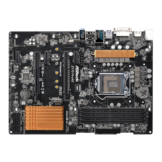
  • Seite 29: Einleitung

    Z170 Pro4S 1 Einleitung Vielen Dank, dass Sie sich für das Z170 Pro4S von ASRock entschieden haben – ein zuverlässiges Motherboard, das konsequent unter der strengen Qualitätskontrolle von ASRock hergestellt wurde. Es liefert ausgezeichnete Leistung mit robustem Design, das ASRocks Streben nach Qualität und Beständigkeit erfüllt.
  • Seite 30: Technische Daten

    Celeron® der 6. Generation (Sockel 1151) • Digipower-Design • 10-Leistungsphasendesign • Unterstützt Intel® Turbo Boost 2.0-Technologie • Unterstützt CPUs mit freiem Multiplikator der Intel® K-Serie • Unterstützt ASRock BCLK-Übertaktung (voller Bereich) ® Chipsatz • Intel Z170 Speicher • Dualkanal-DDR4-Speichertechnologie • 4 x DDR4-DIMM-Steckplätze...
  • Seite 31 ALC892-Audiocodec) * Zur Konfiguration von 7.1-Kanal-HD-Audio müssen Sie ein HD-Frontblenden-Audiomodul nutzen und den Mehrkanalton über den Audiotreiber aktivieren. • Erstklassige Blu-ray-Audiounterstützung • Unterstützt Überspannungsschutz (ASRock Full Spike Protection) • ELNA-Audiokondensatoren • Gigabit LAN 10/100/1000 Mb/s • Giga PHY Intel® I219V • Unterstützt Wake-On-LAN...
  • Seite 32: Anschluss

    • 1 x PCIe-Netzanschluss • 1 x Audioanschluss an Frontblende • 2 x USB 2.0-Stiftleisten (unterstützen 4 USB 2.0-Ports) (unterstützt Schutz gegen elektrostatische Entladung (ASRock Full Spike Protection)) • 1 x USB 3.0-Stiftleiste (unterstützt 2 USB 3.0-Ports) (unterstützt Schutz gegen elektrostatische Entladung (ASRock...
  • Seite 33 • FCC, CE, WHQL zierungen • ErP/EuP ready (ErP/EuP ready-Netzteil erforderlich) * Detaillierte Produktinformationen finden Sie auf unserer Webseite: http://www.asrock.com Bitte beachten Sie, dass mit einer Übertaktung, zu der die Anpassung von BIOS- Einstellungen, die Anwendung der Untied Overclocking Technology oder die Nutzung von Übertaktungswerkzeugen von Drittanbietern zählen, bestimmte Risiken verbunden...
  • Seite 34: Jumpereinstellung

    1.3 Jumpereinstellung Die Abbildung zeigt, wie die Jumper eingestellt werden. Wenn die Jumper-Kappe auf den Kontakten angebracht ist, ist der Jumper „kurzgeschlossen“. Wenn keine Jumper- Kappe auf den Kontakten angebracht ist, ist der Jumper „offen“. Die Abbildung zeigt einen 3-poligen Jumper, dessen Kontakt 1 und Kontakt 2 „kurzgeschlossen“ sind, wenn eine Jumper-Kappe auf diesen 2 Kontakten angebracht ist.
  • Seite 35: Integrierte Stiftleisten Und Anschlüsse

    Z170 Pro4S 1.4 Integrierte Stiftleisten und Anschlüsse Integrierte Stiftleisten und Anschlüsse sind KEINE Jumper. Bringen Sie KEINE Jumper- Kappen an diesen Stiftleisten und Anschlüssen an. Durch Anbringen von Jumper- Kappen an diesen Stiftleisten und Anschlüssen können Sie das Motherboard dauerhaft beschädigen.
  • Seite 36 Betrieb-LED- und Bitte verbinden Sie SPEAKER DUMMY Lautsprecher-Stiftleiste die Betrieb-LED des DUMMY (7-polig, SPK_PLED1) Gehäuses und den (siehe S. 1, Nr. 15) Gehäuselautsprecher mit dieser Stiftleiste. PLED+ PLED+ PLED- Serial-ATA-III- Diese sechs SATA-III- Anschlüsse Anschlüsse unterstützen (SATA3_0: SATA-Datenkabel für siehe S. 1, Nr. 6) interne Speichergeräte mit (SATA3_1: einer Datenübertragungsg...
  • Seite 37 Z170 Pro4S USB 3,0-Stiftleiste Neben sechs USB Vbus Vbus (19-polig, USB3_7_8) 3.0-Ports an der E/ Vbus IntA_PB_SSRX- IntA_PA_SSRX- IntA_PB_SSRX+ (siehe S. 1, Nr. 5) A-Blende befindet sich IntA_PA_SSRX+ IntA_PB_SSTX- eine Stiftleiste an diesem IntA_PA_SSTX- IntA_PB_SSTX+ IntA_PA_SSTX+ Motherboard. Jede USB IntA_PB_D-...
  • Seite 38 Gehäuselüfteran- Bitte verbinden Sie die schlüsse Lüfterkabel mit den (4-polig, CHA_FAN1) Lüfteranschlüssen; der FAN_SPEED_CONTROL CHA_FAN_SPEED (siehe S. 1, Nr. 18) schwarze Draht gehört FAN_VOLTAGE (4-polig, CHA_FAN2) zum Erdungskontakt. (siehe S. 1, Nr. 17) (4-polig, CHA_FAN3) (siehe S. 1, Nr. 26) FAN_VOLTAGE FAN_SPEED CPU-Lüfteranschluss...
  • Seite 39 Z170 Pro4S G e h ä u s e e i n g r i f f - Dieses Motherboard unterstützt Stiftleiste die Gehäuse-offen-Erkennung, Signal (2-polig, CI1) die erkennt, wenn die Gehäusea- (siehe S. 1, Nr. 21) bdeckung entfernt wurde. Diese Funktion setzt ein Gehäuse mit...
  • Seite 40: Contenu De L'emballage

    à modification sans préavis. En cas de modifications du présent document, la version mise à jour sera disponible sur le site Internet ASRock sans notification préalable. Si vous avez besoin d’une assistance technique pour votre carte mère, veuillez visiter notre site Internet pour plus de détails sur le modèle que vous...
  • Seite 41 • Alimentation à 10 phases • Prend en charge la technologie Intel® Turbo Boost 2.0 • Prend en charge les processeurs débloqués de la série K Intel® • Prend en charge l’ o verclocking ASRock BCLK Full-range ® • Intel...
  • Seite 42 • 1 x port HDMI • 6 x ports USB 3.0 (Protection contre les décharges électrostatiques (Protection complète contre les pics ASRock)) • 1 x port RJ-45 LAN avec LED (LED ACT/LIEN et LED VITESSE) • Connecteurs jack audio HD : entrée ligne / haut-parleur avant /...
  • Seite 43 • 1 x socket Ultra M.2, prend en charge les modules M.2 SATA3 6,0 Gb/s et M.2 PCI Express jusqu'à Gen3 x4 (32 Gb/s) * Prend en charge le kit ASRock U.2 Connecteur • 1 x embase pour port COM • 1 x embase d’intrusion châssis...
  • Seite 44 • FCC, CE, WHQL • ErP/EuP Ready (alimentation ErP/EuP ready requise) * pour des informations détaillées de nos produits, veuillez visiter notre site : http://www.asrock.com Il est important de signaler que l’ o vercloking présente certains risques, incluant des modifications du BIOS, l’ a pplication d’une technologie d’ o verclocking déliée et l’utilisation d’...
  • Seite 45 Z170 Pro4S 1.3 Configuration des cavaliers (jumpers) L’illustration ci-dessous vous renseigne sur la configuration des cavaliers (jumpers). Lorsque le capuchon du cavalier est installé sur les broches, le cavalier est « court- circuité ». Si le capuchon du cavalier n’ e st pas installé sur les broches, le cavalier est « ouvert ».
  • Seite 46 1.4 Embases et connecteurs de la carte mère Les embases et connecteurs situés sur la carte NE SONT PAS des cavaliers. Ne placez JAMAIS de capuchons de cavaliers sur ces embases ou connecteurs. Placer un capuchon de cavalier sur ces embases ou connecteurs endommagera irrémédiablement votre carte mère.
  • Seite 47 Z170 Pro4S Prise LED d’alimentation et Veuillez brancher la LED SPEAKER DUMMY haut-parleur d'alimentation du châssis DUMMY (SPK_PLED1 à 7 broches) et le haut-parleur du (voir p.1, No. 15) châssis sur ce connect- sur ce connect- eur. PLED+ PLED+ PLED-...
  • Seite 48 Embases USB 3.0 En plus des six ports Vbus Vbus Vbus IntA_PB_SSRX- (USB3_7_8 19 broches) USB 3.0 sur le panneau IntA_PA_SSRX- IntA_PB_SSRX+ IntA_PA_SSRX+ (voir p.1, No. 5) E/S, cette carte mère IntA_PB_SSTX- IntA_PA_SSTX- IntA_PB_SSTX+ est dotée d’une embase IntA_PA_SSTX+ IntA_PB_D- supplémentaire.
  • Seite 49 Z170 Pro4S Connecteurs du ventilateur Veuillez brancher les du châssis câbles du ventilateur FAN_SPEED_CONTROL (CHA_FAN1 à 4 broches) sur les connecteurs du CHA_FAN_SPEED (voir p.1, No. 18) ventilateur, puis reliez FAN_VOLTAGE (CHA_FAN2 à 4 broches) le fil noir à la broche de (voir p.1, No.
  • Seite 50 Embase pour port série Cette embase COM1 RRXD1 DDTR#1 (COM1 à 9 broches) prend en charge un DDSR#1 CCTS#1 (voir p.1, No. 23) module de port série. RRI#1 RRTS#1 TTXD1 DDCD#1 Embase d’intrusion châssis Cette carte mère prend en (CI1 à 2 broches) charge la fonction de détection Signal (voir p.1, No.
  • Seite 51: Contenuto Della Confezione

    Web per informazioni specifiche relative al modello attualmente in uso. È possibile trovare l'elenco di schede VGA più recenti e di supporto di CPU anche sul sito Web di ASRock. Sito Web di ASRock http:// www.asrock.com.
  • Seite 52 Pentium®/Celeron® (Socket 1151) • Design Digi Power • Potenza a 10 fasi • Supporta la tecnologia Intel® Turbo Boost 2.0 • Supporto di CPU unlocked Intel® K-Series • Supporta gamma completa overclocking BCLK ASRock Chipset ® • Intel Z170 Memoria • Tecnologia memoria DDR4 Dual Channel...
  • Seite 53 • LAN Gigabit 10/100/1000 Mb/s • Giga PHY Intel® I219V • Supporta Wake-On-LAN • Supporto la protezione da fulmini/scariche elettrostatiche (ESD) (protezione completa ASRock dai picchi di corrente) • Supporta Energy Efficient Ethernet 802.3az • Supporta PXE I/O pan- • 1 x porta mouse/tastiera PS/2 nello poste- • 1 x porta DVI-D...
  • Seite 54 • 2 x Collettori USB 2.0 (supporto di 4 porte USB 2.0) (sup- porto protezione da scariche elettrostatiche (ESD) (protezione completa ASRock dai picchi di corrente)) • 1 x Collettore USB 3.0 (supporta 2 porte USB 3.0) (supporto protezione da scariche elettrostatiche (ESD) (protezione com-...
  • Seite 55 * Per installare Windows® 7, è necessario un disco di installazione modificato con i driver xHCI integrati nel file ISO. Fare riferimento a pagina 153 per altre istruzioni dettagliate. * Per il driver aggiornato di Windows® 10, visitare il sito ASRock all’indirizzo:http://www.asrock.com Certificazi- • FCC, CE, WHQL...
  • Seite 56 1.3 Impostazione jumper L'illustrazione mostra in che modo vengono impostati i jumper. Quando il cappuccio del jumper è posizionato sui pin, il jumper è "cortocircuitato". Se sui pin non è posizionato alcun cappuccio del jumper, il jumper è "aperto". L'illustrazione mostra un jumper a 3 pin i cui pin1 e pin2 sono "cortocircuitati"...
  • Seite 57 Z170 Pro4S 1.4 Header e connettori sulla scheda Gli header e i connettori sulla scheda NON sono jumper. NON posizionare cappucci del jumper su questi header e connettori. Il posizionamento di cappucci del jumper su header e connettori provocherà danni permanenti alla scheda madre.
  • Seite 58 Connettore LED Collegare i LED alimen- SPEAKER DUMMY alimentazione e tazione e l’altoparlante a DUMMY altoparlante questo connettore. (SPK_PLED1 7 pin) (vedere pag. 1, n. 15) PLED+ PLED+ PLED- Connettori Serial ATA3 Questi sei connettori (SATA3_0: SATA3 supportano cavi vedere pag. 1, n. 6) dati SATA per dispositivi (SATA3_1: di archiviazione interna,...
  • Seite 59 Z170 Pro4S Header USB 3.0 Oltre alle sei porte USB Vbus Vbus Vbus IntA_PB_SSRX- (USB3_7_8 19 pin) 3.0 del pannello I/O, IntA_PA_SSRX- IntA_PB_SSRX+ IntA_PA_SSRX+ (vedere pag. 1, n. 5) questa scheda madre è IntA_PB_SSTX- IntA_PA_SSTX- IntA_PB_SSTX+ dotata di un collettore.
  • Seite 60 Connettori ventola telaio Collegare i cavi della (CHA_FAN1 a 4 pin) ventola ai connettori FAN_SPEED_CONTROL (vedere pag. 1, n. 18) della ventola e far CHA_FAN_SPEED (CHA_FAN2 a 4 pin) corrispondere il filo nero FAN_VOLTAGE (vedere pag. 1, n. 17) al pin di terra. (CHA_FAN3 a 4 pin) (vedere pag.
  • Seite 61 Z170 Pro4S Header di intrusione nello Questa scheda madre supporta chassis la funzionalità di rilevamento Signal (CI1 a 2 pin) CASE OPEN che rileva se (vedere pag. 1, n. 21) il coperchio dello chassis è stato rimosso. Questa funzi- one richiede uno chassis con caratteristiche di rilevamento di intrusione nello chassis.
  • Seite 62: Contenido Del Paquete

    Podrá encontrar las últimas tarjetas VGA, así como la lista de compatibilidad de la CPU, en el sitio web de ASRock. Sitio web de ASRock http://www.asrock.com.
  • Seite 63 2800(OC)/2400(OC)/2133 no ECC. * Para obtener más información, consulte la lista de memorias compatibles en el sitio web de ASRock. (http://www.asrock.com/) • Capacidad máxima de la memoria del sistema: 64GB • Admite Perfil de memoria extremo de Intel® (XMP) 2.0 Ranura de • 2 x Ranuras PCI Express 3.0 x16 (PCIE2:modo x16;...
  • Seite 64 I/O • 1 puerto HDMI • 6 puertos USB 3.0 (compatible con protección contra electricidad estática (protección ASRock Full Spike)) • 1 puerto LAN RJ-45 con LED (ACT/LINK LED y SPEED LED) • Conector de audio HD: Entrada de línea / Altavoz frontal / Micrófono...
  • Seite 65 SATA3_1 se deshabilitará. • 1 x Zócalo Ultra M.2, que admite el módulo SATA3 6,0 Gb/s M.2 y el módulo PCI Express M.2 hasta Gen3 x4 (32 Gb/s) * Admiteel Kit U.2 de ASRock Conector • 1 Cabezal de puerto COM • 1 cabezal de intrusión de chasis...
  • Seite 66 • Compatible con ErP/EuP (requiere toma de alimentación compatible con ErP/EuP) * Para obtener más información acerca del producto, visite nuestro sitio web: http://www.asrock.com Tenga en cuenta que existen ciertos riesgos relacionados con el overclocking (sobreacel- eración), incluyendo el ajuste de la configuración del BIOS, aplicando la Tecnología overcloking no vinculada o utilizando las herramientas de overclocking de tercera parte.
  • Seite 67 Z170 Pro4S 1.3 Instalación de los puentes La instalación muestra cómo deben instalarse los puentes. Cuando la tapa de puente se coloca en los pines, el puente queda “Corto”. Si no coloca la tapa de puente en los pines, el puente queda “Abierto”. La ilustración muestra un puente de 3 pines cuyo pin 1 y pin 2 son “Cortos”...
  • Seite 68 1.4 Conectores y cabezales incorporados Los cabezales y conectores incorporados NO son puentes. NO coloque tapas de puente so- bre estos cabezales y conectores. Si coloca tapas de puente sobre los cabezales y conectores dañará de forma permanente la placa base. Cabezal del panel del Conecte el interruptor PLED+...
  • Seite 69 Z170 Pro4S LED de alimentación y Conecte el LED de SPEAKER DUMMY base de conexiones para la alimentación del chasis y DUMMY altavoz el altavoz del chasis a esta (SPK_PLED1 de 7 base de conexiones. contactos) PLED+ (consulte la pág.1, N.º 15)
  • Seite 70 Cabezal USB 3.0 Además de seis puertos Vbus Vbus Vbus IntA_PB_SSRX- (USB3_7_8 de 19 USB 3.0 en el panel I/O, IntA_PA_SSRX- IntA_PB_SSRX+ IntA_PA_SSRX+ contactos) esta placa base contiene IntA_PB_SSTX- IntA_PA_SSTX- IntA_PB_SSTX+ (consulte la pág.1, N.º 5) un cabezal. Cada cabezal IntA_PA_SSTX+ IntA_PB_D- USB 3.0 admite dos...
  • Seite 71 Z170 Pro4S Conectores para el venti- Conecte los cables lador del chasis del ventilador a los FAN_SPEED_CONTROL (CHA_FAN1 de 4 pines) conectores del ventilador CHA_FAN_SPEED FAN_VOLTAGE (consulte la pág.1, N.º 18) y haga coincidir el cable (CHA_FAN2 de 4 pines) negro con el pin de (consulte la pág.1, N.º...
  • Seite 72 Cabezal de intrusión de Esta placa base es compatible chasis con la función de detección Signal (CI1 de 2 pines) de CUBIERTA ABIERTA que (consulte la pág.1, N.º 21) detecta si se ha retirado la cu- bierta del chasis. Esta función requiere un chasis diseñado para la detección de intrusión del chasis.
  • Seite 73: Комплект Поставки

    • Материнская плата ASRock Z170 Pro4S (форм-фактор ATX) • Краткое руководство по установке ASRock Z170 Pro4S • Компакт-диск с ПО для платы ASRock Z170 Pro4S • 2 х кабеля передачи данных Serial ATA (SATA) (приобретаются отдельно) • 1 х экран панели с портами ввода-вывода...
  • Seite 74 (Socket 1151) • Digi Power design • Система питания 10 • Поддержка технологии Intel® Turbo Boost 2.0 • Поддержка процессоров Intel® серии K с разблокированным множителем • Поддержка полного разгона процессора ASRock BCLK • Intel ® Z170 Чипсет Память...
  • Seite 75 HD Audio используйте переднюю аудиопанель HD и активируйте функцию многоканального звука в аудиодрайвере. • Поддержка Premium Blu-ray Audio • Защита от перенапряжения (ASRock Full Spike Protection) • Конденсаторы для аудиосистем ELNA • Gigabit LAN 10/100/1000 Мб/с • Giga PHY Intel® I219V • Поддержка...
  • Seite 76 • 1 x Ultra M.2 Socket, поддержка модуля M.2 SATA3 со скоростью обмена данными 6,0 ГБ/с и модуля M.2 PCI Express до версии Gen3 x4 (32 ГБ/с) * Поддержка комплекта ASRock U.2 Разъемы • 1 x колодка СОМ-порта • 1 x Колодка для датчика вскрытия корпуса...
  • Seite 77 измененный установочный диск с драйверами xHCI, упакованными в файл ISO. Более подробные инструкции представлены на стр. 153. * Подробные сведения об обновлении драйвера Win- dows® 10 представлены на веб-сайте ASRock: http:// www.asrock.com Сертификация • FCC, CE, WHQL • Совместимость с ErP/EuP (необходим блок питания, соответствующий...
  • Seite 78 1.3 Установка перемычек Установка перемычек показана на рисунке. При установке колпачковой перемычки на контакты перемычка «замкнута». Если колпачковая перемычка на контакты не установлена, перемычка «разомкнута». На рисунке показана 3-контактная перемычка с замкнутыми контактами 1 и 2 при установке на них колпачковой...
  • Seite 79 Z170 Pro4S 1.4 Колодки и разъемы, расположенные на материнской плате Расположенные на материнской плате колодки и разъемы перемычками НЕ являются. НЕ устанавливайте на эти колодки и разъемы колпачковые перемычки. Установка колпачковых перемычек на эти колодки и разъемы может вызвать неустранимое повреждение материнской платы.
  • Seite 80 Колодка светодиодного Предназначена SPEAKER индикатора питания и для подключения DUMMY DUMMY динамика корпуса светодиодного (7-контактная, SPK_ индикатора питания и PLED1) динамика корпуса. (См. стр. 1, № 15) PLED+ PLED+ PLED- Разъемы Serial ATA3 Эти шесть (SATA3_0: разъемов SATA3 См. стр. 1, № 6) предназначены...
  • Seite 81 Z170 Pro4S Колодка USB 3.0 Кроме шести портов Vbus Vbus Vbus IntA_PB_SSRX- (19-контактная,USB3_7_8) USB 3.0 на панели IntA_PA_SSRX- IntA_PB_SSRX+ IntA_PA_SSRX+ (См. стр. 1, № 5) ввода-вывода на IntA_PB_SSTX- IntA_PA_SSTX- IntA_PB_SSTX+ системной плате IntA_PA_SSTX+ IntA_PB_D- также имеется одна IntA_PA_D- IntA_PB_D+ IntA_PA_D+ Dummy колодка.
  • Seite 82 Разъемы вентиляторов Предназначены для корпуса подключения кабелей FAN_SPEED_CONTROL (4-контактный, CHA_FAN1) разъемов вентиляторов CHA_FAN_SPEED (См. стр. 1, № 18) и подключения черного FAN_VOLTAGE (4-контактный, CHA_FAN2) провода к заземлению. (См. стр. 1, № 17) (4-контактный, CHA_FAN3) FAN_VOLTAGE FAN_SPEED (См. стр. 1, № 26) Разъем...
  • Seite 83 Z170 Pro4S Колодка последовательного Колодка COM1 RRXD1 DDTR#1 порта DDSR#1 поддерживает CCTS#1 (9-контактная, COM1) подключение модуля (См. стр. 1, № 23) последовательного RRI#1 RRTS#1 порта. TTXD1 DDCD#1 Колодка для датчика Эта материнская плата вскрытия корпуса поддерживает технологию Signal (2-контактная, CI1) определения...
  • Seite 84: Conteúdo Da Embalagem

    1 Introdução Obrigado por adquirir a placa mãe ASRock Z170 Pro4S, uma confiável placa mãe ASRock produzida sob rigoroso controle de qualidade consistente. Esta placa principal oferece um excelente desempenho com um design robusto em conformidade com o compromisso da ASRock em fabricar produtos de qualidade e resistentes.
  • Seite 85: Especificações

    Pentium®/Celeron® (Soquete 1151) • Design Digi Power • Design com 10 fases de alimentação • Suporta a tecnologia Intel® Turbo Boost 2.0 • Suporta CPU desbloqueado da série K da Intel® • Suporta Overclocking total ASRock BCLK ® Chipset • Intel Z170 Memória...
  • Seite 86 • LAN Gigabit a 10/100/1000 Mb/s • Giga PHY Intel® I219V • Suporta Wake-On-LAN • Suporta Proteção contra Relâmpago/EDS (Proteção Total Contra Picos ASRock) • Suporta Energy Efficient Ethernet 802.3az • Suporta PXE E/S do painel • 1 x Porta PS/2 para mouse/teclado posterior • 1 x Porta DVI-D...
  • Seite 87 • 1 conector de áudio do painel frontal • 2 x Plataformas USB 2.0 (Suporta 4 portas USB 2.0) (Suporta Proteção ESD (Proteção Total Contra Picos ASRock)) • 1 x Plataforma USB 3.0 (Suporta 2 portas USB 3.0) (Suporta Proteção ESD (Proteção Total Contra Picos ASRock)) Funções da...
  • Seite 88 • Preparada para ErP/EuP (é necessária uma fonte de alimen- tação preparada para ErP/EuP) * Para obter informações detalhadas sobre o produto, por favor, visite o nosso site: http://www.asrock.com Por favor, observe que existe um certo risco envolvendo overclocking, incluindo o ajuste das definições na BIOS, a aplicação de tecnologia Untied Overclocking ou a utilização...
  • Seite 89 Z170 Pro4S 1.3 Configuração dos jumpers A imagem abaixo mostra como os jumpers são configurados. Quando a tampa do jumper é colocada nos pinos, o jumper é "Curto". Se não for colocada uma tampa de jumper nos pinos, o jumper é "Aberto". A imagem mostra um jumper de 3 pinos cujos pino1 e pino2 estão "Curtos"...
  • Seite 90 1.4 Suportes e conectores onboard Os conectores e suportes onboard NÃO são jumpers. NÃO coloque tampas de jumpers sobre estes terminais e conectores Colocar tampas de jumpers sobre os terminais e conec- tores irá causar danos permanentes à placa-mãe. Suporte do painel de Ligue o botão de PLED+ PLED-...
  • Seite 91 Z170 Pro4S LED de alimentação e Conecte o LED de SPEAKER DUMMY Cabeçote de Autofalante alimentação do chassi e o DUMMY (SPK_PLED1 7 pinos) autofalante do chassi a este (ver p.1, N.º 15) cabeçote. PLED+ PLED+ PLED- Conectores série ATA3...
  • Seite 92 Suporte USB 3.0 Além de seis portas USB Vbus Vbus Vbus IntA_PB_SSRX- (USB3_7_8 19 pinos) 3.0 no painel I/O, existe IntA_PA_SSRX- IntA_PB_SSRX+ IntA_PA_SSRX+ (ver p.1, N.º 5) uma plataforma nesta IntA_PB_SSTX- IntA_PA_SSTX- IntA_PB_SSTX+ placa-mãe. Cada suporte IntA_PA_SSTX+ IntA_PB_D- USB 3.0 pode suportar IntA_PA_D- IntA_PB_D+ IntA_PA_D+...
  • Seite 93 Z170 Pro4S Conectores da Ventoinha Por favor, conecte os do Chassi cabos do ventilador aos (CHA_FAN1 de 4 pinos) conectores do ventilador e FAN_SPEED_CONTROL CHA_FAN_SPEED (ver p.1, N.º 18) corresponda o fio preto no FAN_VOLTAGE (CHA_FAN2 4 pinos) pino terra.
  • Seite 94 Suporte de intrusão do Esta placa-mãe suporta a função chassi de detecção de ABERTURA da Signal (CI1 de 2 pinos) CAIXA que detecta se a tampa do (ver p.1, N.º 21) chassi foi removida. Esta função requer um chassi com design de detecção de intrusão.
  • Seite 95: Ambalaj İçeriği

    ASRock'ın web sitesinde yer alacaktır.. Bu anakart ile ilgili olarak teknik destek almak istiyorsanız, lütfen kullandığınız model hakkında özel bilgiler için web sitemizi ziyaret edin. En güncel VGA kartları ve CPU destek listelerini de ASRock'ın web sitesinden bulabilirsiniz. ASRock web sitesi http://www.asrock.com.
  • Seite 96 • 4 x DDR4 DIMM Yuvası • DDR4 3200+(OC)*/2933(OC)/2800(OC)/2400(OC)/2133 ECC olmayan, arabelleksiz bellek destekler * Ayrıntılı bilgi için ASRock'ın web sitesindeki Bellek Desteği Listesine bakın. (http://www.asrock.com/) • Maksimum sistem belleği kapasitesi: 64GB • Intel® Üstün Bellek Profili (XMP) 2.0 destekler Genişletme...
  • Seite 97 * 7.1 CH HD Ses konfigürasyonu için bir HD ön panel ses modülü kullanılmalı ve çok kanallı ses özelliği ses sürücüsüsü ile etkinleştirilmelidir. • Üstün Blu-ray Ses desteği • Dalgalanma Koruması Destekler (ASRock Tam Ani Gerilim Koruması) • ELNA Ses Kapakları • Gigabit LAN 10/100/1000 Mb/s • Giga PHY Intel®...
  • Seite 98 • 1 x Ön Panel Ses Bağlayıcısı • 2 x USB 2.0 Bağlantısı (4 USB 2.0 bağlantı noktası destek- ler) (ESD Koruması Destekler (ASRock Tam Ani Gerilim Koruması)) • 1 x USB 3.0 Bağlantısı (2 USB 3.0 bağlantı noktası destek- ler) (ESD Koruması...
  • Seite 99 • ErP/EuP için hazır (ErP/EuP için hazır güç beslemesi gereklidir) * Detaylı ürün bilgisi için, lütfen web sitemizi ziyaret edin: http://www.asrock.com Lütfen, BIOS ayarlarını düzenleme, Bağımsız Hız Aşırtma Teknolojinin uygulanması ya da üçüncü kişilerin hız aşırtma araçlarının kullanılması da dahil olmak üzere tüm hız aşırtma işlemlerinin belirli bir risk taşıdığını...
  • Seite 100 1.3 Bağlantı Teli Kurulumu Çizim, bağlantı tellerinin kurulumunu göstermektedir. Tel kapağı, pimlerin üzerine yerleştirildiğinde, tel "Kısa" olur. Pimlerin üzerinde tel kapağı bulunmadığında, tel "Açık" olur. Çizim, pin1 ve pin2 alanları "Kısa" olan ve bu iki pim üzerinde bir bağlantı teli kapağı bulunan 3-pin bağlantı telini göstermektedir. CMOS'u Temizle Bağlantı...
  • Seite 101 Z170 Pro4S 1.4 Ekli Bağlantılar ve Bağlayıcılar Ekli bağlantılar ve bağlayıcılar bağlantı teli değildir. Bağlantı teli kapaklarını bu bağlantı ve bağlayıcılar üzerine yerleştirmeyin. Bağlantı teli kapaklarının bağlantılar ile bağlayıcılar üzerine yerleştirilmesi, anakarta kalıcı hasar verebilir. Sistem Paneli Bağlantısı Güç anahtarını bağlayın,...
  • Seite 102 Güç LED’i ve Hoparlör Lütfen kasa güç LED’ini SPEAKER Bağlantısı DUMMY ve kasa hoparlörünü bu DUMMY (7 pimli SPK_PLED1) bağlantıya takın. (bkz. sf.1, No. 15) PLED+ PLED+ PLED- Seri ATA3 Bağlayıcıları Bu altı SATA3 bağlayıcısı, (SATA3_0: veri aktarım hızı 6,0 Gb/ bkz.
  • Seite 103 Z170 Pro4S USB 3.0 Bağlantı Bu anakart üzerinde, G/Ç Vbus Vbus Vbus IntA_PB_SSRX- (19-pin USB3_7_8) paneli üzerindeki dört USB IntA_PA_SSRX- IntA_PB_SSRX+ IntA_PA_SSRX+ (bkz. sf.1, No. 5) 3.0 bağlantı noktasının IntA_PB_SSTX- IntA_PA_SSTX- IntA_PB_SSTX+ yanı sıra bir adet bağlantı IntA_PA_SSTX+ IntA_PB_D- bulunmaktadır. Her...
  • Seite 104 Kasa Fanı Bağlayıcıları Lütfen fan kablolarını (4-pin CHA_FAN1) fan bağlayıcılarına takın FAN_SPEED_CONTROL (bkz sf.1, No. 18) ve siyah teli topraklama CHA_FAN_SPEED (4-pin CHA_FAN2) FAN_VOLTAGE pinine bağlayın. (bkz sf.1, No. 17) (4-pin CHA_FAN3) (bkz sf.1, No. 26) FAN_VOLTAGE FAN_SPEED CPU Fan Bağlayıcısı Bu anakart, 4-Pin CPU (4-pin CPU_FAN1) fan (Sessiz Fan) bağlayıcısı...
  • Seite 105 Z170 Pro4S Kasa Yetkisiz Erişim Bu anakartın kasa kapağının açılıp Bağlantısı açılmadığını tespit eden bir KASA Signal (2-pin CI1) AÇIK özelliği bulunmaktadır. Bu (bkz. sf.1, No. 21) özelliğin kullanılabilmesi için kasa yetkisiz erişim tasarımına sahip bir kasa kullanılmalıdır. TPM bağlantısı...
  • Seite 106 마더보드 규격과 BIOS 소프트웨어를 업데이트할 수도 있기 때문에 , 이 문서의 내용은 예고 없이 변경될 수 있습니다 . 이 설명서가 변경될 경우 , 업데이트된 버 전은 ASRock 의 웹사이트에서 추가 통지 없이 제공됩니다 . 이 마더보드와 관련 하여 기술적 지원이 필요한 경우 , 당사의 웹사이트를 방문하여 사용 중인 모델...
  • Seite 107 • DDR4 DIMM 슬롯 4 개 • DDR4 3200+(OC)*/2933(OC)/2800(OC)/2400(OC)/2133 비 -ECC, 비버퍼링 메모리 지원 * 추가 정보를 원하시면 ASRock 웹사이트에 있는 메모리 지원 목록을 참조하십시오 . (http://www.asrock.com/) • 시스템 메모리 최대 용량 : 64GB • Intel® Extreme Memory Profile (XMP)2.0 지원...
  • Seite 108 후면 패널 • DVI-D 포트 1 개 • HDMI 포트 1 개 • USB 3.0 포트 6 개 (ESD 보호 지원 (ASRock 풀 스파이크 보 호 )) • LED 장착 RJ-45 LAN 포트 1 개 (ACT/LINK LED 및 SPEED LED) •...
  • Seite 109 SATA3_1 이 비활성화됩니다 . • 울트라 M.2 소켓 1 개 , M.2 SATA3 6.0 Gb/s 모듈 및 Gen3 M.2 PCI Express 모듈 4 개 (32 Gb/s) 지원 * ASRock U.2 키트 지원 • COM 포트 헤더 1 개 커넥터 • 섀시 침입 헤더 1 개...
  • Seite 110 인증 • ErP/EuP 사용 가능 (ErP/EuP 사용 가능 전원공급장치 필요 ) * 자세한 제품 정보에 대해서는 당사 웹사이트를 참조하십시오 : http://www.asrock.com BIOS 설정을 조정하거나 Untied Overclocking Technology 를 적용하거나 타업체 의 오버클로킹 도구를 사용하는 것을 포함하는 오버클로킹에는 어느 정도의 위...
  • Seite 111 Z170 Pro4S 1.3 점퍼 설정 그림은 점퍼를 어떻게 설정하는지 보여줍니다 . 점퍼 캡을 핀에 씌우면 점퍼가 “단락” 됩니다 . 점퍼 캡을 핀에 씌우지 않으면 점퍼가 “단선”됩니다 . 그림은 3 핀 점퍼를 보여주며 핀 1 과 핀 2 는 점퍼 캡을 씌울 때 “단락”됩니다 .
  • Seite 112 1.4 온보드 헤더 및 커넥터 온보드 헤더와 커넥터는 점퍼가 아닙니다 . 점퍼 캡을 온보드 헤더와 커넥터에 씌우지 마십시오 . 점퍼 캡을 온보드 헤더와 커넥터에 씌우면 마더보드가 영구 적으로 손상됩니다 . 시스템 패널 헤더 섀시의 전원 스위 PLED+ PLED- (9 핀 PANEL1) 치...
  • Seite 113 Z170 Pro4S SPEAKER 전원 LED 및 스피커 헤더 섀시 전원 LED 와 DUMMY (7 핀 SPK_PLED1) 섀시 스피커를 이 DUMMY (1 페이지 , 15 번 항목 참조 ) 헤더에 연결하십 시오 . PLED+ PLED+ PLED- 시리얼 ATA3 커넥터 이들 6 개의 SATA3 (SATA3_0: 커넥터는...
  • Seite 114 USB 3.0 헤더 I/O 패널에 USB Vbus Vbus Vbus IntA_PB_SSRX- (19 핀 USB3_7_8) 3.0 포트 여섯 개 IntA_PA_SSRX- IntA_PB_SSRX+ IntA_PA_SSRX+ (1 페이지 , 5 번 항목 참조 ) 가 탑재되어 있을 IntA_PB_SSTX- IntA_PA_SSTX- IntA_PB_SSTX+ 뿐 아니라 마더보 IntA_PA_SSTX+ IntA_PB_D- 드에 헤더 한 개 IntA_PA_D- IntA_PB_D+ IntA_PA_D+...
  • Seite 115 Z170 Pro4S 섀시 팬 커넥터 팬 케이블을 팬 (4 핀 CHA_FAN1) 커넥터에 연결하 FAN_SPEED_CONTROL (1 페이지 , 18 번 항목 참조 ) 고 검은색 와이어 CHA_FAN_SPEED (4 핀 CHA_FAN2) FAN_VOLTAGE 를 접지핀에 연결 (1 페이지 , 17 번 항목 참조 ) 하십시오...
  • Seite 116 이 COM1 헤더는 시리얼 포트 헤더 RRXD1 DDTR#1 (9 핀 COM1) 시리얼 포트 모듈 DDSR#1 CCTS#1 (1 페이지 , 23 번 항목 참조 ) 을 지원합니다 . RRI#1 RRTS#1 TTXD1 DDCD#1 섀시 침입 헤더 이 마더보드는 섀시 커 (2 핀 CI1) 버가...
  • Seite 117 アルの内容は予告なしに変更するこ とがあります。 このマニュアルの内容に変更 があった場合には、 更新されたバージョンは、 予告なく アスロックのウェブサイ トか ら入手できるようになります。 このマザーボードに関する技術的なサポートが必要 な場合には、 ご使用のモデルについての詳細情報を、 当社のウェブサイ トで参照く ださい。 ASRock のウェブサイ トでは、 最新の VGA カードおよび CPU サポート一覧 もご覧になれます。 ASRock ウェブサイ ト http://www.asrock.com. 1.1 パッケージの内容 • ASRock Z170 Pro4S マザーボード (ATX フォームファクタ) • ASRock Z170 Pro4S クイックインストールガイ ド...
  • Seite 118 • デュアルチャンネル DDR4 メモリテク ノロジー メモリ • 4 x DDR4 DIMM スロッ ト • DDR4 3200+(OC)*/2933(OC)/2800(OC)/ 2400(OC)/2133 ノン ECC、 アンバッファードメモリに対応 * 詳細については、 ASRock ウェブサイ トのメモリーサポート 一覧を参照してく ださい。 (http://www.asrock.com/) • システムメモリの最大容量 : 64GB • Intel® エクストリームメモリプロファイル (XMP) 2.0 に対 応 • 2 x PCI Express 3.0 x16 スロッ ト (PCIE2: x16 モード、...
  • Seite 119 • 1 x PS/2 マウス / キーボードポート リアパネル I/O • 1 x DVI-D ポート • 1 x HDMI ポート • 6 x USB 3.0 ポート (静電気放電 (ESD) 保護に対応 (ASRock 完全スパイク保護) ) • LED 付き 1 x RJ-45 LAN ポート (ACT/LINK LED と SPEED LED)...
  • Seite 120 • 1 x 前面パネルオーディオコネクタ • 2 x USB 2.0 ヘッダー (4 個の USB 2.0 ポートに対応) ( 静 電気放電 (ESD) 保護に対応 (ASRock 完全スパイク保護) ) • 1 x USB 3.0 ヘッダー (2 個の USB 3.0 ポートに対応) ( 静 電気放電 (ESD) 保護に対応 (ASRock 完全スパイク保護) )...
  • Seite 121 64-bit * Windows® 7 OS をインストールするために、 xHCI ドライバ が ISO ファイルに含まれる変更されたインストールディス クが必要です。 詳しい説明については 153 ページを参照し てく ださい。 * 更新された Windows® 10 ドライバについては、 ASRock の ウェブサイ トで詳細をご確認く ださい : http://www.asrock. • FCC、 CE、 WHQL 認証 • ErP/EuP Ready ( ErP/EuP 対応電源供給装置が必要です)...
  • Seite 122 1.3 ジャンパー設定 このイラストは、 ジャンパーの設定方法を示しています。 ジャンパーキャップがピ ンに被さっていると、 ジャンパーは 「ショート」 です。 ジャンパーキャップがピンに被 さっていない場合には、 ジャンパーは 「オープン」 です。 この図は 3ピンのジャンパー を表し、 ジャンパーキャップがピン 1 とピン 2 に被さっているとき、 これらのピンは 「ショート」 です。 CMOS ク リアジャンパー (CLRMOS1) デフォルト CMOS のクリア (p.1、 No. 25 参照) CLRCMOS1 を使って CMOS 内のデータをクリアできます。 ク リアして、 デフォル ト設定にシステムパラメーターをリセッ...
  • Seite 123 Z170 Pro4S 1.4 オンボードのヘッダーとコネクター オンボードヘッダーとコネクターはジャンパーではありません。 これらヘッダーと コネクターにはジャンパーキャップを被せないでく ださい。 ヘッダーおよびコネク ターにジャンパーキャップを被せると、 マザーボードに永久損傷が起こるこ とがあ ります。 システムパネルヘッダー 電源スイッチを接続 PLED+ PLED- (9 ピンパネル 1) し、 スイッチをリセッ ト PWRBTN# (p.1、 No. 13 参照) し、 下記のピン割り当 てに従って、 シャーシ のシステムステータス RESET# HDLED- 表示ランプをこのヘッ HDLED+ ダーにセッ トします。 ケーブルを接続する...
  • Seite 124 電源 LED とスピーカーヘ SPEAKER シャーシ電源 LED と DUMMY ッダー シャーシスピーカーを DUMMY (7 ピン SPK_PLED1) このヘッダーに接続し (p.1、 No. 15 参照) てく ださい。 PLED+ PLED+ PLED- シリアル ATA3 コネクター これら 6 つの SATA3 コネクターは、 最高 6.0 (SATA3_0: p.1、 No. 6 参照) Gb/ 秒のデータ転送 速度で内部ストレー...
  • Seite 125 Z170 Pro4S USB 3.0 ヘッダー I/O パネルの 6 つの Vbus Vbus Vbus IntA_PB_SSRX- (19 ピン USB3_7_8) USB 3.0 ポートに加え IntA_PA_SSRX- IntA_PB_SSRX+ IntA_PA_SSRX+ (p.1、 No. 5 参照) て、 このマザーボード IntA_PB_SSTX- IntA_PA_SSTX- IntA_PB_SSTX+ には 1 つのヘッダー IntA_PA_SSTX+ IntA_PB_D- が装備されています。 IntA_PA_D- IntA_PB_D+ IntA_PA_D+ Dummy 各...
  • Seite 126 シャーシファンコネクタ ファンケーブルはファ (4 ピン CHA_FAN1) ンコネクターに接続 FAN_SPEED_CONTROL (p.1、 No. 18 参照) し、 黒線とアースピン CHA_FAN_SPEED (4 ピン CHA_FAN2) FAN_VOLTAGE を合わせてく ださい。 (p.1、 No. 17 参照) (4 ピン CHA_FAN3) (p.1、 No. 26 参照) FAN_VOLTAGE FAN_SPEED CPU ファンコネクタ このマザーボードは 4 (4 ピン CPU_FAN1) ピン...
  • Seite 127 Z170 Pro4S ケースイントリュージョン このマザーボードはシャーシ ヘッダー カバーが開けられたこ とを Signal (2 ピン CI1) 検知する、 ケース開閉検知機 (p.1、 No. 21 参照) 能をサポートします。 この機 能には、 シャーシイントルー ジョン検知設計されたシャー シが必要です。 TPM ヘッダー このコネクターはトラステッ (17 ピン TPMS1) ドプラッ トフォームモジュール (p.1、 No. 22 参照) (TPM) システムをサポート し、 鍵、 デジタル証明書、 パス...
  • Seite 128 恕不另行通知。如果本文档有任何修改,则更新的版本将发布在华擎网站上, 我们不会另外进行通知。如果您需要与此主板相关的技术支持,请访问我们的 网站以具体了解所用型号的信息。您也可以在华擎网站上找到最新 VGA 卡和 CPU 支持列表。华擎网站 http://www.asrock.com。 1.1 包装清单 • 华擎 Z170 Pro4S 主板(ATX 规格尺寸) • 华擎 Z170 Pro4S 快速安装指南 • 华擎 Z170 Pro4S 支持光盘 • 2 x 串行 ATA (SATA) 数据线(选购) • 1 x I/O 面板 • 1 x 螺丝(供 M.2 插座使用)...
  • Seite 129 内存 • 4 x DDR4 DIMM 槽 • 支持 DDR4 3200+(OC)*/2933(OC)/2800(OC)/2400 (OC)/2133 非 ECC,非缓冲内存 * 请参阅 ASRock 网站上的 Memory Support List(内存支持列 表)了解详情。 (http://www.asrock.com/) • 支持系统内存容量: 64GB • 支持 Intel® Extreme Memory Profile (XMP) 2.0 • 2 x PCI Express 3.0 x16 槽 (PCIE2:x16 模式;PCIE4:x4 模式 ) 扩充槽...
  • Seite 130 • 双图形输出 : 通过独立显示控制器支持 DVI-D 和 HDMI 端 口 • 支持 HDMI,最大分辨率可达 4K x 2K (4096x2304) @ 24Hz • 支持 DVI-D,60Hz 时最大分辨率达 1920x1200 • 通过 HDMI 端口(需要兼容的 HDMI 显示器)支持 Auto Lip Sync、Deep Color (12bpc), xvYCC 和 HBR(高位速率音 频) • 支持“加速媒体编解码器”: HEVC, VP8, VP9 •...
  • Seite 131 Z170 Pro4S • 6 x SATA3 6.0 Gb/s 接口 (Intel® Z170), 支持 RAID (RAID 0、 存储 RAID 1、RAID 5、RAID 10、Intel Rapid Storage Technology 14 和 Intel Smart Response Technology)、NCQ、AHCI 和热 插拔 • 2 x SATA Express 10 Gb/s 接口 * * 即将支持...
  • Seite 132 • Microsoft® Windows® 10 64-bit / 8.1 64-bit / 7 32-bit / 7 64-bit 操作系统 * 要安装 Windows® 7 OS,需要 xHCI 驱动程序已封闭到 ISO 文件的经修改的安装盘。请参考第 153 页了解详情。 * 有关已更新的 Windows® 10 驱动程序,请访问 ASRock 网站 了解详情 : http://www.asrock.com • FCC、CE、WHQL 认证 • ErP/EuP 支持(需要支持 ErP/EuP 的电源)...
  • Seite 133 Z170 Pro4S 1.3 跳线设置 此图显示如何设置跳线。 将跳线帽装到这些针脚上时,跳线 “短接”。 如果 这些针脚上没有装跳线帽,跳线 “开路”。 此图显示 3 针跳线,当跳线帽装在 针脚 1 和针脚 2 上,它们“短接”。 清除 CMOS 跳线 (CLRMOS1) 清除 CMOS 默认 (见第 1 页,第 25 个) CLRMOS1 允许您清除 CMOS 中的数据。要清除和重置系统参数到默认设 置,请关闭计算机,从电源上拔下电源线插头。等候 15 秒后,使用跳线帽将 CLRMOS1 上的针脚 2 和针脚 3 短接 5 秒。但是,请勿在更新 BIOS 后立即清...
  • Seite 134 1.4 板载接脚和接口 板载接脚和接口不是跳线。 不要将跳线帽装到这些接脚和接口上。 将跳线帽装 到这些接脚和接口上将会对主板造成永久性损坏。 系统面板接脚 按照下面的针脚分 PLED+ PLED- (9 针 PANEL1) 配,将机箱上的电源 PWRBTN# (见第 1 页, 第 13 个) 开关、重置开关和系 统状态指示灯连接到 RESET# 此接脚。在连接线缆 HDLED- 前请记下正负针脚。 HDLED+ PWRBTN(电源开关): 连接到机箱前面板上的电源开关。您可以配置使用电源开关关闭系统的方式。 RESET(重置开关): 连接到机箱前面板上的重置开关。如果计算机死机,无法执行正常重新启动, 按重置开关重新启动计算机。 PLED(系统电源 LED): 连接到机箱前面板上的电源状态指示灯。系统操作操作时,此 LED 亮起。系统 处在 S1/S3 睡眠状态时,此 LED 闪烁。系统处在 S4 睡眠状态或关机 (S5) 时, 此...
  • Seite 135 Z170 Pro4S 电源 LED 和扬声器接脚 请将机箱电源 LED 和 SPEAKER DUMMY (7 针 SPK_PLED1) 机箱扬声器连接到此 DUMMY (见第 1 页,第 15 个) 接脚。 PLED+ PLED+ PLED- 串行 ATA3 接口 这六个 SATA3 接口 (SATA3_0: 支持最高 6.0 Gb/s 数 见第 1 页, 第 6 个)...
  • Seite 136 USB 3.0 接脚 除 I/O 面板上的六个 Vbus Vbus Vbus IntA_PB_SSRX- (19 针 USB3_7_8) USB 3.0 端口外,此主 IntA_PA_SSRX- IntA_PB_SSRX+ IntA_PA_SSRX+ (见第 1 页,第 5 个) 板上还有一个接脚。 IntA_PB_SSTX- IntA_PA_SSTX- IntA_PB_SSTX+ 每个 USB 3.0 接脚可 IntA_PA_SSTX+ IntA_PB_D- 以支持两个端口。 IntA_PA_D- IntA_PB_D+ IntA_PA_D+ Dummy 前面板音频接脚 此接脚用于将音频设...
  • Seite 137 Z170 Pro4S 机箱风扇接口 请将风扇线连接到风 (4 针 CHA_FAN1) 扇接口并使黑线匹配 FAN_SPEED_CONTROL 见第 1 页, 第 18 个) 接地针脚。 CHA_FAN_SPEED FAN_VOLTAGE (4 针 CHA_FAN2) 见第 1 页, 第 17 个) (4 针 CHA_FAN3) 见第 1 页, 第 26 个) FAN_VOLTAGE FAN_SPEED CPU 风扇接口...
  • Seite 138 此主板支持 CASE OPEN(机 机箱侵入接脚 (2 针 CI1) 箱打开)检测功能 - 检测机 Signal (见第 1 页,第 21 个) 箱盖是否拆下。此功能需要 采用侵入检测设计的机箱。 TPM 接脚 此接口支持 Trusted Platform (17 针 TPMS1) Module(信任平台模块, (见第 1 页,第 22 个) TPM)系统,可以安全地存 储密钥、数字证书、密码和 数据。 TPM 系统也可以帮 助增强网络安全,保护数字 身份和确保平台完整性。 PCIe 电源接口 在安装三个以上的图像卡...
  • Seite 139 Z170 Pro4S 电子信息产品污染控制标示 依据中国发布的「电子信息产品污染控制管理办法」及 SJ/T 11364-2006「电子 信息产品污染控制标示要求」,电子信息产品应进行标示,藉以向消费者揭露 产品中含有的有毒有害物质或元素不致发生外泄或突变从而对环境造成污染或 对人身、财产造成严重损害的期限。依上述规定,您可于本产品之印刷电路板 上看见图一之标示。图一中之数字为产品之环保使用期限。由此可知此主板之 环保使用期限为 10 年。 图一 有毒有害物质或元素的名称及含量说明 若您欲了解此产品的有毒有害物质或元素的名称及含量说明,请参照以下表格 及说明。 有害物质或元素 部件名称 铅 (Pb) 镉 (Cd) 汞 (Hg) 六价铬 (Cr(VI)) 多溴联苯 (PBB) 多溴二苯醚 (PBDE) 印刷电路板 及电子组件 外部信号连 接头及线材 O: 表示该有毒有害物质在该部件所有均质材料中的含量均在 SJ/T 11363-2006 标准规定...
  • Seite 140 行通知。如本文件有任何修改,可至華擎網站逕行取得更新版本,不另外通知。 若您需要與本主機板相關的技術支援,請上我們的網站瞭解有關您使用機型的 特定資訊。您也可以在華擎網站找到最新的 VGA 卡及 CPU 支援清單。華擎網 站 http://www.asrock.com。 1.1 包裝內容 • 華擎 Z170 Pro4S 主機板(ATX 尺寸) • 華擎 Z170 Pro4S 快速安裝指南 • 華擎 Z170 Pro4S 支援光碟 • 2 x Serial ATA (SATA) 資料纜線(選用) • 1 x I/O 面板外罩 • 1 x 螺絲(適用於 M.2 插座)...
  • Seite 141 Z170 Pro4S 1.2 規格 • ATX 尺寸 平台 • 固態電容設計 • 高密度防潮纖維電路板 • 支援第 6 代 Intel® Core i7/i5/i3/Pentium®/Celeron® 處理 器(插座 1151) • 數位電源設計 (Digi Power) • 10 電源相位設計 • 支援 Intel® Turbo Boost 2.0 技術 • 支援 Intel® K-Series unlocked CPU •...
  • Seite 142 • 雙圖形輸出: 透過獨立顯示控制器支援 DVI-D 及 HDMI 連接埠 • 支援最高可達 4K x 2K (4096x2304) @ 24Hz 解析度的 HDMI • 支援最高達 1920x1200 @ 60Hz 解析度的 DVI-D • 支援使用 HDMI 連接埠(需相容於 HDMI 監視器)的 Auto Lip Sync、Deep Color (12bpc)、xvYCC 及 HBR(高 位元率音訊) • 支援加速媒體轉碼器: HEVC, VP8, VP9 •...
  • Seite 143 Z170 Pro4S • Intel® Z170 的 6 組 SATA3 6.0 Gb/s 接頭,支援 RAID 儲存裝置 (RAID 0、RAID 1、RAID 5、RAID 10、Intel 快速儲存 技術 14 及 Intel 智慧反應技術)、NCQ、AHCI 及熱插拔 • 2 x SATA Express 10 Gb/s 接頭 * * 支援待宣布 * 若 M2_1 為 SATA 類型的 M.2 裝置佔用,將會停用...
  • Seite 144 碟(已將 xHCI 驅動程式封裝至 ISO 檔案)。如需詳細說明, 請查看第 153 頁。 * 關於最新 Windows® 10 驅動程式的詳細資訊,請瀏覽 ASRock 網站:http://www.asrock.com • FCC、CE、WHQL 認證 • ErP/EuP Ready(需具備 ErP/EuP ready 電源供應器) * 如需產品詳細資訊,請上我們的網站: http://www.asrock.com 請務必理解,超頻可能產生某種程度的風險,其中包括調整 BIOS 中的設定、 採用自由超頻技術或使用協力廠商的超頻工具。 超頻可能會影響您系統的穩定 性,或者甚至會對您系統的元件及裝置造成傷害。 您應自行負擔超頻風險及成 本。 我們對於因超頻所造成的可能損害概不負責。 Downloaded from www.Manualslib.com manuals search engine...
  • Seite 145 Z170 Pro4S 1.3 跳線設定 圖例顯示設定跳線的方式。當跳線帽套在針腳上時,該跳線為「短路」。若沒 有跳線帽套在針腳上,該跳線為「開啟」。圖例顯示當 3-pin 跳線的跳線蓋套 在 pin1 及 pin2 時,這兩個針腳皆為「短路」。 清除 CMOS 跳線 (CLRMOS1) 清除 CMOS 預設 (請參閱第 1 頁,編號 25) 您可利用 CLRMOS1 清除 CMOS 中的資料。若要清除及重設系統參數為預設 設定,請先關閉電腦電源,再拔下電源供應器的電源線。在等待 15 秒後, 請使用跳線帽讓 CLRMOS1 上的 pin2 及 pin3 短路約 5 秒。不過,請不要在更...
  • Seite 146 1.4 板載排針及接頭 板載排針及接頭都不是跳線。請勿將跳線帽套在這些排針及接頭上。將跳線帽 套在排針及接頭上,將造成主機板永久性的受損。 系統面板排針 請依照以下的針腳 PLED+ PLED- (9-pin PANEL1) 排列將機殼上的電 PWRBTN# (請參閱第 1 頁, 編號 13) 源開關、重設開關 及系統狀態指示燈 RESET# 連接至此排針。在 HDLED- 連接纜線之前請注 HDLED+ 意正負針腳。 PWRBTN ( 電源開關 ): 連接至機殼前面板上的電源開關。您可設定使用電源開關關閉系統電源的方 式。 RESET ( 重設開關 ): 連接至機殼前面板上的重設開關。若電腦凍結且無法執行正常重新啟動,按下 重設開關即可重新啟動電腦。 PLED ( 系統電源 LED): 連接至機殼前面板上的電源狀態指示燈。系統正在運作時,此...
  • Seite 147 Z170 Pro4S 電源 LED 及喇叭排針 請將機殼電源 LED SPEAKER DUMMY (7-pin SPK_PLED1) 及機殼喇叭連接至 DUMMY (請參閱第 1 頁,編號 15) 此排針。 PLED+ PLED+ PLED- Serial ATA3 接頭 這六組 SATA3 接頭 (SATA3_0: 皆支援內部儲存裝 請參閱第 1 頁,編號 6) 置的 SATA 資料纜 (SATA3_1: 線,最高可達 6.0 請參閱第 1 頁,編號 7)...
  • Seite 148 USB 3.0 標頭 除了 I/O 面板上的 Vbus Vbus Vbus IntA_PB_SSRX- (19-pin USB3_7_8) 六個 USB 3.0 連接埠 IntA_PA_SSRX- IntA_PB_SSRX+ IntA_PA_SSRX+ (請參閱第 1 頁,編號 5) 外,在本主機板上 IntA_PB_SSTX- IntA_PA_SSTX- IntA_PB_SSTX+ 還有另外一組排針。 IntA_PA_SSTX+ IntA_PB_D- 各 USB 3.0 排針皆可 IntA_PA_D- IntA_PB_D+ IntA_PA_D+ Dummy 支援兩個連接埠。 前面板音訊排針 本排針適用於連接...
  • Seite 149 Z170 Pro4S 機殼風扇接頭 請將風扇纜線連接 (4-pin CHA_FAN1) 至風扇接頭,並比 FAN_SPEED_CONTROL (請參閱第 1 頁, 編號 18) 對黑線及接地針腳。 CHA_FAN_SPEED FAN_VOLTAGE (4-pin CHA_FAN2) (請參閱第 1 頁, 編號 17) (4-pin CHA_FAN3) (請參閱第 1 頁, 編號 26) FAN_VOLTAGE FAN_SPEED CPU 風扇接頭 本主機板配備 4-Pin (4-pin CPU_FAN1) CPU 風扇 ( 靜音風...
  • Seite 150 機殼防護標頭 本主機板支援「機殼開啟」 (2-pin CI1) 偵測功能,可偵測機殼外 Signal (請參閱第 1 頁,編號 21) 蓋是否遭移除。若要使用 本功能,機殼必須採用機 殼防護偵測設計。 TPM 標頭 此接頭支援信賴平台模組 (17-pin TPMS1) (TPM) 系統,可確保儲存 (請參閱第 1 頁,編號 22) 金鑰、數位憑證、密碼及 資料的安全。 TPM 系統 也能強化網路安全、保護 數位身分並確定平台完整 性。 PCIe 電源接頭 安裝三張以上的顯示卡 (4-pin PCIE_PWR1) 時,請將 4 pin molex 電源 (請參閱第...
  • Seite 151 • 4 x Slot DDR4 DIMM • Mendukung DDR4 3200+(OC)*/2933(OC)/2800(OC)/2400 (OC)/2133 non-ECC, memori tanpa buffer * Lihat Daftar Dukungan Memori pada situs web ASRock untuk informasi selengkapnya. (http://www.asrock.com/) • Kapasitas maksimum memori sistem: 64GB • Mendukung Intel® Extreme Memory Profile (XMP) 2.0 Slot Ek- • 2 x Slot PCI Express 3.0 x16 (PCIE2: x16 mode;...
  • Seite 152 • 1 x Port Mouse/Keyboard PS/2 Belakang • 1 x Port DVI-D • 1 x Port HDMI • 6 x Port USB 3.0 (Mendukung Perlindungan ESD (ASRock Full Spike Protection)) • 1 x Port LAN RJ-45 dengan LED (ACT/LINK LED dan SPEED LED) • Soket Audio HD: Saluran masuk/Speaker Depan/Mikrofon...
  • Seite 153 • 1 x Konektor Audio Panel Depan • 2 x Header USB 2.0 (Mendukung 4 port USB 2.0) (Mendukung Perlindungan ESD (ASRock Full Spike Protection)) • 1 x Header USB 3.0 (Mendukung 2 port USB 3.0) (Mendukung Perlindungan ESD (ASRock Full Spike Protection)) Fitur BIOS • 128Mb AMI UEFI Legal BIOS dengan dukungan GUI multiba-...
  • Seite 154 • FCC, CE, WHQL • Siap untuk ErP/EuP (memerlukan catu daya untuk ErP/EuP) * Untuk informasi tentang produk rinci, kunjungi situs web kami: http://www.asrock.com Perlu diketahui, overclocking memiliki risiko tertentu, termasuk menyesuaikan peng- aturan pada BIOS, menerapkan Teknologi Untied Overclocking, atau menggunakan alat overclocking pihak ketiga.
  • Seite 155 Intel® USB 3.0 eXtensible Host Controller (xHCI) drivers packed into the ISO file. Requirements A Windows® 7 installation disk or USB drive • USB 3.0 drivers (included in the ASRock Support CD or website) • A Windows® PC • Win7 USB Patcher (included in the ASRock Support CD or website) •...
  • Seite 156 Step 4 Select the “USB Driver Folder” by clicking the red circle as shown as the picture below. If you are using ASRock’s Support CD for the USB 3.0 driver, please select your CD-ROM. Downloaded from www.Manualslib.com manuals search engine...
  • Seite 157 Z170 Pro4S Step 5 Select where to save the ISO file by pressing the red circle as shown as the picture below. Step 6 If you want to burn the patched image to a CD, please check “Burn Image” and select “Target Device to Burn”.
  • Seite 158: Contact Information

    Contact Information If you need to contact ASRock or want to know more about ASRock, you’re welcome to visit ASRock’s website at http://www.asrock.com; or you may contact your dealer for further information. For technical questions, please submit a support request form at http://www.asrock.com/support/tsd.asp...

Inhaltsverzeichnis