Inhaltsverzeichnis
Werbung
Verfügbare Sprachen
Verfügbare Sprachen
Quicklinks
Version 1.0
Published September 2015
Copyright©2015 ASRock INC. All rights reserved.
Copyright Notice:
No part of this documentation may be reproduced, transcribed, transmitted, or
translated in any language, in any form or by any means, except duplication of
documentation by the purchaser for backup purpose, without written consent of
ASRock Inc.
Products and corporate names appearing in this documentation may or may not
be registered trademarks or copyrights of their respective companies, and are used
only for identification or explanation and to the owners' benefit, without intent to
infringe.
Disclaimer:
Specifications and information contained in this documentation are furnished for
informational use only and subject to change without notice, and should not be
constructed as a commitment by ASRock. ASRock assumes no responsibility for
any errors or omissions that may appear in this documentation.
With respect to the contents of this documentation, ASRock does not provide
warranty of any kind, either expressed or implied, including but not limited to
the implied warranties or conditions of merchantability or fitness for a particular
purpose.
In no event shall ASRock, its directors, officers, employees, or agents be liable for
any indirect, special, incidental, or consequential damages (including damages for
loss of profits, loss of business, loss of data, interruption of business and the like),
even if ASRock has been advised of the possibility of such damages arising from any
defect or error in the documentation or product.
This device complies with Part 15 of the FCC Rules. Operation is subject to the following
two conditions:
(1) this device may not cause harmful interference, and
(2) this device must accept any interference received, including interference that
may cause undesired operation.
CALIFORNIA, USA ONLY
The Lithium battery adopted on this motherboard contains Perchlorate, a toxic substance
controlled in Perchlorate Best Management Practices (BMP) regulations passed by the
California Legislature. When you discard the Lithium battery in California, USA, please
follow the related regulations in advance.
"Perchlorate Material-special handling may apply, see www.dtsc.ca.gov/hazardouswaste/
perchlorate"
ASRock Website: http://www.asrock.com
Werbung
Inhaltsverzeichnis

Verwandte Anleitungen für ASROCK Z170M Extreme4


Inhaltszusammenfassung für ASROCK Z170M Extreme4
- Seite 1 (including damages for loss of profits, loss of business, loss of data, interruption of business and the like), even if ASRock has been advised of the possibility of such damages arising from any defect or error in the documentation or product.
- Seite 2 The terms HDMI™ and HDMI High-Definition Multimedia Interface, and the HDMI logo are trademarks or registered trademarks of HDMI Licensing LLC in the United States and other countries. Manufactured under license under U.S. Patent Nos: 5,956,674; 5,974,380; 6,487,535; 7,003,467 & other U.S. and worldwide patents issued & pending. DTS, the Symbol, & DTS and the Symbol together is a registered trademark &...
-
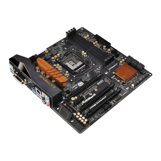
Seite 3: Motherboard-Layout
Z170M Extreme4 Motherboard Layout CPU_FAN1 ATX12V1 USB 3.1 T: USB31_TA_1 B: USB31_TC_1 USB 3.0 Top: T: USB3 RJ-45 B: USB4 CHA_FAN2 CMOS CHA_FAN1 Battery Z170M Extreme4 PCIE1 PCI Express 3.0 PCIE2 Intel PCIE3 Z170 RoHS PCIE4 USB1_2 PANEL1 SPK_CI1 HD_AUDIO1... - Seite 4 No. Description ATX 12V Power Connector (ATX12V1) CPU Fan Connector (CPU_FAN1) 2 x 288-pin DDR4 DIMM Slots (DDR4_A1, DDR4_B1) 2 x 288-pin DDR4 DIMM Slots (DDR4_A2, DDR4_B2) ATX Power Connector (ATXPWR1) Chassis Fan Connector (CHA_FAN2) USB 3.0 Header (USB3_5_6) SATA3 Connector (SATA3_0) SATA3 Connector (SATA3_1) SATA3 Connector (SATA3_2) SATA3 Connector (SATA3_3)
- Seite 5 Z170M Extreme4 I/O Panel No. Description No. Description PS/2 Mouse/Keyboard Port Optical SPDIF Out Port LAN RJ-45 Port* USB 3.0 Ports (USB3_34) Central / Bass (Orange) USB 3.1 Type-A Port (USB31_TA_1) Rear Speaker (Black) USB 3.1 Type-C Port (USB31_TC_1) Line In (Light Blue)
- Seite 6 * There are two LEDs on each LAN port. Please refer to the table below for the LAN port LED indications. ACT/LINK LED SPEED LED LAN Port Activity / Link LED Speed LED Status Description Status Description No Link 10Mbps connection Blinking Data Activity Orange...
-
Seite 7: Chapter 1 Introduction
ASRock’s website without further notice. If you require technical support related to this motherboard, please visit our website for specific information about the model you are using. You may find the latest VGA cards and CPU support list on ASRock’s website as well. ASRock website http://www.asrock.com. -
Seite 8: Specifications
/2400(OC)/2133 non-ECC, un-buffered memory * 3466+(OC) memory frequency can only be achieved when a single memory module is installed (Single channel memory). * Please refer to Memory Support List on ASRock's website for more information. (http://www.asrock.com/) • Max. capacity of system memory: 64GB • Supports Intel®... - Seite 9 • 7.1 CH HD Audio with Content Protection (Realtek ALC1150 Audio Codec) • Premium Blu-ray Audio support • Supports Surge Protection (ASRock Full Spike Protection) • Supports Purity Sound - Nichicon Fine Gold Series Audio Caps - 115dB SNR DAC with Differential Amplifier - TI®...
- Seite 10 • 1 x Optical SPDIF Out Port • 1 x USB 3.1 Type-A Port (10 Gb/s) (ASMedia ASM1142) (Supports ESD Protection (ASRock Full Spike Protection)) • 1 x USB 3.1 Type-C Port (10 Gb/s) (ASMedia ASM1142) (Supports ESD Protection (ASRock Full Spike Protection)) • 4 x USB 3.0 Ports (Intel®...
- Seite 11 * To install Windows® 7 OS, a modified installation disk with xHCI drivers packed into the ISO file is required. Please refer to page 141 for more detailed instructions. * For the updated Windows® 10 driver, please visit ASRock’s website for details: http://www.asrock.com Certifica- • FCC, CE, WHQL...
-
Seite 12: Chapter 2 Installation
Chapter 2 Installation This is a Micro ATX form factor motherboard. Before you install the motherboard, study the configuration of your chassis to ensure that the motherboard fits into it. Pre-installation Precautions Take note of the following precautions before you install motherboard components or change any motherboard settings. -
Seite 13: Installing The Cpu
Z170M Extreme4 2.1 Installing the CPU 1. Before you insert the 1151-Pin CPU into the socket, please check if the PnP cap is on the socket, if the CPU surface is unclean, or if there are any bent pins in the socket. - Seite 15 Z170M Extreme4 Please save and replace the cover if the processor is removed. The cover must be placed if you wish to return the motherboard for after service.
- Seite 16 2.2 Installing the CPU Fan and Heatsink...
- Seite 17 Z170M Extreme4 2.3 Installing Memory Modules (DIMM) This motherboard provides four 288-pin DDR4 (Double Data Rate 4) DIMM slots, and supports Dual Channel Memory Technology. 1. For dual channel configuration, you always need to install identical (the same brand, speed, size and chip-type) DDR4 DIMM pairs.
- Seite 19 Z170M Extreme4 2.4 Expansion Slots (PCI Express Slots) There are 4 PCI Express slots on the motherboard. Before installing an expansion card, please make sure that the power supply is switched off or the power cord is unplugged. Please read the documentation of the expansion card and make necessary hardware settings for the card before you start the installation.
- Seite 20 2.5 Jumpers Setup The illustration shows how jumpers are setup. When the jumper cap is placed on the pins, the jumper is “Short”. If no jumper cap is placed on the pins, the jumper is “Open”. The illustration shows a 3-pin jumper whose pin1 and pin2 are “Short” when a jumper cap is placed on these 2 pins.
- Seite 21 Z170M Extreme4 2.6 Onboard Headers and Connectors Onboard headers and connectors are NOT jumpers. Do NOT place jumper caps over these headers and connectors. Placing jumper caps over the headers and connectors will cause permanent damage to the motherboard. System Panel Header...
- Seite 22 Chassis Intrusion and Please connect the SPEAKER DUMMY Speaker Header chassis intrusion and the DUMMY (7-pin SPK_CI1) chassis speaker to this (see p.1, No. 15) header. SIGNAL DUMMY Serial ATA3 Connectors These six SATA3 (SATA3_0: connectors support SATA see p.1, No. 8) data cables for internal (SATA3_1: storage devices with up to...
- Seite 23 Z170M Extreme4 Front Panel Audio Header This header is for PRESENCE# (9-pin HD_AUDIO1) connecting audio devices MIC_RET OUT_RET (see p.1, No. 20) to the front audio panel. OUT2_L J_SENSE OUT2_R MIC2_R MIC2_L 1. High Definition Audio supports Jack Sensing, but the panel wire on the chassis must support HDA to function correctly.
- Seite 24 ATX Power Connector This motherboard pro- (24-pin ATXPWR1) vides a 24-pin ATX power (see p.1, No. 5) connector. To use a 20-pin ATX power supply, please plug it along Pin 1 and Pin ATX 12V Power This motherboard pro- Connector vides an 8-pin ATX 12V (8-pin ATX12V1) power connector.
- Seite 25 Z170M Extreme4 2.7 M.2_SSD (NGFF) Module Installation Guide The M.2, also known as the Next Generation Form Factor (NGFF), is a small size and versatile card edge connector that aims to replace mPCIe and mSATA. The Ultra M.2 Socket (M2_1) supports M.2 PCI Express module up to Gen3 x4 (32 Gb/s).
- Seite 26 Step 3 Move the standoff based on the module type and length. The standoff is placed at the nut location C by default. Skip Step 3 and 4 and go straight to Step 5 if you are going to use the default nut. Otherwise, release the standoff by hand.
- Seite 27 Z170M Extreme4 M.2_SSD (NGFF) Module Support List Vendor Size Interface Length ADATA 128GB SATA3 2280 AXNS381E-128GM-B ADATA 256GB SATA3 2280 AXNS381E-256GM-B Crucial 120GB SATA3 2280 CT120M500SSD4 Crucial 240GB SATA3 2280 CT240M500SSD4 Intel 80GB SATA3 2280 Intel SSDSCKGW080A401/80G Kingston 120GB SATA3...
- Seite 28 1 Einleitung Vielen Dank, dass Sie sich für das Z170M Extreme4 von ASRock entschieden haben – ein zuverlässiges Motherboard, das konsequent unter der strengen Qualitätskontrolle von ASRock hergestellt wurde. Es liefert ausgezeichnete Leistung mit robustem Design, das ASRock Streben nach Qualität und Beständigkeit erfüllt.
-
Seite 29: Technische Daten
Celeron® der 6. Generation (Sockel 1151) • Digipower-Design • 6-Leistungsphasendesign • Unterstützt Intel® Turbo Boost 2.0-Technologie • Unterstützt CPUs mit freiem Multiplikator der Intel® K-Serie • Unterstützt ASRock BCLK-Übertaktung (voller Bereich) ® Chipsatz • Intel Z170 Speicher • Dualkanal-DDR4-Speichertechnologie • 4 x DDR4-DIMM-Steckplätze... - Seite 30 DVI-D- und HDMI-Ports Audio • 7.1-Kanal-HD-Audio mit Inhaltsschutz (Realtek ALC1150- Audiocodec) • Erstklassige Blu-ray-Audiounterstützung • Unterstützt Überspannungsschutz (ASRock Full Spike Protection) • Unterstützt Purity Sound - Nichicon-Audiokappen der Fine Gold-Serie - 115-dB-SRV-DAC mit Differentialverstärker - TI® NE5532 – erstklassiger Headset-Verstärker (unterstützt...
- Seite 31 • 2 x Gehäuselüfteranschlüsse (4-polig) (intelligente Lüftergeschwindigkeitssteuerung) • 1 x 24-poliger ATX-Netzanschluss • 1 x 8-poliger 12-V-Netzanschluss • 1 x Audioanschluss an Frontblende • 1 x USB 2.0-Stiftleiste (unterstützt 2 USB 2.0-Ports) (unter- stützt Schutz gegen elektrostatische Entladung (ASRock Full Spike Protection))
- Seite 32 • ErP/EuP ready (ErP/EuP ready-Netzteil erforderlich) * Detaillierte Produktinformationen finden Sie auf unserer Webseite: http://www.asrock.com Bitte beachten Sie, dass mit einer Übertaktung, zu der die Anpassung von BIOS-Einstellungen, die Anwendung der Untied Overclocking Technology oder die Nutzung von Übertaktung- swerkzeugen von Drittanbietern zählen, bestimmte Risiken verbunden sind.
-
Seite 33: Jumpereinstellung
Z170M Extreme4 1.3 Jumpereinstellung Die Abbildung zeigt, wie die Jumper eingestellt werden. Wenn die Jumper-Kappe auf den Kontakten angebracht ist, ist der Jumper „kurzgeschlossen“. Wenn keine Jumper- Kappe auf den Kontakten angebracht ist, ist der Jumper „offen“. Die Abbildung zeigt einen 3-poligen Jumper, dessen Kontakt 1 und Kontakt 2 „kurzgeschlossen“... -
Seite 34: Integrierte Stiftleisten Und Anschlüsse
1.4 Integrierte Stiftleisten und Anschlüsse Integrierte Stiftleisten und Anschlüsse sind KEINE Jumper. Bringen Sie KEINE Jumper-Kappen an diesen Stiftleisten und Anschlüssen an. Durch Anbringen von Jumper-Kappen an diesen Stiftleisten und Anschlüssen können Sie das Motherboard dauerhaft beschädigen. Systemblende-Stiftleiste Verbinden Sie PLED+ PLED- (9-polig, PANEL1) - Seite 35 Z170M Extreme4 Gehäuseeingriffs- und Bitte verbinden Sie Gehäu- SPEAKER DUMMY Lautsprecher-Stiftleiste seeingriffsvorrichtung und DUMMY (7-polig, SPK_CI1) den Gehäuselautsprecher (siehe S. 1, Nr. 15) mit dieser Stiftleiste. SIGNAL DUMMY Serial-ATA-III-Anschlüsse Diese sechs SATA-III- (SATA3_0: Anschlüsse unterstützen siehe S. 1, Nr. 8) SATA-Datenkabel für...
- Seite 36 Audiostiftleiste Diese Stiftleiste dient PRESENCE# MIC_RET (Frontblende) dem Anschließen von OUT_RET (9-polig, HD_AUDIO1) Audiogeräten an der (siehe S. 1, Nr. 20) Frontblende. OUT2_L J_SENSE OUT2_R MIC2_R MIC2_L 1. High Definition Audio unterstützt Anschlusserkennung, der Draht am Gehäuse muss dazu jedoch HDA unterstützt. Bitte befolgen Sie zum Installieren Ihres Systems die Anweisungen in unserer Anleitung und der Anleitung zum Gehäuse.
- Seite 37 Z170M Extreme4 ATX-Netzanschluss Dieses Motherboard (24-polig, ATXPWR1) bietet einen 24-poligen (siehe S. 1, Nr. 5) ATX-Netzanschluss. Bitte schließen Sie es zur Nutzung eines 20-poligen ATX-Netzteils entlang Kontakt 1 und Kontakt 13 ATX-12-V-Netzanschluss Dieses Motherboard bietet (8-polig, ATX12V1) einen 8-poligen ATX- (siehe S.
-
Seite 38: Contenu De L'emballage
à modification sans préavis. En cas de modifications du présent document, la version mise à jour sera disponible sur le site Internet ASRock sans notification préalable. Si vous avez besoin d’une assistance technique pour votre carte mère, veuillez visiter notre site Internet pour plus de détails sur le modèle que vous utilisez. -
Seite 39: Spécifications
• Alimentation à 6 phases • Prend en charge la technologie Intel® Turbo Boost 2.0 • Prend en charge les processeurs débloqués de la série K Intel® • Prend en charge l’ o verclocking ASRock BCLK Full-range ® Chipset • Intel Z170 Mémoire... - Seite 40 • Giga PHY Intel® I219V • Prend en charge la fonction Wake-On-LAN • Protection contre les orages/décharges électrostatiques (Pro- tection complète contre les pics ASRock) • Prend en charge la fonction d’ é conomie d’ é nergie Ethernet 802.3az • Prend en charge PXE...
- Seite 41 • 1 x socket Ultra M.2, prend en charge les modules M.2 SATA3 6,0 Gb/s et M.2 PCI Express jusqu'à Gen3 x4 (32 Gb/s) * Prend en charge le kit ASRock U.2 Connecteur • 1 x embase pour port COM • 1 x embase TPM...
- Seite 42 • ErP/EuP Ready (alimentation ErP/EuP ready requise) * pour des informations détaillées de nos produits, veuillez visiter notre site : http://www.asrock.com Il est important de signaler que l’ o vercloking présente certains risques, incluant des modifica- tions du BIOS, l’ a pplication d’une technologie d’ o verclocking déliée et l’utilisation d’ o utils d’...
- Seite 43 Z170M Extreme4 1.3 Configuration des cavaliers (jumpers) L’illustration ci-dessous vous renseigne sur la configuration des cavaliers (jumpers). Lorsque le capuchon du cavalier est installé sur les broches, le cavalier est « court- circuité ». Si le capuchon du cavalier n’ e st pas installé sur les broches, le cavalier est « ouvert ».
- Seite 44 1.4 Embases et connecteurs de la carte mère Les embases et connecteurs situés sur la carte NE SONT PAS des cavaliers. Ne placez JAMAIS de capuchons de cavaliers sur ces embases ou connecteurs. Placer un capuchon de cavalier sur ces embases ou connecteurs endommagera irrémédiablement votre carte mère. Embase du panneau sys- Branchez le bouton de PLED+...
- Seite 45 Z170M Extreme4 Prise DEL d’alimentation Veuillez brancher SPEAKER DUMMY et emplacement sur châssis l'emplacement sur le châs- DUMMY (SPK_CI1 à 7 broches) sis et le haut-parleur du (voir p.1, No. 15) châssis sur ce connecteur. SIGNAL DUMMY Connecteurs Serial ATA3 Ces six connecteurs...
- Seite 46 Embase audio du panneau Cette embase sert au PRESENCE# MIC_RET frontal branchement des appareils OUT_RET (HD_AUDIO1 à 9 audio au panneau audio broches) frontal. OUT2_L (voir p.1, No. 20) J_SENSE OUT2_R MIC2_R MIC2_L 1. L’ a udio haute définition prend en charge la technologie Jack Sensing (détection de la fiche), mais le panneau grillagé...
- Seite 47 Z170M Extreme4 Connecteur d’alimentation Cette carte mère est dotée d’un connecteur (ATXPWR1 à 24 broches) d’alimentation ATX à 24 (voir p.1, No. 5) broches. Pour utiliser une alimentation ATX à 20 broches, veuillez effectuer les branchements sur la Broche 1 et la Broche 13.
-
Seite 48: Contenuto Della Confezione
Web di ASRock senza ulteriore preavviso. Per il supporto tecnico correlato a questa scheda madre, visitare il nostro sito Web per informazioni specifiche relative al modello attualmente in uso. - Seite 49 Pentium®/Celeron® (Socket 1151) • Design Digi Power • Potenza a 6 fasi • Supporta la tecnologia Intel® Turbo Boost 2.0 • Supporto di CPU unlocked Intel® K-Series • Supporta gamma completa overclocking BCLK ASRock ® Chipset • Intel Z170 Memoria • Tecnologia memoria DDR4 Dual Channel...
- Seite 50 • LAN Gigabit 10/100/1000 Mb/s • Giga PHY Intel® I219V • Supporta Wake-On-LAN • Supporto la protezione da fulmini/scariche elettrostatiche (ESD) (protezione completa ASRock dai picchi di corrente) • Supporta Energy Efficient Ethernet 802.3az • Supporta PXE I/O pannello • 1 x porta mouse/tastiera PS/2 posteriore • 1 x porta DVI-D...
- Seite 51 • 1 x porta uscita SPDIF ottico • 1 x Porta USB 3.1 di tipo A (10 Gb/s) (ASMedia ASM1142) (Supporto protezione ESD (protezione ASRock Full Spike)) • 1 x Porta USB 3.1 di tipo C (10 Gb/s) (ASMedia ASM1142) (Supporto protezione ESD (protezione ASRock Full Spike)) • 4 x Porte USB 3.0 (Intel®...
- Seite 52 * Per installare Windows® 7, è necessario un disco di installazi- one modificato con i driver xHCI integrati nel file ISO. Fare riferimento a pagina 141 per altre istruzioni dettagliate. * Per il driver aggiornato di Windows® 10, visitare il sito ASRock all’indirizzo:http://www.asrock.com Certificazioni • FCC, CE, WHQL...
- Seite 53 Z170M Extreme4 1.3 Impostazione jumper L'illustrazione mostra in che modo vengono impostati i jumper. Quando il cappuccio del jumper è posizionato sui pin, il jumper è "cortocircuitato". Se sui pin non è posizionato alcun cappuccio del jumper, il jumper è "aperto". L'illustrazione mostra un jumper a 3 pin i cui pin1 e pin2 sono "cortocircuitati"...
- Seite 54 1.4 Header e connettori sulla scheda Gli header e i connettori sulla scheda NON sono jumper. NON posizionare cappucci del jumper su questi header e connettori. Il posizionamento di cappucci del jumper su header e connettori provocherà danni permanenti alla scheda madre. Header sul pannello del Collegare l'interruttore PLED+...
- Seite 55 Z170M Extreme4 Collegamento altoparlante Collegare l’intrusione tel- SPEAKER DUMMY e intrusione telaio aio e l’altoparlante a questo DUMMY (SPK_CI1 a 7 pin) collegamento. (vedere pag. 1, n. 15) SIGNAL DUMMY Connettori Serial ATA3 Questi sei connettori (SATA3_0: SATA3 supportano cavi vedere pag.
- Seite 56 Header audio pannello Questo header serve a PRESENCE# MIC_RET anteriore collegare i dispositivi OUT_RET (AUDIO1_HD a 9 pin) audio al pannello audio (vedere pag. 1, n. 20) anteriore. OUT2_L J_SENSE OUT2_R MIC2_R MIC2_L 1. L'audio ad alta definizione supporta le funzioni Jack sensing, ma il filo del pannello sullo chassis deve supportare HDA per funzionare correttamente.
- Seite 57 Z170M Extreme4 Connettore di Questa scheda madre è alimentazione ATX dotata di un connettore (ATXPWR1 a 24 pin) di alimentazione ATX (vedere pag. 1, n. 5) a 24 pin. Per utilizzare un'alimentazione ATX a 20 pin, collegarla lungo il pin 1 e il pin 13.
-
Seite 58: Contenido Del Paquete
Si esta documentación sufre alguna modificación, la versión actualizada estará disponible en el sitio web de ASRock sin previo aviso. Si necesita asistencia técnica relacionada con esta placa base, visite nuestro sitio web para obtener información específica sobre el modelo que esté... -
Seite 59: Especificaciones
* Para obtener más información, consulte la lista de memorias compatibles en el sitio web de ASRock. (http://www.asrock.com/) • Capacidad máxima de la memoria del sistema: 64GB • Admite Perfil de memoria extremo de Intel® (XMP) 2.0 • Contacto 15μ... - Seite 60 - Protección de aislamiento PCB (circuito impreso) • Compatible con DTS Connect • LAN Gigabit 10/100/1000 Mb/s • Giga PHY Intel® I219V • Compatible con Wake-On-LAN • Compatible con protección contra rayos y electricidad elec- trostática (protección ASRock Full Spike)
- Seite 61 SATA3_1 se deshabilitará. • 1 x Zócalo Ultra M.2, que admite el módulo SATA3 6,0 Gb/s M.2 y el módulo PCI Express M.2 hasta Gen3 x4 (32 Gb/s) * Admiteel Kit U.2 de ASRock Conector • 1 Cabezal de puerto COM • 1 cabezal TPM...
- Seite 62 • Compatible con ErP/EuP (requiere toma de alimentación com- patible con ErP/EuP) * Para obtener más información acerca del producto, visite nuestro sitio web: http://www.asrock.com Tenga en cuenta que existen ciertos riesgos relacionados con el overclocking (sobreaceleración), incluyendo el ajuste de la configuración del BIOS, aplicando la Tecnología overcloking no vinculada o utilizando las herramientas de overclocking de tercera parte.
- Seite 63 Z170M Extreme4 1.3 Instalación de los puentes La instalación muestra cómo deben instalarse los puentes. Cuando la tapa de puente se coloca en los pines, el puente queda “Corto”. Si no coloca la tapa de puente en los pines, el puente queda “Abierto”. La ilustración muestra un puente de 3 pines cuyo pin 1 y pin 2 son “Cortos”...
- Seite 64 1.4 Conectores y cabezales incorporados Los cabezales y conectores incorporados NO son puentes. NO coloque tapas de puente sobre estos cabezales y conectores. Si coloca tapas de puente sobre los cabezales y conectores dañará de forma permanente la placa base. Cabezal del panel del Conecte el interruptor de PLED+...
- Seite 65 Z170M Extreme4 Cabezal de intrusión de Conecte la intrusión de SPEAKER DUMMY chasis y de altavoces chasis y el altavoz del DUMMY (SPK_CI1 de 7 contactos) chasis a este cabezal. (consulte la pág.1, N.º 15) SIGNAL DUMMY Conectores Serie ATA3...
- Seite 66 Cabezal de audio del panel Este cabezal se utiliza para PRESENCE# MIC_RET frontal conectar dispositivos de OUT_RET (HD_AUDIO1 de 9 pines) audio al panel de audio (consulte la pág.1, N.º 20) frontal. OUT2_L J_SENSE OUT2_R MIC2_R MIC2_L 1. El Audio de Alta Definición (HDA, en inglés) es compatible con el método de sensor de conectores, sin embargo, el cable del panel del chasis deberá...
- Seite 67 Z170M Extreme4 Conector de alimentación Esta placa base contiene un conector de alimentación (ATXPWR1 de 24 pines) ATX de 24 pines. Para (consulte la pág.1, N.º 5) utilizar una toma de alimentación ATX de 20 pines, conéctela en los Pines del 1 al 13.
-
Seite 68: Комплект Поставки
обеспечения BIOS содержимое настоящей документации может быть изменено без предварительного уведомления. При изменении содержимого настоящего документа его обновленная версия будет доступна на веб-сайте ASRock без предварительного уведомления. При необходимости технической поддержки, связанной с материнской платой, посетите веб-сайт и найдите на нем информацию о модели используемой... - Seite 69 • Поддержка процессоров 6- поколения Intel® Core i5/i3/Pentium®/Celeron® (Socket 1151) • Digi Power design • Система питания 6 • Поддержка технологии Intel® Turbo Boost 2.0 • Поддержка полного разгона процессора ASRock BCLK • Поддерживает систему ASRock Hyper BCLK ® • Intel Z170 Чипсет...
- Seite 70 Blu-ray (BD) через порты DVI-D и HDMI Аудио • 7.1-канальный звук высокой четкости HD Audio с защитой данных (аудиокодек Realtek ALC1150) • Поддержка Premium Blu-ray Audio • Защита от перенапряжения (ASRock Full Spike Protection) • Поддержка Purity Sound - Конденсаторы для аудиосистем серии Nichicon Fine Gold - 115 дБ...
- Seite 71 • 1 x оптический выходной SPDIF • 1 x Порт USB 3.1 тип А (10 гбит/с) (ASMedia ASM1142) с панели защитой от электростатического напряжения (ASRock Full Spike Protection) • 1 x Порт USB 3.1 тип С (10 гбит/с) (ASMedia ASM1142) с...
- Seite 72 измененный установочный диск с драйверами xHCI, упакованными в файл ISO. Более подробные инструкции представлены на стр. 141. * Подробные сведения об обновлении драйвера Win- dows® 10 представлены на веб-сайте ASRock:http://www. asrock.com Сертификация • FCC, CE, WHQL • Совместимость с ErP/EuP (необходим блок питания,...
- Seite 73 Z170M Extreme4 * Для получения дополнительной информации об изделии посетите наш веб-сайт: http://www.asrock.com Следует учитывать, что разгон процессора, включая изменение настроек BIOS, применение технологии Untied Overclocking Technology и использование инструментов разгона независимых производителей, сопряжен с определенным риском. Разгон процессора может повлиять на стабильность системы или даже привести к...
- Seite 74 1.4 Колодки и разъемы, расположенные на материнской плате Расположенные на материнской плате колодки и разъемы перемычками НЕ являются. НЕ устанавливайте на эти колодки и разъемы колпачковые перемычки. Установка колпачковых перемычек на эти колодки и разъемы может вызвать неустранимое повреждение материнской платы. Колодка...
- Seite 75 Z170M Extreme4 Колодка с разъемами Предназначена для SPEAKER DUMMY датчика вскрытия корпуса подключения датчика DUMMY и динамика вскрытия корпуса и (7-контактный SPK_CI1) корпусного динамика. (См. стр. 1, № 15) SIGNAL DUMMY Разъемы Serial ATA3 Эти шесть (SATA3_0: разъемов SATA3 См. стр. 1, № 8) предназначены...
- Seite 76 Аудиоколодка передней Эта колодка PRESENCE# панели предназначена MIC_RET OUT_RET (9-контактная, HD_ для подключения AUDIO1) аудиоустройств к OUT2_L (См. стр. 1, № 20) передней аудиопанели. J_SENSE OUT2_R MIC2_R MIC2_L 1. Аудиосистема высокого разрешения поддерживает функцию распознавания разъема, но для е правильной работы необходимо, чтобы провод панели корпуса...
- Seite 77 Z170M Extreme4 Разъем питания АТХ Эта материнская плата (24-контактный, снабжена 24-контактным ATXPWR1) разъемом питания АТХ. (См. стр. 1, № 5) Чтобы использовать 20-контактный разъем питания ATX, подключите его вдоль контакта 1 и контакта 13. Разъем питания Эта материнская плата АТХ 12 В...
-
Seite 78: Conteúdo Da Embalagem
Se precisar de assistência técnica relacionada a esta placa principal, visite o nosso site para obter informações específicas sobre o modelo que estiver utilizando. Você também poderá encontrar a lista de placas VGA e CPU mais recentes suportadas no site da ASRock. Site da ASRock http://www.asrock.com. - Seite 79 Pentium®/Celeron® (Soquete 1151) • Design Digi Power • Design com 6 fases de alimentação • Suporta a tecnologia Intel® Turbo Boost 2.0 • Suporta Overclocking total ASRock BCLK • Suporta Motor ASRock Hyper BCLK ® • Intel Z170 Chipset Memória...
- Seite 80 - Tecnologia de drive direto - Blindagem de isolamento PCB • Suporta a tecnologia DTS Connect • LAN Gigabit a 10/100/1000 Mb/s • Giga PHY Intel® I219V • Suporta Wake-On-LAN • Suporta Proteção contra Relâmpago/EDS (Proteção Total Con- tra Picos ASRock)
- Seite 81 • 1 x Porta de saída SPDIF ótica • 1 x Porta USB 3.1 Tipo A (10 Gb/s) (ASMedia ASM1142) (Suporta Proteção ESD (Proteção Total Contra Picos ASRock)) • 1 x Porta USB 3.1 Tipo C (10 Gb/s) (ASMedia ASM1142) (Suporta Proteção ESD (Proteção Total Contra Picos ASRock))
- Seite 82 ErP/EuP) * Para obter informações detalhadas sobre o produto, por favor, visite o nosso site: http://www.asrock.com Por favor, observe que existe um certo risco envolvendo overclocking, incluindo o ajuste das definições na BIOS, a aplicação de tecnologia Untied Overclocking ou a utilização de ferra- mentas de overclocking de terceiros.
- Seite 83 Z170M Extreme4 1.3 Configuração dos jumpers A imagem abaixo mostra como os jumpers são configurados. Quando a tampa do jumper é colocada nos pinos, o jumper é "Curto". Se não for colocada uma tampa de jumper nos pinos, o jumper é "Aberto". A imagem mostra um jumper de 3 pinos cujos pino1 e pino2 estão "Curtos"...
- Seite 84 1.4 Suportes e conectores onboard Os conectores e suportes onboard NÃO são jumpers. NÃO coloque tampas de jumpers sobre estes terminais e conectores. Colocar tampas de jumpers sobre os terminais e conectores irá causar danos permanentes à placa-mãe. Suporte do painel de Ligue o botão de PLED+ PLED-...
- Seite 85 Z170M Extreme4 Intrusão do Chassi e Conecte a instrusão do SPEAKER DUMMY Cabeçote de Autofalante chassi e autofalante do DUMMY (SPK_CI1 de 7 pinos) chassia este cabeçote. (ver p.1, N.º 15) SIGNAL DUMMY Conectores série ATA3 Estes seis conectores (SATA3_0: SATA3 suportam ver p.1, N.º...
- Seite 86 Suporte de áudio do painel Este suporte destina-se à PRESENCE# frontal conexão dos dispositivos MIC_RET OUT_RET (HD_AUDIO1 de 9 pinos) de áudio no painel de (ver p.1, N.º 20) áudio frontal. OUT2_L J_SENSE OUT2_R MIC2_R MIC2_L 1. O Áudio de alta definição suporta Sensor de Adaptador, mas o fio do painel no chassi deverá...
- Seite 87 Z170M Extreme4 Conector de alimentação Esta placa-mãe inclui um conector de alimentação (ATXPWR1 de 24 pinos) ATX de 24 pinos. Para (ver p.1, N.º 5) utilizar uma fonte de alimentação ATX de 20 pinos, introduza-a no Pino 1 e Pino 13.
-
Seite 88: Ambalaj İçeriği
Bu dokümantasyon üzerinde herhangi bir değişiklik yapılması halinde, güncellenmiş sürüm, herhangi bir bildirim yapılmaksızın ASRock'ın web sitesinde yer alacaktır.. Bu anakart ile ilgili olarak teknik destek almak istiyorsanız, lütfen kullandığınız model hakkında özel bilgiler için web sitemizi ziyaret edin. - Seite 89 (OC)/2133 ECC olmayan, arabelleksiz bellek destekler * 3466+(OC) bellek frekansı yalnızca tek bir bellek modülü takıldığında elde edilebilir (tek kanal bellek). * Ayrıntılı bilgi için ASRock'ın web sitesindeki Bellek Desteği Listesine bakın. (http://www.asrock.com/) • Maksimum sistem belleği kapasitesi: 64GB • Intel® Üstün Bellek Profili (XMP) 2.0 destekler • DIMM Yuvalarında 15μ...
- Seite 90 (BD) kayıttan yürütme destekler • İçerik Koruma Özelliği ile 7.1 CH HD Ses (Realtek ALC1150 Ses Codec Bileşeni) • Üstün Blu-ray Ses desteği • Dalgalanma Koruması Destekler (ASRock Tam Ani Gerilim Koruması) • Purity Sound 3 destekler - Nichicon Fine Gold Serisi Ses Kapakları...
- Seite 91 • 1 x Optik SPDIF Çıkışı Bağlantı Noktası • 1 x USB 3.1 Tip A Bağlantı Noktası (10 Gb/sn.) (ASMedia ASM1142) (ESD Koruması Destekler (ASRock Tam Ani Gerilim Koruması)) • 1 x USB 3.1 Tip C Bağlantı Noktası (10 Gb/sn.) (ASMedia ASM1142) (ESD Koruması...
- Seite 92 • ErP/EuP için hazır (ErP/EuP için hazır güç beslemesi gerek- lidir) * Detaylı ürün bilgisi için, lütfen web sitemizi ziyaret edin: http://www.asrock.com Lütfen, BIOS ayarlarını düzenleme, Bağımsız Hız Aşırtma Teknolojinin uygulanması ya da üçüncü kişilerin hız aşırtma araçlarının kullanılması da dahil olmak üzere tüm hız aşırtma işlemlerinin belirli bir risk taşıdığını...
- Seite 93 Z170M Extreme4 1.3 Bağlantı Teli Kurulumu Çizim, bağlantı tellerinin kurulumunu göstermektedir. Tel kapağı, pimlerin üzerine yerleştirildiğinde, tel "Kısa" olur. Pimlerin üzerinde tel kapağı bulunmadığında, tel "Açık" olur. Çizim, pin1 ve pin2 alanları "Kısa" olan ve bu iki pim üzerinde bir bağlantı...
- Seite 94 1.4 Ekli Bağlantılar ve Bağlayıcılar Ekli bağlantılar ve bağlayıcılar bağlantı teli değildir. Bağlantı teli kapaklarını bu bağlantı ve bağlayıcılar üzerine yerleştirmeyin. Bağlantı teli kapaklarının bağlantılar ile bağlayıcılar üzerine yerleştirilmesi, anakarta kalıcı hasar verebilir. Sistem Paneli Bağlantısı Güç anahtarını bağlayın, PLED+ PLED- (9-pin PANEL1) kasa üzerindeki anahtar ile...
- Seite 95 Z170M Extreme4 Kasa Yetkisiz Erişim ve Lütfen kasa yetkisiz erişim SPEAKER DUMMY Hoparlör Bağlantısı ve kasa hoparlörünü bu DUMMY (7 pimli SPK_CI1) bağlantıya takın. (bkz. sf.1, No. 15) SIGNAL DUMMY Seri ATA3 Bağlayıcıları Bu altı SATA3 bağlayıcısı, (SATA3_0: veri aktarım hızı 6,0 Gb/ bkz.
- Seite 96 Ön Panel Ses Bağlantısı Bu bağlantı, ses aygıtlarının PRESENCE# (9-pin HD_AUDIO1) MIC_RET ön ses paneline bağlanması OUT_RET (bkz. sf.1, No. 20) içindir. OUT2_L J_SENSE OUT2_R MIC2_R MIC2_L 1. Yüksek Tanımlı Ses, Jak Algılama özelliğini destekler, ancak bu işlevin düzgün çalışabilmesi için kasa üzerindeki panel kablosunun HDA işlevini desteklemesi gerekmektedir.
- Seite 97 Z170M Extreme4 ATX Güç Bağlayıcısı Bu anakart, 24-pin (24-pin ATXPWR1) ATX güç bağlayıcısı (bkz. sf.1, No. 5) sağlamaktadır. 20-pin ATX güç beslemesi kullanmak için, lütfen Pin 1 ve Pin 13'e bağlayın. ATX 12V Güç Bağlayıcısı Bu anakart, 8-pin ATX (8-pin ATX12V1) 12V güç...
- Seite 98 버전은 ASRock 의 웹사이트에서 추가 통지 없이 제공됩니다 . 이 마더보드와 관련하여 기술적 지원이 필요한 경우 , 당사의 웹사이트를 방문하여 사용 중인 모델에 대한 구체적 정보를 구하십시오 . ASRock 의 웹사이트에서는 최신 VGA 카드와 CPU 지원 목록도 찾을 수 있습니다 . ASRock 웹사이트 http://www.asrock.com.
- Seite 99 (OC)/2133 비 -ECC, 비버퍼링 메모리 지원 * 단일 메모리 모듈 ( 단일 채널 메모리 ) 을 설치할 때만 3466+(OC) 메모리 주파수를 얻을 수 있습니다 . * 추가 정보를 원하시면 ASRock 웹사이트에 있는 메모리 지원 목록을 참조하십시오 . (http://www.asrock.com/) • 시스템 메모리 최대 용량 : 64GB • Intel®...
- Seite 100 • DTS 연결 지원 • Gigabit LAN 10/100/1000 Mb/s • Giga PHY Intel® I219V • Wake-On-LAN 지원 • 번개 /ESD 보호 지원 (ASRock 풀 스파이크 보호 ) • 절전형 이더넷 802.3az 지원 • PXE 지원 • PS/2 마우스 / 키보드 포트 1 개...
- Seite 101 • USB 3.1 타입 C 포트 1 개 (10 Gb/s) (ASMedia ASM1142) (ESD 보호 지원 (ASRock 풀 스파이크 보호 )) • USB 3.0 포트 4 개 (Intel® Z170)(ESD 보호 지원 (ASRock 풀 스파이크 보호 )) • LED 장착 RJ-45 LAN 포트 1 개 (ACT/LINK LED 및 SPEED LED) • HD 오디오...
- Seite 102 인증 • ErP/EuP 사용 가능 (ErP/EuP 사용 가능 전원공급장치 필요 ) * 자세한 제품 정보에 대해서는 당사 웹사이트를 참조하십시오 : http://www.asrock.com BIOS 설정을 조정하거나 Untied Overclocking Technology 를 적용하거나 타업체의 오 버클로킹 도구를 사용하는 것을 포함하는 오버클로킹에는 어느 정도의 위험이 따른...
- Seite 103 Z170M Extreme4 1.3 점퍼 설정 그림은 점퍼를 어떻게 설정하는지 보여줍니다 . 점퍼 캡을 핀에 씌우면 점퍼가 “단락” 됩니다 . 점퍼 캡을 핀에 씌우지 않으면 점퍼가 “단선”됩니다 . 그림은 3 핀 점퍼를 보여주며 핀 1 과 핀 2 는 점퍼 캡을 씌울 때 “단락”됩니다 .
- Seite 104 1.4 온보드 헤더 및 커넥터 온보드 헤더와 커넥터는 점퍼가 아닙니다 . 점퍼 캡을 온보드 헤더와 커넥터에 씌우 지 마십시오 . 점퍼 캡을 온보드 헤더와 커넥터에 씌우면 마더보드가 영구적으로 손 상됩니다 . 섀시의 전원 스위치 , 시스템 패널 헤더 PLED+ PLED- (9 핀...
- Seite 105 Z170M Extreme4 SPEAKER 섀시 침입 및 스피커 헤더 섀시 침입 및 섀시 스 DUMMY (7 핀 SPK_CI1) 피커를 이 헤더에 연결 DUMMY (1 페이지 , 15 번 항목 참조 ) 하십시오 . SIGNAL DUMMY 시리얼 ATA3 커넥터 이들 6 개의 SATA3 커...
- Seite 106 전면 패널 오디오 헤더 이 헤더는 오디오 장치 PRESENCE# MIC_RET (9 핀 HD_AUDIO1) 를 전면 오디오 패널에 OUT_RET (1 페이지 , 20 번 항목 참조 ) 연결하는 데 사용됩니 다 . OUT2_L J_SENSE OUT2_R MIC2_R MIC2_L 1. 고음질 오디오는 잭 감지를 지원하지만 올바르게 작동하려면 섀시의 패널 와이어 가...
- Seite 107 Z170M Extreme4 ATX 전원 커넥터 이 마더보드에는 (24 핀 ATXPWR1) 24 핀 ATX 전원 (1 페이지 , 5 번 항목 커넥터가 탑재되어 참조 ) 있습니다 . 20 핀 ATX 전원공급장치를 사용하려면 핀 1 과 핀 13 을 따라 연결하십시오 .
- Seite 108 アルの内容は予告なしに変更するこ とがあります。 このマニュアルの内容に変更 があった場合には、 更新されたバージョンは、 予告なく アスロックのウェブサイ トか ら入手できるようになります。 このマザーボードに関する技術的なサポートが必要 な場合には、 ご使用のモデルについての詳細情報を、 当社のウェブサイ トで参照く ださい。 ASRock のウェブサイ トでは、 最新の VGA カードおよび CPU サポート一覧 もご覧になれます。 ASRock ウェブサイ ト http://www.asrock.com. 1.1 パッケージの内容 • ASRock Z170M Extreme4 マザーボード (マイクロ ATX フォームファクター) • ASRock Z170M Extreme4 クイックインストールガイ ド...
- Seite 109 • DDR4 3466+(OC)*/3200(OC)/2933(OC)/2800(OC)/2400 (OC)/2133 ノン ECC、 アンバッファードメモリに対応 * 3466+(OC) メモリ周波数を達成できるのは、 シングルメモ リモジュールが取り付けられている場合だけです (シング ルチャンネルメモリ) 。 * 詳細については、 ASRock ウェブサイ トのメモリーサポー ト一覧を参照してく ださい。 (http://www.asrock.com/) • システムメモリの最大容量 : 64GB • Intel® エクストリームメモリプロファイル (XMP) 2.0 に対 応 • DIMM スロッ トに 15 μゴールドコンタク トを採用...
- Seite 110 Ohms までのヘッ ドセッ トに対応) - ピュアなパワー入力 - ダイレク ト ドライブテク ノロジー - PCB 絶縁シールド • DTS 接続をサポート • ギガビッ ト LAN 10/100/1000 Mb/ 秒 • ギガ PHY Intel® I219V • ウェイクオンランをサポート • 雷 / 静電気放電 (ESD) 保護に対応 (ASRock 完全スパイ ク保護)...
- Seite 111 • 1 x HDMI ポート • 1 x 光 SPDIF 出力ポート • 1 x USB 3.1 Type-A ポート (10 Gb/s) (ASMedia ASM1142) (静電気放電 (ESD) 保護に対応 (ASRock 完全スパイ ク保護) ) • 1 x USB 3.1 Type-C ポート (10 Gb/s) (ASMedia ASM1142)...
- Seite 112 64-bit * Windows® 7 OS をインストールするために、 xHCI ドライ バが ISO ファイルに含まれる変更されたインストールディ スクが必要です。 詳しい説明については 141 ページを参照 してく ださい。 * 更新された Windows® 10 ドライバについては、 ASRock の ウェブサイ トで詳細をご確認く ださい : http://www.asrock. • FCC、 CE、 WHQL 認証 • ErP/EuP Ready ( ErP/EuP 対応電源供給装置が必要で...
- Seite 113 1.3 ジャンパー設定 このイラストは、 ジャンパーの設定方法を示しています。 ジャンパーキャップがピ ンに被さっていると、 ジャンパーは 「ショート」 です。 ジャンパーキャップがピンに被 さっていない場合には、 ジャンパーは 「オープン」 です。 この図は 3ピンのジャンパー を表し、 ジャンパーキャップがピン 1 とピン 2 に被さっているとき、 これらのピンは 「ショート」 です。 CMOS クリアジャンパー (CLRMOS1) デフォルト CMOS のクリア (p.1、 No. 16 参照) CLRCMOS1 を使って CMOS 内のデータをクリアできます。 ク リアして、 デフォル ト設定にシステムパラメーターをリセッ...
- Seite 114 1.4 オンボードのヘッダーとコネクター オンボードヘッダーとコネクターはジャンパーではありません。 これらヘッダーと コネクターにはジャンパーキャップを被せないでく ださい。 ヘッダーおよびコネク ターにジャンパーキャップを被せると、 マザーボードに永久損傷が起こるこ とがあ ります。 システムパネルヘッダー 電源スイッチを接続し、 PLED+ PLED- (9 ピンパネル 1) スイッチをリセッ トし、 下 PWRBTN# (p.1、 No. 14 参照) 記のピン割り当てに従っ て、 シャーシのシステムス テータス表示ランプをこ RESET# HDLED- のヘッダーにセッ トしま HDLED+ す。 ケーブルを接続する ときには、 ピンの+と−に 気をつけてく ださい。 PWRBTN (電源スイッチ)...
- Seite 115 シャーシイントルージョン シャーシイントルージョン SPEAKER DUMMY とスピーカーヘッダー とシャーシスピーカーを DUMMY (7 ピン SPK_CI1) このヘッダーに接続して (p.1、 No. 15 参照) く ださい。 SIGNAL DUMMY シリアル ATA3 コネクター これら 6 つの SATA3 コネ クターは、 最高 6.0 Gb/ 秒 (SATA3_0: p.1、 No. 8 参照) のデータ転送速度で内部 ストレージデバイス用の (SATA3_1: p.1、...
- Seite 116 フロントパネルオーディ このヘッダーは、 フロント PRESENCE# オヘッダー MIC_RET オーディオパネルにオー OUT_RET (9 ピン HD_AUDIO1) ディオデバイスを接続す (p.1、 No. 20 参照) るためのものです。 OUT2_L J_SENSE OUT2_R MIC2_R MIC2_L 1. ハイディフィニションオーディオはジャックセンシングをサポートしていますが、 正しく機能するためには、 シャーシのパネルワイヤーが HDA をサポートしてい るこ とが必要です。 お使いのシステムを取り付けるには、 当社のマニュアルおよ びシャーシのマニュアルの指示に従ってく ださい。 2. AC 97 オーディオパネルを使用する場合には、 次のステップで、 前面パネルオー ディオヘッダーに取り付けてく...
- Seite 117 ATX 電源コネクタ このマザーボードは 24 ピ (24 ピン ATXPWR1) ン ATX 電源コネクタを提 (p.1、 No. 5 参照) 供します。 20 ピンの ATX 電源を使用するには、 ピ ン 1 と 13 番に合わせて 接続してく ださい。 ATX 12V 電源コネクター このマザーボードは 8 ピ (8 ピン ATX12V1) ン ATX12V 電源コネク (p.1、...
- Seite 118 另外进行通知。如果您需要与此主板相关的技术支持,请访问我们的网站以具体了 解所用型号的信息。您也可以在华擎网站上找到最新 VGA 卡和 CPU 支持列表。华 擎 网站 http://www.asrock.com。 1.1 包装清单 • 华擎 Z170M Extreme4 主板(Micro ATX 规格尺寸) • 华擎 Z170M Extreme4 快速安装指南 • 华擎 Z170M Extreme4 支持光盘 • 2 x 串行 ATA (SATA) 数据线(选购) • 1 x I/O 面板...
- Seite 119 • 支持第 6 代 Intel® Core i7/i5/i3/Pentium®/Celeron® 处理器 (Socket 1151) • Digi Power(帝捷)设计 • 6 电源相设计 • 支持 Intel® Turbo Boost 2.0 技术 • 支持 Intel® K 系列不锁频 CPU • 支持 ASRock 超级外频芯片 • Intel ® Z170 芯片集 • 双通道 DDR4 内存技术 内存...
- Seite 120 • Pixel Shader 5.0、DirectX 12 • 最大共享内存 1792MB • 双图形输出 : 通过独立显示控制器支持 DVI-D 和 HDMI 端口 • 支持 HDMI,最大分辨率可达 4K x 2K (4096x2160) @ 24Hz / (3840x2160) @ 30Hz • 支持 DVI-D,60Hz 时最大分辨率达 1920x1200 • 通过 HDMI 端口(需要兼容的 HDMI 显示器)支持 Auto Lip Sync、Deep Color (12bpc), xvYCC 和...
- Seite 121 Z170M Extreme4 • 1 x USB 3.1 A 类型端口 (10 Gb/s)(ASMedia ASM1142)(支 持 ESD 保护,即华擎全防护) • 1 x USB 3.1 C 类型端口 (10 Gb/s)(ASMedia ASM1142)(支持 ESD 保护,即华擎全防护) • 4 x USB 3.0 端口(Intel® Z170,支持 ESD 保护,即华擎全 防护) • 1 x RJ-45 LAN 端口,带 LED(ACT/LINK LED 和 SPEED LED)...
- Seite 122 • Microsoft® Windows® 10 64-bit / 8.1 64-bit / 7 32-bit / 7 64-bit 操作系统 * 要安装 Windows® 7 OS,需要 xHCI 驱动程序已封闭到 ISO 文件的经修改的安装盘。请参考第 141 页了解详情。 * 有关已更新的 Windows® 10 驱动程序,请访问华擎网站了解 详情 :http://www.asrock.com • FCC、CE、WHQL 认证 • ErP/EuP 支持(需要支持 ErP/EuP 的电源) * 有关详细产品信息,请访问我们的网站:http://www.asrock.com 须认识到超频会有一定风险,包括调整...
- Seite 123 Z170M Extreme4 1.3 跳线设置 此图显示如何设置跳线。将跳线帽装到这些针脚上时,跳线 “短接”。如果这 些针脚上没有装跳线帽,跳线 “开路”。此图显示 3 针跳线,当跳线帽装在针 脚 1 和针脚 2 上,它们“短接”。 清除 CMOS 跳线 (CLRMOS1) 清除 CMOS 默认 (见第 1 页,第 16 个) CLRMOS1 允许您清除 CMOS 中的数据。要清除和重置系统参数到默认设 置,请关闭计算机,从电源上拔下电源线插头。等候 15 秒后,使用跳线帽将 CLRMOS1 上的针脚 2 和针脚 3 短接 5 秒。但是,请勿在更新 BIOS 后立即清...
- Seite 124 1.4 板载接脚和接口 板载接脚和接口不是跳线。 不要将跳线帽装到这些接脚和接口上。 将跳线帽装 到这些接脚和接口上将会对主板造成永久性损坏。 系统面板接脚 按照下面的针脚分配, PLED+ PLED- (9 针 PANEL1) PWRBTN# 将机箱上的电源开关、 (见第 1 页, 第 14 个) 重置开关和系统状态指 示灯连接到此接脚。在 RESET# 连接线缆前请记下正负 HDLED- 针脚。 HDLED+ PWRBTN(电源开关): 连接到机箱前面板上的电源开关。您可以配置使用电源开关关闭系统的方式。 RESET(重置开关): 连接到机箱前面板上的重置开关。如果计算机死机,无法执行正常重新启动,按重 置开关重新启动计算机。 PLED(系统电源 LED): 连接到机箱前面板上的电源状态指示灯。系统操作操作时,此 LED 亮起。系统处在 S1/S3 睡眠状态时, 此 LED 闪烁。 系统处在 S4 睡眠状态或关机 (S5) 时, 此 LED 熄灭。 HDLED(硬盘活动...
- Seite 125 Z170M Extreme4 机箱侵入和扬声器接脚 请将机箱侵入和机箱扬 SPEAKER DUMMY (7 针 SPK_CI1) 声器连接到到此接脚。 DUMMY (见第 1 页,第 15 个) SIGNAL DUMMY 串行 ATA3 接口 这六个 SATA3 接口支持 (SATA3_0: 最高 6.0 Gb/s 数据传输 见第 1 页, 第 8 个) 速率的内部存储设备的 (SATA3_1: SATA 数据线。 见第 1 页, 第 9 个)...
- Seite 126 前面板音频接脚 此接脚用于将音频设备 PRESENCE# (9 针 HD_AUDIO1) MIC_RET 连接到前音频面板。 OUT_RET (见第 1 页,第 20 个) OUT2_L J_SENSE OUT2_R MIC2_R MIC2_L 1. 高清音频支持插孔感测,但机箱上的面板连线必须支持 HDA 才能正常工作。 请按照我们的手册和机箱手册的说明安装系统。 2. 如果您使用 AC’97 音频面板,请按照以下步骤将它安装到前面板音频接脚: A. 将 Mic_IN (MIC) 连接到 MIC2_L。 B. 将 Audio_R (RIN) 连接到 OUT2_R,将 Audio_L (LIN) 连接到 OUT2_L。 C.
- Seite 127 Z170M Extreme4 ATX 12V 电源接口 此主板提供 8 针 ATX (8 针 ATX12V1) 12V 电源接口。要使用 4 (见第 1 页,第 1 个) 针 ATX 电源,请沿针脚 1 和针脚 5 插接它。 此 COM1 接脚支持串行 串行端口接脚 (9 针 COM1) 端口模块。 (见第 1 页,第 19 个)...
- Seite 128 电子信息产品污染控制标示 依据中国发布的「电子信息产品污染控制管理办法」及 SJ/T 11364-2006「电子 信息产品污染控制标示要求」,电子信息产品应进行标示,藉以向消费者揭露 产品中含有的有毒有害物质或元素不致发生外泄或突变从而对环境造成污染或 对人身、财产造成严重损害的期限。依上述规定,您可于本产品之印刷电路板 上看见图一之标示。图一中之数字为产品之环保使用期限。由此可知此主板之 环保使用期限为 10 年。 图一 有毒有害物质或元素的名称及含量说明 若您欲了解此产品的有毒有害物质或元素的名称及含量说明,请参照以下表格 及说明。 有害物质或元素 部件名称 铅 (Pb) 镉 (Cd) 汞 (Hg) 六价铬 (Cr(VI)) 多溴联苯 (PBB) 多溴二苯醚 (PBDE) 印刷电路板 及电子组件 外部信号连 接头及线材 O: 表示该有毒有害物质在该部件所有均质材料中的含量均在 SJ/T 11363-2006 标准规定 的限量要求以下。 X: 表示该有毒有害物质至少在该部件的某一均质材料中的含量超出 SJ/T 11363-2006 标准 规定的限量要求,然该部件仍符合欧盟指令...
- Seite 129 知。如本文件有任何修改,可至華擎網站逕行取得更新版本,不另外通知。若您需 要與本主機板相關的技術支援,請上我們的網站瞭解有關您使用機型的特定資訊。 您也可以在華擎網站找到最新的 VGA 卡及 CPU 支援清單。華擎網站 http://www. asrock.com。 1.1 包裝內容 • 華擎 Z170M Extreme4 主機板(Micro ATX 尺寸) • 華擎 Z170M Extreme4 快速安裝指南 • 華擎 Z170M Extreme4 支援光碟 • 2 x Serial ATA (SATA) 資料纜線(選用) • 1 x I/O 面板外罩...
- Seite 130 • 支援第 6 代 Intel® Core i7/i5/i3/Pentium®/Celeron® 處理器 (插座 1151) • 數位電源設計 (Digi Power) • 6 電源相位設計 • 支援 Intel® Turbo Boost 2.0 技術 • 支援華擎 BCLK 全域電壓超頻 • 支援 ASRock 超級外頻晶片 • Intel ® Z170 晶片組 • 雙通道 DDR4 記憶體技術 記憶體...
- Seite 131 Z170M Extreme4 • Pixel Shader 5.0,DirectX 12 • 最大共用記憶體 1792MB • 雙圖形輸出:透過獨立顯示控制器支援 DVI-D 及 HDMI 連接埠 • 支援最高可達 4K x 2K (4096x2160) @ 24Hz / (3840x2160) @ 30Hz 解析度的 HDMI • 支援最高達 1920x1200 @ 60Hz 解析度的 DVI-D • 支援使用 HDMI 連接埠(需相容於 HDMI 監視器)的...
- Seite 132 • 1 x USB 3.1 A 類型連接埠 (10 Gb/s) (ASMedia ASM1142) ( 支 援靜電保護(華擎全防護)) • 1 x USB 3.1 C 類型連接埠 (10 Gb/s) (ASMedia ASM1142) ( 支 援靜電保護(華擎全防護)) • 4 x USB 3.0 連接埠 (Intel® Z170)(支援靜電保護(華擎全防 護)) • 1 x RJ-45 LAN 連接埠,含 LED(ACT/LINK LED 及 SPEED LED)...
- Seite 133 Z170M Extreme4 • CPU /機殼溫度感應 硬體監視 • CPU /機殼風扇轉速計 器 • CPU /機殼靜音風扇(依 CPU 溫度自動調整機殼風扇速 度) • CPU /機殼風扇多重速度控制 • 機殼開啟偵測 • 電壓監控:+12V、+5V、+3.3V、CPU Vcore、DRAM、 VPPM、PCH 1.0V、VCCIO、VCCSA • Microsoft® Windows® 10 64 位元/ 8.1 64 位元/ 7 32 位元/ 作業系統 7 64 位元...
- Seite 134 1.3 跳線設定 圖例顯示設定跳線的方式。當跳線帽套在針腳上時,該跳線為「短路」。若沒 有跳線帽套在針腳上,該跳線為「開啟」。圖例顯示當 3-pin 跳線的跳線蓋套 在 pin1 及 pin2 時,這兩個針腳皆為「短路」。 清除 CMOS 跳線 (CLRMOS1) 清除 CMOS 預設 (請參閱第 1 頁,編號 16) 您可利用 CLRMOS1 清除 CMOS 中的資料。若要清除及重設系統參數為預設 設定,請先關閉電腦電源,再拔下電源供應器的電源線。在等待 15 秒後, 請使用跳線帽讓 CLRMOS1 上的 pin2 及 pin3 短路約 5 秒。不過,請不要在更 新 BIOS 後立即清除 CMOS。若您需在更新 BIOS 後立即清除 CMOS,則必須 先重新啟動系統,然後於進行清除...
- Seite 135 Z170M Extreme4 1.4 板載排針及接頭 板載排針及接頭都不是跳線。請勿將跳線帽套在這些排針及接頭上。將跳線帽套在 排針及接頭上,將造成主機板永久性的受損。 系統面板排針 請依照以下的針腳排 PLED+ PLED- (9-pin PANEL1) PWRBTN# 列將機殼上的電源開 (請參閱第 1 頁, 編號 14) 關、重設開關及系統 狀態指示燈連接至此 RESET# 排針。在連接纜線之 HDLED- 前請注意正負針腳。 HDLED+ PWRBTN ( 電源開關 ): 連接至機殼前面板上的電源開關。您可設定使用電源開關關閉系統電源的方式。 RESET ( 重設開關 ): 連接至機殼前面板上的重設開關。若電腦凍結且無法執行正常重新啟動,按下重設 開關即可重新啟動電腦。 PLED ( 系統電源 LED):...
- Seite 136 機殼防護排針 機殼防護排針連接 SPEAKER DUMMY (7-pin SPK_CI1) 至此排針。 DUMMY (請參閱第 1 頁,編號 15) SIGNAL DUMMY Serial ATA3 接頭 這六組 SATA3 接頭 (SATA3_0: 皆支援內部儲存裝 請參閱第 1 頁,編號 8) 置的 SATA 資料纜 (SATA3_1: 線,最高可達 6.0 請參閱第 1 頁,編號 9) Gb/s 資料傳輸率。 (SATA3_2: * 若 M2_1 為 SATA 請參閱第...
- Seite 137 Z170M Extreme4 前面板音訊排針 本排針適用於連接 PRESENCE# MIC_RET (9-pin HD_AUDIO1) 音訊裝置至前面板 OUT_RET (請參閱第 1 頁,編號 20) 音訊。 OUT2_L J_SENSE OUT2_R MIC2_R MIC2_L 1. 高解析度音訊支援智慧型音效介面偵測 (Jack Sensing),但機殼上的面板線必 須支援 HDA 才能正確運作。請依本手冊及機殼手冊說明安裝系統。 2. 若您使用 AC’97 音訊面板,請按照以下步驟安裝至前面板音訊排針: A. 將 Mic_IN (MIC) 連接至 MIC2_L。 B. 將 Audio_R (RIN) 連接至 OUT2_R 且將 Audio_L (LIN) 連接至 OUT2_L。...
- Seite 138 ATX 電源接頭 本主機板配備一組 (24-pin ATXPWR1) 24-pin ATX 電源接 (請參閱第 1 頁,編號 5) 頭。若要使用 20- pin ATX 電源供應 器,請插入 Pin 1 及 Pin 13。 ATX 12V 電源接頭 本主機板配備一組 (8-pin ATX12V1) 8-pin ATX 12V 電 (請參閱第 1 頁,編號 1) 源接頭。若要使用 4-pin ATX 電源供應 器,請插入...
- Seite 139 (OC)/2400(OC)/2133 non-ECC, memori tanpa buffer * Frekuensi memori 3466+(OC) hanya dapat dicapai bila satu modul memori dipasang (satu memori kanal). * Lihat Daftar Dukungan Memori pada situs web ASRock untuk informasi selengkapnya. (http://www.asrock.com/) • Kapasitas maksimum memori sistem: 64GB • Mendukung Intel® Extreme Memory Profile (XMP) 2.0 • 15μ...
- Seite 140 Audio • Audio HD 7.1 CH dengan Perlindungan Konten (Realtek ALC1150 Audio Codec) • Mendukung Audio Blu-ray Premium • Mendukung Perlindungan Lonjakan Arus (ASRock Full Spike Protection) • Mendukung Purity Sound - Nichicon Fine Gold Series Audio Caps - 115dB SNR DAC dengan Amplifier Diferensial - TI®...
- Seite 141 • 1 x Port HDMI • 1 x Port SPDIF Out Optik • 1 x USB 3.1 Port Tipe A (10 Gb/s) (ASMedia ASM1142) (Mendukung Perlindungan ESD (Perlindungan ASRock Full Spike)) • 1 x USB 3.1 Port Tipe C (10 Gb/s) (ASMedia ASM1142)
- Seite 142 • FCC, CE, WHQL • Siap untuk ErP/EuP (memerlukan catu daya untuk ErP/EuP) * Untuk informasi tentang produk rinci, kunjungi situs web kami: http://www.asrock.com Perlu diketahui, overclocking memiliki risiko tertentu, termasuk menyesuaikan pengaturan pada BIOS, menerapkan Teknologi Untied Overclocking, atau menggunakan alat overclocking pihak ketiga.
- Seite 143 Intel® USB 3.0 eXtensible Host Controller (xHCI) drivers packed into the ISO file. Requirements A Windows® 7 installation disk or USB drive • USB 3.0 drivers (included in the ASRock Support CD or website) • A Windows® PC • Win7 USB Patcher (included in the ASRock Support CD or website) •...
- Seite 144 Select the “Win7 Folder” from Step1 by clicking the red circle as shown as the picture below. Step 4 Select the “USB Driver Folder” by clicking the red circle as shown as the picture below. If you are using ASRock’s Support CD for the USB 3.0 driver, please select your CD-ROM.
- Seite 145 Z170M Extreme4 Step 5 Select where to save the ISO file by pressing the red circle as shown as the picture below. Step 6 If you want to burn the patched image to a CD, please check “Burn Image” and select “Target Device to Burn”.
-
Seite 146: Contact Information
Contact Information If you need to contact ASRock or want to know more about ASRock, you’re welcome to visit ASRock’s website at http://www.asrock.com; or you may contact your dealer for further information. For technical questions, please submit a support request form at http://www.asrock.com/support/tsd.asp... -
Seite 147: Ec Declaration Of Conformity
EC-Declaration of Conformity For the following equipment: Motherboard (Product Name) Z170M Extreme4 / ASRock (Model Designation / Trade Name) ASRock Incorporation (Manufacturer Name) 2F., No.37, Sec. 2, Jhongyang S. Rd., Beitou District, Taipei City 112, Taiwan (R.O.C.) (Manufacturer Address) is herewith confirmed to comply with the requirements set out in the Council...