Inhaltsverzeichnis
Werbung
Verfügbare Sprachen
Verfügbare Sprachen
Version 1.0
Published June 2015
Copyright©2015 ASRock INC. All rights reserved.
Copyright Notice:
No part of this documentation may be reproduced, transcribed, transmitted, or
translated in any language, in any form or by any means, except duplication of
documentation by the purchaser for backup purpose, without written consent of
ASRock Inc.
Products and corporate names appearing in this documentation may or may not
be registered trademarks or copyrights of their respective companies, and are used
only for identiication or explanation and to the owners' beneit, without intent to
infringe.
Disclaimer:
Speciications and information contained in this documentation are furnished for
informational use only and subject to change without notice, and should not be
constructed as a commitment by ASRock. ASRock assumes no responsibility for
any errors or omissions that may appear in this documentation.
With respect to the contents of this documentation, ASRock does not provide
warranty of any kind, either expressed or implied, including but not limited to
the implied warranties or conditions of merchantability or itness for a particular
purpose.
In no event shall ASRock, its directors, oicers, employees, or agents be liable for
any indirect, special, incidental, or consequential damages (including damages for
loss of proits, loss of business, loss of data, interruption of business and the like),
even if ASRock has been advised of the possibility of such damages arising from any
defect or error in the documentation or product.
his device complies with Part 15 of the FCC Rules. Operation is subject to the following
two conditions:
(1) this device may not cause harmful interference, and
(2) this device must accept any interference received, including interference that
may cause undesired operation.
CALIFORNIA, USA ONLY
he Lithium battery adopted on this motherboard contains Perchlorate, a toxic substance
controlled in Perchlorate Best Management Practices (BMP) regulations passed by the
California Legislature. When you discard the Lithium battery in California, USA, please
follow the related regulations in advance.
"Perchlorate Material-special handling may apply, see www.dtsc.ca.gov/hazardouswaste/
perchlorate"
ASRock Website: http://www.asrock.com
Werbung
Inhaltsverzeichnis

Verwandte Anleitungen für ASROCK Z170 Extreme4+


Inhaltszusammenfassung für ASROCK Z170 Extreme4+
- Seite 1 (including damages for loss of proits, loss of business, loss of data, interruption of business and the like), even if ASRock has been advised of the possibility of such damages arising from any defect or error in the documentation or product.
- Seite 2 he terms HDMI™ and HDMI High-Deinition Multimedia Interface, and the HDMI logo are trademarks or registered trademarks of HDMI Licensing LLC in the United States and other countries. Manufactured under license under U.S. Patent Nos: 5,956,674; 5,974,380; 6,487,535; 7,003,467 & other U.S. and worldwide patents issued & pending. DTS, the Symbol, & DTS and the Symbol together is a registered trademark &...
-
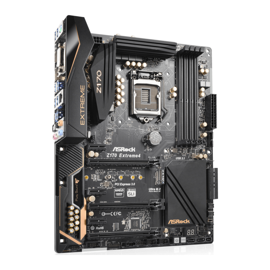
Seite 3: Motherboard-Layout
Z170 Extreme4+ / Z170 Extreme4 Motherboard Layout CPU_FAN1 ATX12V1 CPU_FAN2 CLRC BTN1 USB 3.0 T: USB3 B: USB4 USB 3.0 Top: T: USB5 RJ-45 B: USB6 USB 3.1 T: USB31_TA_1 B: USB31_TC_1 CMOS Battery CHA_FAN1 PCI Express 3.0 PCIE1 Front USB 3.0 PCIE2 CHA_FAN3 Ultra M.2... - Seite 4 No. Description ATX 12V Power Connector (ATX12V1) CPU Fan Connector (CPU_FAN2) CPU Fan Connector (CPU_FAN1) 2 x 288-pin DDR4 DIMM Slots (DDR4_A1, DDR4_B1) 2 x 288-pin DDR4 DIMM Slots (DDR4_A2, DDR4_B2) ATX Power Connector (ATXPWR1) USB 3.0 Header (USB3_7_8) Chassis Fan Connector (CHA_FAN3) SATA3 Connectors (SATA3_0_2) SATA3 Connectors (SATA3_1_3) SATA Express Connectors (SATA_EXP_0_1)
- Seite 5 Z170 Extreme4+ / Z170 Extreme4 I/O Panel No. Description No. Description PS/2 Mouse/Keyboard Port USB 3.1 Type-A Port (USB31_TA_1) DVI-D Port USB 3.1 Type-C Port (USB31_TC_1) LAN RJ-45 Port* USB 3.0 Ports (USB3_56) Central / Bass (Orange) USB 3.0 Ports (USB3_34) Rear Speaker (Black) DisplayPort 1.2 Line In (Light Blue)
- Seite 6 * here are two LEDs on each LAN port. Please refer to the table below for the LAN port LED indications. ACT/LINK LED SPEED LED LAN Port Activity / Link LED Speed LED Status Description Status Description No Link 10Mbps connection Blinking Data Activity Orange...
-
Seite 7: Front Panel
Z170 Extreme4+ / Z170 Extreme4 ASRock Front USB 3.1 Panel (for Z170 Extreme4+ / Z170 Ex- treme4+ only) Speciications • 75mm (W) x 42.8mm (H) x 148mm (L) Dimension • ASMedia ASM1142 Controller Controller • 1 x USB 3.1 Type-A Port (10 Gb/s) (Supports ESD Protection... - Seite 8 SATA Express Connector on the ASRock Front USB 3.1 Panel. Step 3 Connect one end of the USB Power Cable to the USB Power Connector on the ASRock Front USB 3.1 Panel. Step4 Install ASRock Front USB 3.1 Panel into the drive...
- Seite 9 Z170 Extreme4+ / Z170 Extreme4 Step 5 Screw ASRock Front USB 3.1 Panel to the drive bay with screws. Step 6 Connect the PSU’s SATA Power Cable to the SATA Power Connector. Step 7 Connect the other end of the SATA Express Cable to the SATA Express Connector on the motherboard.
-
Seite 10: Package Contents
ASRock’s website without further notice. If you require technical support related to this motherboard, please visit our website for speciic information about the model you are using. You may ind the latest VGA cards and CPU support list on ASRock’s website as well. ASRock website http://www.asrock.com. - Seite 11 • 4 x DDR4 DIMM Slots • Supports DDR4 3200+(OC)*/2933(OC)/2800(OC)/2400 (OC)/2133 non-ECC, un-bufered memory * Please refer to Memory Support List on ASRock's website for more information. (http://www.asrock.com/) • Max. capacity of system memory: 64GB • Supports Intel® Extreme Memory Proile (XMP) 2.0 • 15μ...
- Seite 12 • 7.1 CH HD Audio with Content Protection (Realtek Audio ALC1150 Audio Codec) • Premium Blu-ray Audio support • Supports Surge Protection (ASRock Full Spike Protection) • Supports Purity Sound - Nichicon Fine Gold Series Audio Caps - 115dB SNR DAC with Diferential Ampliier - TI®...
-
Seite 13: Rear Panel
Z170 Extreme4+ / Z170 Extreme4 • Gigabit LAN 10/100/1000 Mb/s • Giga PHY Intel® I219V • Supports Wake-On-LAN • Supports Lightning/ESD Protection (ASRock Full Spike Protection) • Supports Energy Eicient Ethernet 802.3az • Supports PXE • 1 x PS/2 Mouse/Keyboard Port Rear Panel • 1 x DVI-D Port... -
Seite 14: Hardware Monitor
• 1 x hunderbolt AIC Connector • 2 x USB 2.0 Headers (Support 4 USB 2.0 ports) (Supports ESD Protection (ASRock Full Spike Protection)) • 1 x USB 3.0 Header (Supports 2 USB 3.0 ports) (Supports ESD Protection (ASRock Full Spike Protection)) • 1 x Dr. - Seite 15 * To install Windows® 7 OS, a modiied installation disk with xHCI drivers packed into the ISO ile is required. Please refer to page 195 for more detailed instructions. * For the updated Windows® 10 driver, please visit ASRock’s website for details: http://www.asrock.com • FCC, CE, WHQL Certiica- • ErP/EuP Ready (ErP/EuP ready power supply is required)
- Seite 16 Chapter 2 Installation his is an ATX form factor motherboard. Before you install the motherboard, study the coniguration of your chassis to ensure that the motherboard its into it. Pre-installation Precautions Take note of the following precautions before you install motherboard components or change any motherboard settings.
-
Seite 17: Installing The Cpu
Z170 Extreme4+ / Z170 Extreme4 2.1 Installing the CPU 1. Before you insert the 1151-Pin CPU into the socket, please check if the PnP cap is on the socket, if the CPU surface is unclean, or if there are any bent pins in the socket. - Seite 18 English...
- Seite 19 Z170 Extreme4+ / Z170 Extreme4 Please save and replace the cover if the processor is removed. he cover must be placed if you wish to return the motherboard for ater service.
- Seite 20 2.2 Installing the CPU Fan and Heatsink...
- Seite 21 Z170 Extreme4+ / Z170 Extreme4 2.3 Installing Memory Modules (DIMM) his motherboard provides four 288-pin DDR4 (Double Data Rate 4) DIMM slots, and supports Dual Channel Memory Technology. 1. For dual channel coniguration, you always need to install identical (the same brand, speed, size and chip-type) DDR4 DIMM pairs.
- Seite 22 English...
- Seite 23 Z170 Extreme4+ / Z170 Extreme4 2.4 Expansion Slots (PCI Express Slots) here are 6 PCI Express slots on the motherboard. Before installing an expansion card, please make sure that the power supply is switched of or the power cord is unplugged. Please read the documentation of the expansion card and make necessary hardware settings for the card before you start the installation.
- Seite 24 2.5 Jumpers Setup he illustration shows how jumpers are setup. When the jumper cap is placed on the pins, the jumper is “Short”. If no jumper cap is placed on the pins, the jumper is “Open”. he illustration shows a 3-pin jumper whose pin1 and pin2 are “Short” when a jumper cap is placed on these 2 pins.
- Seite 25 Z170 Extreme4+ / Z170 Extreme4 BIOS Selection Jumper (BIOS_SEL1) Default Backup BIOS (see p.1, No. 12) (Main BIOS) his motherboard has two BIOS onboard, a main BIOS (BIOS_A) and a backup BIOS (BIOS_B), which enhances protection for the safety and stability of your system.
- Seite 26 2.6 Onboard Headers and Connectors Onboard headers and connectors are NOT jumpers. Do NOT place jumper caps over these headers and connectors. Placing jumper caps over the headers and connectors will cause permanent damage to the motherboard. System Panel Header Connect the power PLED+ PLED-...
- Seite 27 Z170 Extreme4+ / Z170 Extreme4 Power LED and Speaker Please connect the SPEAKER DUMMY Header chassis power LED and DUMMY (7-pin SPK_PLED1) the chassis speaker to this (see p.1, No. 14) header. PLED+ PLED+ PLED- Serial ATA3 Connectors hese six SATA3 (SATA3_0_2: connectors support SATA see p.1, No.
- Seite 28 USB 3.0 Header Besides six USB 3.0 ports Vbus Vbus Vbus IntA_PB_SSRX- (19-pin USB3_7_8) on the I/O panel, there IntA_PA_SSRX- IntA_PB_SSRX+ IntA_PA_SSRX+ (see p.1, No. 7) is one header on this IntA_PB_SSTX- IntA_PA_SSTX- IntA_PB_SSTX+ motherboard. Each USB IntA_PA_SSTX+ IntA_PB_D- 3.0 header can support IntA_PA_D- IntA_PB_D+ IntA_PA_D+...
- Seite 29 Z170 Extreme4+ / Z170 Extreme4 CPU Fan Connectors his motherboard pro- FAN_SPEED FAN_VOLTAGE_CONTROL (4-pin CPU_FAN1) FAN_SPEED_CONTROL vides a 4-Pin CPU fan (see p.1, No. 3) (Quiet Fan) connector. (4-pin CPU_FAN2) If you plan to connect a (see p.1, No. 2) 3-Pin CPU fan, please connect it to Pin 1-3.
- Seite 30 TPM Header his connector supports Trusted (17-pin TPMS1) Platform Module (TPM) system, (see p.1, No. 23) which can securely store keys, digital certiicates, passwords, and data. A TPM system also helps enhance network security, protects digital identities, and ensures platform integrity.
-
Seite 31: Smart Switches
Z170 Extreme4+ / Z170 Extreme4 2.7 Smart Switches he motherboard has three smart switches: Power Switch, Reset Switch and Clear CMOS Switch, allowing users to quickly turn on/of the system, reset the system or clear the CMOS values. Power Switch Power Switch allows users (PWRBTN) to quickly turn on/of the... - Seite 32 2.8 Dr. Debug Dr. Debug is used to provide code information, which makes troubleshooting even easier. Please see the diagrams below for reading the Dr. Debug codes. Code Description Please check if the CPU is installed correctly and then clear CMOS.
- Seite 33 Z170 Extreme4+ / Z170 Extreme4 Problem related to USB devices. Please try removing all USB devices. Problem related to memory. Please re-install the CPU and memory then clear CMOS. If the problem still exists, please install only one memory module or try using other memory modules.
- Seite 34 2.9 M.2_SSD (NGFF) Module Installation Guide The M.2, also known as the Next Generation Form Factor (NGFF), is a small size and versatile card edge connector that aims to replace mPCIe and mSATA. The Ultra M.2 Socket (M2_1) supports M.2 PCI Express module up to Gen3 x4 (32 Gb/s). Please be noted that the Ultra M.2 Socket (M2_1) is shared with the SATA3_0, SATA3_1 and the SATA Express connector (SATA_EXP0).
- Seite 35 Z170 Extreme4+ / Z170 Extreme4 Step 3 Move the standof based on the module type and length. he standof is placed at the nut location D by default. Skip Step 3 and 4 and go straight to Step 5 if you are going to use the default nut.
- Seite 36 SATA3 2280 TM8PS4256GMC105 Team 256GB SATA3 2242 TM4PS4256GMC105 Transcend 256GB SATA3 2242 TS256GMTS400 Transcend 512GB SATA3 2280 TS512GMTS800 Transcend 512GB SATA3 2260 TS512GMTS600 For the latest updates of M.2_SSD (NFGG) module support list, please visit our website for details: http://www.asrock.com...
-
Seite 37: Einleitung
Z170 Extreme4+ / Z170 Extreme4 1 Einleitung Vielen Dank, dass Sie sich für das Z170 Extreme4+ / Z170 Extreme4 von ASRock entschieden haben – ein zuverlässiges Motherboard, das konsequent unter der strengen Qualitätskontrolle von ASRock hergestellt wurde. Es liefert ausgezeichnete Leistung mit robustem Design, das ASRocks Streben nach Qualität und Beständigkeit... -
Seite 38: Technische Daten
Celeron® der 6. Generation (Sockel 1151) • Digipower-Design • 10-Leistungsphasendesign • Unterstützt Intel® Turbo Boost 2.0-Technologie • Unterstützt CPUs mit freiem Multiplikator der Intel® K-Serie • Unterstützt ASRock BCLK-Übertaktung (voller Bereich) • Unterstützt ASRock-Hyper-BCLK-Engine • Intel ® Chipsatz Z170 • Dualkanal-DDR4-Speichertechnologie... - Seite 39 DVI-D-, HDMI- und DisplayPort 1.2-Ports • 7.1-Kanal-HD-Audio mit Inhaltsschutz (Realtek ALC1150- Audio Audiocodec) • Erstklassige Blu-ray-Audiounterstützung • Unterstützt Überspannungsschutz (ASRock Full Spike Protection) • Unterstützt Purity Sound - Nichicon-Audiokappen der Fine Gold-Serie - 115-dB-SRV-DAC mit Diferentialverstärker - TI® NE5532 – erstklassiger Headset-Verstärker (unterstützt...
- Seite 40 • 1 x DisplayPort 1.2 • 1 x Optischer SPDIF-Ausgang • 1 x USB 3.1-Typ-A-Port (10 Gb/s) (ASMedia ASM1142) (unterstützt Schutz gegen elektrostatische Entladung (ASRock Full Spike Protection)) • 1 x USB 3.1-Typ-C-Port (10 Gb/s) (ASMedia ASM1142) (unterstützt Schutz gegen elektrostatische Entladung (ASRock Full Spike Protection)) • 6 x USB 3.0-Ports (Intel®...
-
Seite 41: Anschluss
• 1 x Audioanschluss an Frontblende • 1 x hunderbolt-Erweiterungskartenanschluss • 2 x USB 2.0-Stitleisten (unterstützen 4 USB 2.0-Ports) (unter- stützt Schutz gegen elektrostatische Entladung (ASRock Full Spike Protection)) • 1 x USB 3.0-Stitleiste (unterstützt 2 USB 3.0-Ports) (unter- stützt Schutz gegen elektrostatische Entladung (ASRock Full Spike Protection)) • 1 x Dr. -
Seite 42: Betrieb
• ErP/EuP ready (ErP/EuP ready-Netzteil erforderlich) zierungen * Detaillierte Produktinformationen inden Sie auf unserer Webseite: http://www.asrock.com Bitte beachten Sie, dass mit einer Übertaktung, zu der die Anpassung von BIOS-Einstellungen, die Anwendung der Untied Overclocking Technology oder die Nutzung von Übertaktung- swerkzeugen von Drittanbietern zählen, bestimmte Risiken verbunden sind. -
Seite 43: Jumpereinstellung
Z170 Extreme4+ / Z170 Extreme4 1.3 Jumpereinstellung Die Abbildung zeigt, wie die Jumper eingestellt werden. Wenn die Jumper-Kappe auf den Kontakten angebracht ist, ist der Jumper „kurzgeschlossen“. Wenn keine Jumper- Kappe auf den Kontakten angebracht ist, ist der Jumper „ofen“. Die Abbildung zeigt einen 3-poligen Jumper, dessen Kontakt 1 und Kontakt 2 „kurzgeschlossen“... - Seite 44 BIOS-Auswahl-Jumper (BIOS_SEL1) Standard Ausfall-BIOS (siehe S. 1, Nr. 12) (Haupt-BIOS) Dieses Motherboard verfügt über zwei integrierte BIOS, ein Haupt-BIOS (BIOS_A) und ein Ausfall-BIOS (BIOS_B), die den Schutz in puncto Sicherheit und Stabilität Ihres Systems steigern. Normalerweise läut das System über das Haupt-BIOS. Falls das Haupt-BIOS jedoch defekt oder beschädigt ist, schließen Sie bitte Kontakt 2 und Kontakt 3 über eine Jumperkappe kurz;...
-
Seite 45: Integrierte Stiftleisten Und Anschlüsse
Z170 Extreme4+ / Z170 Extreme4 1.4 Integrierte Stiftleisten und Anschlüsse Integrierte Stitleisten und Anschlüsse sind KEINE Jumper. Bringen Sie KEINE Jumper-Kappen an diesen Stitleisten und Anschlüssen an. Durch Anbringen von Jumper-Kappen an diesen Stitleisten und Anschlüssen können Sie das Motherboard dauerhat beschädigen. Systemblende-Stitleiste Verbinden Sie PLED+... - Seite 46 Betrieb-LED- und Bitte verbinden Sie SPEAKER DUMMY Lautsprecher-Stitleiste die Betrieb-LED des DUMMY (7-polig, SPK_PLED1) Gehäuses und den (siehe S. 1, Nr. 14) Gehäuselautsprecher mit dieser Stitleiste. PLED+ PLED+ PLED- Serial-ATA-III-Anschlüsse Diese sechs SATA-III- (SATA3_0_2: Anschlüsse unterstützen siehe S. 1, Nr. 9) SATA-Datenkabel für (SATA3_1_3: interne Speichergeräte mit...
- Seite 47 Z170 Extreme4+ / Z170 Extreme4 USB 3,0-Stitleiste Neben sechs USB 3.0-Ports Vbus Vbus Vbus IntA_PB_SSRX- (19-polig, USB3_7_8) an der E/A-Blende beindet IntA_PA_SSRX- IntA_PB_SSRX+ IntA_PA_SSRX+ (siehe S. 1, Nr. 7) sich eine Stitleiste an IntA_PB_SSTX- IntA_PA_SSTX- IntA_PB_SSTX+ diesem Motherboard. Jede IntA_PA_SSTX+ IntA_PB_D- USB 3.0-Stitleiste kann IntA_PA_D-...
- Seite 48 CPU-Lüteranschlüsse Dieses Motherboard bietet FAN_SPEED FAN_VOLTAGE_CONTROL (4-polig, CPU_FAN1) FAN_SPEED_CONTROL einen 4-poligen CPU- (siehe S. 1, Nr. 3) Lüteranschluss (lautloser (4-polig, CPU_FAN2) Lüter). Falls Sie einen (siehe S. 1, Nr. 2) 3-poligen CPU-Lüter anschließen möchten, verbinden Sie ihn bitte mit Kontakt 1 bis 3. ATX-Netzanschluss Dieses Motherboard (24-polig, ATXPWR1)
- Seite 49 Z170 Extreme4+ / Z170 Extreme4 TPM-Stitleiste Dieser Anschluss unterstützt das (17-polig, TPMS1) Trusted Platform Module- (TPM) (siehe S. 1, Nr. 23) System, das Schlüssel, digitale Zertiikate, Kennwörter und Daten sicher aubewahren kann. Ein TPM-System hilt zudem bei der Stärkung der Netzwerksicher- heit, schützt digitale Identitäten und gewährleistet die Plattform- integrität.
- Seite 50 1.5 Intelligente Schalter Das Motherboard hat drei intelligente Schalter: Ein-/Ausschalter, Reset-Schalter und CMOS-löschen-Schalter, wodurch Benutzer das System schnell ein-/abschalten, zurücksetzen bzw. die CMOS-Werte löschen können. Ein-/Ausschalter Mit dem Ein-/Ausschalter (PWRBTN) kann der Benutzer das (siehe S. 1, Nr. 18) System schnell ein-/ abschalten.
-
Seite 51: Contenu De L'emballage
à modiication sans préavis. En cas de modiications du présent document, la version mise à jour sera disponible sur le site Internet ASRock sans notiication préalable. Si vous avez besoin d’une assistance technique pour votre carte mère, veuillez visiter notre site Internet pour plus de détails sur le modèle que vous utilisez. - Seite 52 • Prend en charge la technologie Intel® Turbo Boost 2.0 • Prend en charge les processeurs débloqués de la série K Intel® • Prend en charge l’ o verclocking ASRock BCLK Full-range • Prend en charge le moteur ASRock Hyper BCLK • Intel...
- Seite 53 Audio Realtek ALC1150) • Compatible audio Blu-ray Premium • Protection contre les surtensions (Protection complète contre les pics ASRock) • Prend en charge Purity Sound - Couvercles audio série en or in Nichicon - 115dB SNR DAC avec ampliicateur diférentiel - Ampliicateur de casque TI®...
- Seite 54 • Giga PHY Intel® I219V • Prend en charge la fonction Wake-On-LAN • Protection contre les orages/décharges électrostatiques (Protection complète contre les pics ASRock) • Prend en charge la fonction d’ é conomie d’ é nergie Ethernet 802.3az • Prend en charge PXE • 1 x port souris/clavier PS/2...
- Seite 55 • 1 x socket Ultra M.2, prend en charge les modules M.2 SATA3 6,0 Gb/s et M.2 PCI Express jusqu’à Gen3 x4 (32 Gb/s) * Prend en charge le kit ASRock U.2 • 1 x embase pour port COM Connecteur • 1 x embase TPM...
- Seite 56 • ErP/EuP Ready (alimentation ErP/EuP ready requise) tions * pour des informations détaillées de nos produits, veuillez visiter notre site : http://www.asrock.com Il est important de signaler que l’ o vercloking présente certains risques, incluant des modiica- tions du BIOS, l’ a pplication d’une technologie d’ o verclocking déliée et l’utilisation d’ o utils d’...
- Seite 57 Z170 Extreme4+ / Z170 Extreme4 1.3 Coniguration des cavaliers (jumpers) L’illustration ci-dessous vous renseigne sur la coniguration des cavaliers (jumpers). Lorsque le capuchon du cavalier est installé sur les broches, le cavalier est « court- circuité ». Si le capuchon du cavalier n’ e st pas installé sur les broches, le cavalier est « ouvert ».
- Seite 58 Sélection du cavalier du BIOS Par défaut BIOS de (BIOS_SEL1) (BIOS principal) secours (voir p.1, No. 12) Cette carte mère est dotée de deux BIOS – un BIOS principal (BIOS_A), et un BIOS de secours (BIOS_B) – ce qui permet d’ o ptimiser la protection du système pour des performances iables et stables.
- Seite 59 Z170 Extreme4+ / Z170 Extreme4 1.4 Embases et connecteurs de la carte mère Les embases et connecteurs situés sur la carte NE SONT PAS des cavaliers. Ne placez JAMAIS de capuchons de cavaliers sur ces embases ou connecteurs. Placer un capuchon de cavalier sur ces embases ou connecteurs endommagera irrémédiablement votre carte mère.
- Seite 60 Prise DEL d’alimentation Veuillez brancher la DEL SPEAKER DUMMY et haut-parleur d'alimentation du châs- DUMMY (SPK_PLED1 à 7 broches) sis et le haut-parleur du (voir p.1, No. 14) châssis sur ce connecteur. PLED+ PLED+ PLED- Connecteurs Serial ATA3 Ces six connecteurs (SATA3_0_2: SATA3 sont compatibles (voir p.1, No.
- Seite 61 Z170 Extreme4+ / Z170 Extreme4 Embases USB 3.0 En plus des six ports Vbus Vbus (USB3_7_8 19 broches) USB 3.0 sur le panneau Vbus IntA_PB_SSRX- IntA_PA_SSRX- IntA_PB_SSRX+ (voir p.1, No. 7) E/S, cette carte mère IntA_PA_SSRX+ IntA_PB_SSTX- est dotée d’une embase IntA_PA_SSTX- IntA_PB_SSTX+ IntA_PA_SSTX+...
- Seite 62 Connecteurs du Cette carte mère est FAN_SPEED FAN_VOLTAGE_CONTROL ventilateur du processeur FAN_SPEED_CONTROL dotée d’un connecteur (CPU_FAN1 à 4 broches) pour ventilateur de (voir p.1, No. 3) processeur (Quiet Fan) (CPU_FAN2 à 4 broches) à 4 broches. Si vous en- (voir p.1, No. 2) visagez de connecter un ventilateur de processeur à...
- Seite 63 Z170 Extreme4+ / Z170 Extreme4 Embase pour port série Cette embase COM1 RRXD1 DDTR#1 (COM1 à 9 broches) prend en charge un DDSR#1 CCTS#1 (voir p.1, No. 24) module de port série. RRI#1 RRTS#1 TTXD1 DDCD#1 Embase TPM Ce connecteur prend en charge (TPMS1 à...
- Seite 64 1.5 Boutons intelligents La carte mère est équipée de trois boutons intelligents : bouton de mise en marche, bouton de réinitialisation et bouton d’ e facement CMOS qui permettent aux utilisateurs d’allumer/éteindre le système, de réinitialiser le système ou d’ e facer les valeurs CMOS en toute simplicité.
-
Seite 65: Contenuto Della Confezione
Web di ASRock senza ulteriore preavviso. Per il supporto tecnico correlato a questa scheda madre, visitare il nostro sito Web per informazioni speciiche relative al modello attualmente in uso. -
Seite 66: Speciiche
• Potenza a 10 fasi • Supporta la tecnologia Intel® Turbo Boost 2.0 • Supporto di CPU unlocked Intel® K-Series • Supporta gamma completa overclocking BCLK ASRock • Compatibile con il motore ASRock Hyper BCLK • Intel ® Chipset Z170 • Tecnologia memoria DDR4 Dual Channel... - Seite 67 Audio Realtek ALC1150) • Supporto audio Blu-ray Premium • Supporto protezione da sovratensione (protezione completa ASRock dai picchi di corrente) • Supporto di Purity Sound - Cappucci audio Nichicon serie Fine Gold - 115dB SNR DAC con ampliicatore diferenziale - TI® NE5532 Premium Headset Ampliier (supporta cuie...
- Seite 68 • LAN Gigabit 10/100/1000 Mb/s • Giga PHY Intel® I219V • Supporta Wake-On-LAN • Supporto la protezione da fulmini/scariche elettrostatiche (ESD) (protezione completa ASRock dai picchi di corrente) • Supporta Energy Eicient Ethernet 802.3az • Supporta PXE • 1 x porta mouse/tastiera PS/2 I/O pan- • 1 x porta DVI-D...
-
Seite 69: Hardware Monitor
• 2 x Collettori USB 2.0 (supporto di 4 porte 4 USB 2.0) (sup- porto protezione da scariche elettrostatiche (ESD) (protezione completa ASRock dai picchi di corrente)) • 1 x Collettore USB 3.0 (supporta 2 porte USB 3.0) (supporto protezione da scariche elettrostatiche (ESD) (protezione com- pleta ASRock dai picchi di corrente)) • 1 x Dr. - Seite 70 * Per installare Windows® 7, è necessario un disco di installazione modiicato con i driver xHCI integrati nel ile ISO. Fare riferi- mento a pagina 195 per altre istruzioni dettagliate. * Per il driver aggiornato di Windows® 10, visitare il sito ASRock all’indirizzo:http://www.asrock.com • FCC, CE, WHQL Certii- • ErP/EuP Ready (è...
- Seite 71 Z170 Extreme4+ / Z170 Extreme4 1.3 Impostazione jumper L'illustrazione mostra in che modo vengono impostati i jumper. Quando il cappuccio del jumper è posizionato sui pin, il jumper è "cortocircuitato". Se sui pin non è posizionato alcun cappuccio del jumper, il jumper è "aperto". L'illustrazione mostra un jumper a 3 pin i cui pin1 e pin2 sono "cortocircuitati"...
- Seite 72 Jumper di selezione BIOS (BIOS_SEL1) predeinito BIOS di (vedere pag. 1, n. 12) (Main BIOS) backup Questa scheda madre è dotata di due BIOS, un BIOS principale (BIOS_A) e un BIOS di backup (BIOS_B), che migliorano la protezione, la sicurezza e la stabilità del sistema.
- Seite 73 Z170 Extreme4+ / Z170 Extreme4 1.4 Header e connettori sulla scheda Gli header e i connettori sulla scheda NON sono jumper. NON posizionare cappucci del jumper su questi header e connettori. Il posizionamento di cappucci del jumper su header e connettori provocherà...
- Seite 74 Connettore LED Collegare i LED alimen- SPEAKER DUMMY alimentazione e tazione e l’altoparlante a DUMMY altoparlante questo connettore. (SPK_PLED1 7 pin) (vedere pag. 1, n. 14) PLED+ PLED+ PLED- Connettori Serial ATA3 Questi sei connettori (SATA3_0_2: SATA3 supportano cavi di vedere pag.
- Seite 75 Z170 Extreme4+ / Z170 Extreme4 Header USB 3.0 Oltre alle sei porte USB 3.0 Vbus Vbus Vbus IntA_PB_SSRX- (USB3_7_8 19 pin) del pannello I/O, questa IntA_PB_SSRX+ IntA_PA_SSRX- IntA_PA_SSRX+ (vedere pag. 1, n. 7) scheda madre è dotata IntA_PB_SSTX- IntA_PA_SSTX- IntA_PB_SSTX+ di un collettore.
- Seite 76 Connettori della ventola Questa scheda madre è FAN_SPEED FAN_VOLTAGE_CONTROL FAN_SPEED_CONTROL della CPU dotata di un connettore per (CPU_FAN1 a 4 pin) la ventola della CPU (Ven- (vedere pag. 1, n. 3) tola silenziosa) a 4 pin. Se (CPU_FAN2 a 4 pin) si decide di collegare una (vedere pag.
- Seite 77 Z170 Extreme4+ / Z170 Extreme4 Header TPM Questo connettore supporta il (TPMS1 a 17 pin) sistema Trusted Platform Module (vedere pag. 1, n. 23) (TPM), che può archiviare in modo sicuro chiavi, certii- cati digitali, password e dati. Un sistema TPM permette anche di potenziare la sicurezza della rete, di proteggere identità...
- Seite 78 1.5 Interruttori intuitivi La scheda madre è dotata di tre interruttori intuitivi: Interruttore d’alimentazione, interruttore di ripristino ed interruttore Clear CMOS, che consentono di accendere/ spegnere rapidamente il sistema, ripristinare il sistema o cancellare i valori CMOS. Interruttore L’interruttore d’alimentazione d’alimentazione consente (PWRBTN) di accendere/spegnere...
-
Seite 79: Contenido Del Paquete
Si esta documentación sufre alguna modiicación, la versión actualizada estará disponible en el sitio web de ASRock sin previo aviso. Si necesita asistencia técnica relacionada con esta placa base, visite nuestro sitio web para obtener información especíica sobre el modelo que esté... - Seite 80 2800(OC)/2400(OC)/2133 no ECC. * Para obtener más información, consulte la lista de memorias compatibles en el sitio web de ASRock. (http://www.asrock.com/) • Capacidad máxima de la memoria del sistema: 64GB • Admite Peril de memoria extremo de Intel® (XMP) 2.0 • Contacto 15μ...
- Seite 81 ALC1150 Audio Codec) • Compatible con audio Blu-ray Premium • Compatible con protección por sobretensión (protección ASRock Full Spike) • Compatible con Purity Sound - Tapas de audio Nichion de la serie Fine Gold - 115dB SNR DAC con ampliicador diferencial - Ampliicador de auriculares de alta calidad TI®...
- Seite 82 Si cualquiera de ellos está en uso, los otros se deshabilitan. • 1 x Zócalo Ultra M.2, que admite el módulo SATA3 6.0 Gb/s M.2 y el módulo PCI Express M.2 hasta Gen3 x4 (32 Gb/s) * Admiteel Kit U.2 de ASRock...
- Seite 83 • 2 cabezales USB 2.0 (compatible con 4 puertos USB 2.0) (com- patible con protección contra electricidad estática (protección ASRock Full Spike)) • 1 cabezal USB 3.0 (compatible con 2 puertos USB 3.0) (com- patible con protección contra electricidad estática (protección ASRock Full Spike)) • 1 Dr.
- Seite 84 ISO. Consulte la página 195 para obtener información más detallada. * Para obtener el controlador actualizado para Windows® 10, visite el sitio Web desde ASRock para obtener detalles: http://www.asrock.com • FCC, CE, WHQL Certiica- • Compatible con ErP/EuP (requiere toma de alimentación...
- Seite 85 Z170 Extreme4+ / Z170 Extreme4 1.3 Instalación de los puentes La instalación muestra cómo deben instalarse los puentes. Cuando la tapa de puente se coloca en los pines, el puente queda “Corto”. Si no coloca la tapa de puente en los pines, el puente queda “Abierto”.
- Seite 86 Puente de selección del BIOS Predeterminado BIOS de copia (BIOS_SEL1) (BIOS Principal) de seguridad (consulte la pág.1, N.º 12) Esta placa base contiene dos BIOS integrados, un BIOS principal (BIOS_A) y un BIOS de copia de seguridad (BIOS_B), que aumentan la protección para la seguridad y la estabilidad de su sistema.
- Seite 87 Z170 Extreme4+ / Z170 Extreme4 1.4 Conectores y cabezales incorporados Los cabezales y conectores incorporados NO son puentes. NO coloque tapas de puente sobre estos cabezales y conectores. Si coloca tapas de puente sobre los cabezales y conectores dañará de forma permanente la placa base. Cabezal del panel del Conecte el interruptor de PLED+...
- Seite 88 LED de alimentación y Conecte el LED de ali- SPEAKER DUMMY base de conexiones para la mentación del chasis y el DUMMY altavoz altavoz del chasis a esta (SPK_PLED1 de 7 base de conexiones. contactos) PLED+ (consulte la pág.1, N.º 14) PLED+ PLED- Conectores Serie ATA3...
- Seite 89 Z170 Extreme4+ / Z170 Extreme4 Cabezal USB 3.0 Además de seis puertos Vbus Vbus Vbus IntA_PB_SSRX- (USB3_7_8 de 19 USB 3.0 en el panel I/O, IntA_PB_SSRX+ IntA_PA_SSRX- IntA_PA_SSRX+ contactos) esta placa base contiene un IntA_PB_SSTX- IntA_PA_SSTX- IntA_PB_SSTX+ (consulte la pág.1, N.º 7) cabezal.
- Seite 90 Conectores del ventilador Esta placa base contiene FAN_SPEED FAN_VOLTAGE_CONTROL FAN_SPEED_CONTROL de la CPU un conector de ventilador (CPU_FAN1 de 4 pines) (ventilador silencioso) de (consulte la pág.1, N.º 3) CPU de 4 pines. Si tiene (CPU_FAN2 de 4 pines) pensando conectar un ven- (consulte la pág.1, N.º...
- Seite 91 Z170 Extreme4+ / Z170 Extreme4 Cabezal TPM Este conector es compatible con el (TPMS1 de 17 pines) sistema Módulo de Plataforma Se- (consulte la pág.1, N.º 23) gura (TPM, en inglés), que puede almacenar de forma segura claves, certiicados digitales, contraseñas y datos.
- Seite 92 1.5 Interruptores inteligentes La placa base contiene tres interruptores inteligentes: Interruptor de alimentación, interruptor de reseteo e interruptor de borrado de CMOS; que permiten a los usuarios encender y apagar rápidamente el sistema, resetearlo o borrar los valores de CMOS. Interruptor de El interruptor de alimentación...
-
Seite 93: Комплект Поставки
• 1 x карта ASRock SLI_Bridge_2S • 1 x Винт для гнезда M.2 • Фронтальная панель USB 3.1 ASRock – 1 шт. (только для Z170 Extreme4+) • Винты для фронтальной панели USB 3.1 – 4 шт. (только для Z170 Extreme4+) • Кабель... - Seite 94 • Digi Power design • Система питания 10 • Поддержка технологии Intel® Turbo Boost 2.0 • Поддержка процессоров Intel® серии K с разблокированным множителем • Поддержка полного разгона процессора ASRock BCLK • Поддерживает систему ASRock Hyper BCLK • Intel ® Чипсет...
- Seite 95 Blu-ray (BD) через порты DVI-D, HDMI и DisplayPort 1.2 • 7.1-канальный звук высокой четкости HD Audio с Аудио защитой данных (аудиокодек Realtek ALC1150) • Поддержка Premium Blu-ray Audio • Защита от перенапряжения (ASRock Full Spike Protection) • Поддержка Purity Sound - Конденсаторы для аудиосистем серии Nichicon Fine Gold - 115 дБ...
- Seite 96 • Gigabit LAN 10/100/1000 Мб/с • Giga PHY Intel® I219V • Поддержка Wake-On-LAN • Молниезащита и защита электростатического напряжения (ASRock Full Spike Protection) • Поддержка Energy Eicient Ethernet 802.3az • Поддержка PXE • 1 x PS/2 для мыши/клавиатуры Порты ввода- • 1 x DVI-D...
- Seite 97 • 1 x Ultra M.2 Socket, поддержка модуля M.2 SATA3 со скоростью обмена данными 6,0 ГБ/с и модуля M.2 PCI Express до версии Gen3 x4 (32 ГБ/с) * Поддержка комплекта ASRock U.2 • 1 x колодка СОМ-порта Разъемы • 1 x Колодка ТРМ...
- Seite 98 измененный установочный диск с драйверами xHCI, упакованными в файл ISO. Подробные инструкции представлены на стр. 195. * Подробные сведения об обновлении драйвера Win- dows® 10 представлены на веб-сайте ASRock:http://www. asrock.com • FCC, CE, WHQL Сертификация • Совместимость с ErP/EuP (необходим блок питания, соответствующий...
- Seite 99 Z170 Extreme4+ / Z170 Extreme4 1.3 Установка перемычек Установка перемычек показана на рисунке. При установке колпачковой перемычки на контакты перемычка «замкнута». Если колпачковая перемычка на контакты не установлена, перемычка «разомкнута». На рисунке показана 3-контактная перемычка с замкнутыми контактами 1 и 2 при установке на них колпачковой...
- Seite 100 Перемычка выбора BIOS (BIOS_SEL1) по умолчанию Резервная (См. стр. 1, № 12) (основная BIOS) BIOS Эта материнская плата снабжена двумя BIOS — основной BIOS (BIOS_A) и BIOS резервного копирования (BIOS_B), — что повышает уровень защиты и стабильности работы системы. Обычно система использует основную BIOS. При...
- Seite 101 Z170 Extreme4+ / Z170 Extreme4 1.4 Колодки и разъемы, расположенные на материнской плате Расположенные на материнской плате колодки и разъемы перемычками НЕ являются. НЕ устанавливайте на эти колодки и разъемы колпачковые перемычки. Установка колпачковых перемычек на эти колодки и разъемы может вызвать неустранимое повреждение...
- Seite 102 Колодка светодиодного Предназначена SPEAKER индикатора питания и для подключения DUMMY DUMMY динамика корпуса светодиодного (7-контактная, SPK_ индикатора питания и PLED1) динамика корпуса. (См. стр. 1, № 14) PLED+ PLED+ PLED- Разъемы Serial ATA3 Эти шесть шесть SATA3 (SATA3_0_2: предназначены для См.
- Seite 103 Z170 Extreme4+ / Z170 Extreme4 Колодки USB 2.0 На системной плате USB_PWR (9-контактная, USB_1_2) размещены две (См. стр. 1, № 21) колодки. Каждая DUMMY (9-контактная USB_3_4) колодка USB 2.0 может (См. стр. 1, № 20) поддерживать два порта. USB_PWR Колодка USB 3.0 Кроме...
- Seite 104 Разъемы вентиляторов Предназначены для FAN_VOLTAGE корпуса подключения кабелей CHA_FAN_SPEED (4-контактный, CHA_ FAN_SPEED_CONTROL разъемов вентиляторов FAN1) и подключения черного (См. стр. 1, № 26) провода к заземлению. FAN_SPEED_CONTROL CHA_FAN_SPEED (4-контактный, CHA_ FAN_VOLTAGE FAN2) (См. стр. 1, № 13) FAN_VOLTAGE CHA_FAN_SPEED FAN_SPEED_CONTROL (4-контактный, CHA_ FAN3) (См.
- Seite 105 Z170 Extreme4+ / Z170 Extreme4 Разъем питания АТХ 12 В Эта материнская плата (8-контактный, снабжена 8-контактным ATX12V1) разъемом питания АТХ (См. стр. 1, № 1) 12 В. Чтобы использовать 4-контактный разъем питания ATX, подключите его вдоль контакта 1 и контакта 5. Разъем...
- Seite 106 1.5 Электронные кнопки Материнская плата снабжена тремя электронными кнопками: кнопка питания, кнопка перезагрузки и переключатель сброса настроек CMOS, предназначенными для быстрого включения/выключения системы, перезагрузки системы и обнуления значений CMOS. Кнопка питания Кнопка питания (PWRBTN) предназначена для (См. стр. 1, № 18) быстрого...
-
Seite 107: Conteúdo Da Embalagem
Se precisar de assistência técnica relacionada a esta placa principal, visite o nosso site para obter informações especíicas sobre o modelo que estiver utilizando. Você também poderá encontrar a lista de placas VGA e CPU mais recentes suportadas no site da ASRock. Site da ASRock http://www.asrock.com. - Seite 108 • Design Digi Power • Design com 10 fases de alimentação • Suporta a tecnologia Intel® Turbo Boost 2.0 • Suporta CPU desbloqueado da série K da Intel® • Suporta Overclocking total ASRock BCLK • Motor ASRock Hyper BCLK • Intel ®...
- Seite 109 Áudio áudio Realtek ALC1150) • Suporte áudio Blu-ray superior • Suporta proteção contra sobretensão (Proteção Total Contra Picos ASRock) • Suporta Purity Sound - Capacitor de Áudio Série Ouro Fino Nichicon - 115dB SNR DAC com ampliicador diferencial - Ampliicador de Fone de Ouvido TI®NE5532 Premium (suporta fones de ouvido de até...
- Seite 110 • 1 x Porta de saída SPDIF ótica • 1 x Porta USB 3.1 Tipo A (10 Gb/s) (ASMedia ASM1142) (Suporta Proteção ESD (Proteção Total Contra Picos ASRock)) • 1 x Porta USB 3.1 Tipo C (10 Gb/s) (ASMedia ASM1142) (Suporta Proteção ESD (Proteção Total Contra Picos ASRock))
- Seite 111 • 1 x Conector hunderbolt AIC • 2 x Plataformas USB 2.0 (Suporta 4 portas USB 2.0) (Suporta Proteção ESD (Proteção Total Contra Picos ASRock)) • 1 x Plataforma USB 3.0 (Suporta 2 portas USB 3.0) (Suporta Proteção ESD (Proteção Total Contra Picos ASRock)) • 1 Dr.
- Seite 112 ErP/EuP) * Para obter informações detalhadas sobre o produto, por favor, visite o nosso site: http://www.asrock.com Por favor, observe que existe um certo risco envolvendo overclocking, incluindo o ajuste das deinições na BIOS, a aplicação de tecnologia Untied Overclocking ou a utilização de ferra- mentas de overclocking de terceiros.
- Seite 113 Z170 Extreme4+ / Z170 Extreme4 1.3 Coniguração dos jumpers A imagem abaixo mostra como os jumpers são conigurados. Quando a tampa do jumper é colocada nos pinos, o jumper é "Curto". Se não for colocada uma tampa de jumper nos pinos, o jumper é "Aberto". A imagem mostra um jumper de 3 pinos cujos pino1 e pino2 estão "Curtos"...
- Seite 114 Jumper de seleção da BIOS (BIOS_SEL1) Padrão Fazer o backup (ver p.1, N.º 12) (BIOS principal) de BIOS Esta placa-mãe possui duas BIOS integradas, uma BIOS principal (BIOS_A) e uma BIOS de reserva (BIOS_B), que aumenta a proteção, segurança e estabilidade do seu sistema.
- Seite 115 Z170 Extreme4+ / Z170 Extreme4 1.4 Suportes e conectores onboard Os conectores e suportes onboard NÃO são jumpers. NÃO coloque tampas de jumpers sobre estes terminais e conectores Colocar tampas de jumpers sobre os terminais e conectores irá causar danos permanentes à placa-mãe. Suporte do painel de Ligue o botão de PLED+...
- Seite 116 LED de alimentação e Conecte o LED de SPEAKER DUMMY Cabeçote de Autofalante alimentação do chassi e o DUMMY (SPK_PLED1 7 pinos) autofalante do chassi a este (ver p.1, N.º 14) cabeçote. PLED+ PLED+ PLED- Conectores série ATA3 Estes seis conectores (SATA3_0_2: SATA3 suportam ver p.1, N.º...
- Seite 117 Z170 Extreme4+ / Z170 Extreme4 Suporte USB 3.0 Além de seis portas USB Vbus Vbus Vbus IntA_PB_SSRX- (USB3_7_8 19 pinos) 3.0 no painel E/S, existe IntA_PA_SSRX- IntA_PB_SSRX+ IntA_PA_SSRX+ (ver p.1, N.º 7) uma plataforma nesta IntA_PB_SSTX- IntA_PA_SSTX- IntA_PB_SSTX+ placa-mãe. Cada suporte IntA_PA_SSTX+ IntA_PB_D- USB 3.0 pode suportar...
- Seite 118 Conectores da Ventoinha Por favor, conecte os FAN_VOLTAGE do Chassi cabos do ventilador aos CHA_FAN_SPEED FAN_SPEED_CONTROL (CHA_FAN1 de 4 pinos) conectores do ventilador e (ver p.1, N.º 26) corresponda o io preto no pino terra. (CHA_FAN2 4 pinos) FAN_SPEED_CONTROL CHA_FAN_SPEED (ver p.1, N.º...
- Seite 119 Z170 Extreme4+ / Z170 Extreme4 Conector hunderbolt Por favor, conecte uma placa adicional hunderbolt™ (AIC) (5-pinos TB1) a este conector através do cabo (ver p.1, N.º 22) GPIO. Suporte da porta serial Este suporte COM1 recebe RRXD1 DDTR#1 DDSR#1 (COM1 de 9 pinos) um módulo da porta serial.
- Seite 120 1.5 Interruptores inteligentes A placa-mãe tem três chaves inteligentes: Chave Liga/Desliga, Chave reset e Chave Clear CMOS, que permite aos usuários rapidamente ligar/desligar o sistema, reiniciar o sistema ou limpar os valores CMOS. Interruptor de alimentação O interruptor de (PWRBTN) alimentação permite aos (ver p.1, N.º...
-
Seite 121: Ambalaj İçeriği
Bu dokümantasyon üzerinde herhangi bir değişiklik yapılması halinde, güncellenmiş sürüm, herhangi bir bildirim yapılmaksızın ASRock'ın web sitesinde yer alacaktır.. Bu anakart ile ilgili olarak teknik destek almak istiyorsanız, lütfen kullandığınız model hakkında özel bilgiler için web sitemizi ziyaret edin. - Seite 122 • 4 x DDR4 DIMM Yuvası • DDR4 3200+(OC)*/2933(OC)/2800(OC)/2400(OC)/2133 ECC olmayan, arabelleksiz bellek destekler * Ayrıntılı bilgi için ASRock'ın web sitesindeki Bellek Desteği Listesine bakın. (http://www.asrock.com/) • Maksimum sistem belleği kapasitesi: 64GB • Intel® Üstün Bellek Proili (XMP) 2.0 destekler • DIMM Yuvalarında 15μ...
- Seite 123 HD 1080p Blu-ray (BD) kayıttan yürütme destekler • İçerik Koruma Özelliği ile 7.1 CH HD Ses (Realtek ALC1150 Ses Codec Bileşeni) • Üstün Blu-ray Ses desteği • Dalgalanma Koruması Destekler (ASRock Tam Ani Gerilim Koruması) • Purity Sound 3 destekler - Nichicon Fine Gold Serisi Ses Kapakları...
- Seite 124 • Gigabit LAN 10/100/1000 Mb/s • Giga PHY Intel® I219V • LAN Açılışını Destekler • Yıldırım/ESD Koruması Destekler (ASRock Tam Ani Gerilim Koruması) • Enerji Verimliliğine Sahip Ethernet 802.3az işlevini destekler • PXE özelliğini destekler • 1 x PS/2 Fare/Klavye Bağlantı Noktası...
- Seite 125 • 1 x Ön Panel Ses Bağlayıcısı • 1 x hunderbolt AIC Bağlayıcısı • 2 x USB 2.0 Bağlantısı (4 USB 2.0 bağlantı noktası destekler) (ESD Koruması Destekler (ASRock Tam Ani Gerilim Koruması)) • 1 x USB 3.0 Bağlantısı (2 USB 3.0 bağlantı noktası...
- Seite 126 • ErP/EuP için hazır (ErP/EuP için hazır güç beslemesi gereklidir) * Detaylı ürün bilgisi için, lütfen web sitemizi ziyaret edin: http://www.asrock.com Lütfen, BIOS ayarlarını düzenleme, Bağımsız Hız Aşırtma Teknolojinin uygulanması ya da üçüncü kişilerin hız aşırtma araçlarının kullanılması da dahil olmak üzere tüm hız aşırtma işlemlerinin belirli bir risk taşıdığını...
- Seite 127 Z170 Extreme4+ / Z170 Extreme4 1.3 Bağlantı Teli Kurulumu Çizim, bağlantı tellerinin kurulumunu göstermektedir. Tel kapağı, pimlerin üzerine yerleştirildiğinde, tel "Kısa" olur. Pimlerin üzerinde tel kapağı bulunmadığında, tel "Açık" olur. Çizim, pin1 ve pin2 alanları "Kısa" olan ve bu iki pim üzerinde bir bağlantı teli kapağı...
- Seite 128 BIOS Seçme Bağlama Teli (BIOS_SEL1) Varsayılan Yedek BIOS (bkz. sf.1, No. 12) (Ana BIOS) Bu anakartta sisteminizin güvenliği ve kararlılığı için korumayı artıran ana BIOS (BIOS_A) ve yedek BIOS (BIOS_B) olmak üzere iki adet BIOS vardır. Normalde sistem ana BIOS'ta çalışır. Ancak ana BIOS bozulur veya hasar görürse, lütfen pin2 ve pin3'ü...
- Seite 129 Z170 Extreme4+ / Z170 Extreme4 1.4 Ekli Bağlantılar ve Bağlayıcılar Ekli bağlantılar ve bağlayıcılar bağlantı teli değildir. Bağlantı teli kapaklarını bu bağlantı ve bağlayıcılar üzerine yerleştirmeyin. Bağlantı teli kapaklarının bağlantılar ile bağlayıcılar üzerine yerleştirilmesi, anakarta kalıcı hasar verebilir. Sistem Paneli Bağlantısı Güç...
- Seite 130 Güç LED’i ve Hoparlör Lütfen kasa güç LED’ini SPEAKER Bağlantısı DUMMY ve kasa hoparlörünü bu DUMMY (7 pimli SPK_PLED1) bağlantıya takın. (bkz. sf.1, No. 14) PLED+ PLED+ PLED- Seri ATA3 Bağlayıcıları Bu altı SATA3 bağlayıcısı, (SATA3_0_2: veri aktarım hızı 6,0 Gb/ bkz.
- Seite 131 Z170 Extreme4+ / Z170 Extreme4 USB 3.0 Bağlantı Bu anakart üzerinde, G/Ç Vbus Vbus Vbus IntA_PB_SSRX- (19-pin USB3_7_8) paneli üzerindeki dört USB IntA_PA_SSRX- IntA_PB_SSRX+ IntA_PA_SSRX+ (bkz. sf.1, No. 7) 3.0 bağlantı noktasının IntA_PB_SSTX- IntA_PA_SSTX- IntA_PB_SSTX+ yanı sıra bir adet bağlantı IntA_PA_SSTX+ IntA_PB_D- bulunmaktadır.
- Seite 132 CPU Fan Bağlayıcıları Bu anakart, 4-Pin CPU FAN_SPEED FAN_VOLTAGE_CONTROL FAN_SPEED_CONTROL (4-pin CPU_FAN1) fan (Sessiz Fan) bağlayıcısı (bkz sf.1, No. 3) sağlamaktadır. 3-Pin CPU (4-pin CPU_FAN2) fan bağlamak istiyorsanız, (bkz sf.1, No. 2) lütfen Pin 1-3'ü kullanın. ATX Güç Bağlayıcısı Bu anakart, 24-pin (24-pin ATXPWR1) ATX güç...
- Seite 133 Z170 Extreme4+ / Z170 Extreme4 TPM bağlantısı Bu bağlayıcı, anahtarlar, dijital (17-pin TPMS1) sertiikalar, parolalar ve verileri (bkz. sf.1, No. 23) güvenli bir şekilde saklama özelliği bulunan Güvenilir Platform Modülü (TPM) sistemini destek- ler. TPM sistemleri, aynı zamanda ağ güvenliğinin artırılması, dijital kimliklerin korunması...
- Seite 134 1.5 Akıllı Anahtar Anakartta üç adet akıllı düğme bulunur: Güç Düğmesi, Sıfırlama Düğmesi ve CMOS Temizleme Düğmesi kullanıcıların sistemi hızlı bir şekilde açıp kapatmalarını, sistemi sıfırlamalarını ve CMOS değerlerini temizlemelerini sağlar. Güç Düğmesi Güç Düğmesi, (PWRBTN) kullanıcıların sistemi (bkz. sf.1, No. 18) hızlı...
- Seite 135 마더보드 규격과 BIOS 소프트웨어를 업데이트할 수도 있기 때문에 , 이 문서의 내 용은 예고 없이 변경될 수 있습니다 . 이 설명서가 변경될 경우 , 업데이트된 버전은 ASRock 의 웹사이트에서 추가 통지 없이 제공됩니다 . 이 마더보드와 관련하여 기술 적 지원이 필요한 경우 , 당사의 웹사이트를 방문하여 사용 중인 모델에 대한 구체적...
- Seite 136 • DDR4 DIMM 슬롯 4 개 • DDR4 3200+(OC)*/2933(OC)/2800(OC)/2400(OC)/2133 비 -ECC, 비버퍼링 메모리 지원 * 추가 정보를 원하시면 ASRock 웹사이트에 있는 메모리 지 원 목록을 참조하십시오 . (http://www.asrock.com/) • 시스템 메모리 최대 용량 : 64GB • Intel® Extreme Memory Proile (XMP)2.0 지원...
- Seite 137 • 콘텐츠 보호를 이용한 7.1 CH HD 오디오 지원 (Realtek 오디오 ALC1150 오디오 코덱 ) • 프리미엄 Blu-ray 오디오 지원 • 서지 보호 지원 (ASRock 풀 스파이크 보호 ) • Purity Sound 3 지원 - Nichicon Fine Gold 시리즈 오디오 캡...
- Seite 138 • Clear CMOS 스위치 1 개 • HD 오디오 잭 : 후면 스피커 / 중앙 / 베이스 / 라인 입력 / 전면 스피커 / 마이크 • USB 3.1 타입 A 포트 1 개 (10 Gb/s) (ESD 보호 지원 (ASRock ASRock 전 면 USB 3.1 풀...
- Seite 139 Z170 Extreme4+ / Z170 Extreme4 • 울트라 M.2 소켓 1 개 , M.2 SATA3 6.0 Gb/s 모듈 및 Gen3 M.2 PCI Express 모듈 4 개 (32 Gb/s) 지원 * ASRock U.2 키트 지원 • COM 포트 헤더 1 개 커넥터...
- Seite 140 • ErP/EuP 사용 가능 (ErP/EuP 사용 가능 전원공급장치 필 요 ) * 자세한 제품 정보에 대해서는 당사 웹사이트를 참조하십시오 : http://www.asrock.com BIOS 설정을 조정하거나 Untied Overclocking Technology 를 적용하거나 타업체의 오 버클로킹 도구를 사용하는 것을 포함하는 오버클로킹에는 어느 정도의 위험이 따른...
- Seite 141 Z170 Extreme4+ / Z170 Extreme4 1.3 점퍼 설정 그림은 점퍼를 어떻게 설정하는지 보여줍니다 . 점퍼 캡을 핀에 씌우면 점퍼가 " 단락 " 됩니다 . 점퍼 캡을 핀에 씌우지 않으면 점퍼가 " 단선 " 됩니다 . 그림은 3 핀 점퍼를 보여주며 핀 1 과 핀 2 는 점퍼 캡을 씌울 때 " 단락 " 됩니다 . Clear CMOS 점퍼...
- Seite 142 BIOS 선택 점퍼 (BIOS_SEL1) 기본값 백업 BIOS (1 페이지 , 12 번 항목 참 ( 메인 BIOS) 조 ) 이 마더보드는 두 개의 BIOS, 즉 메인 BIOS (BIOS_A) 와 백업 BIOS (BIOS_B) 를 탑재하여 시스템의 안전 및 안정성에 대한 보호를 더욱 강화했습니다 . 평소 에...
- Seite 143 Z170 Extreme4+ / Z170 Extreme4 1.4 온보드 헤더 및 커넥터 온보드 헤더와 커넥터는 점퍼가 아닙니다 . 점퍼 캡을 온보드 헤더와 커넥터에 씌우 지 마십시오 . 점퍼 캡을 온보드 헤더와 커넥터에 씌우면 마더보드가 영구적으로 손 상됩니다 . 시스템 패널 헤더 섀시의 전원 스위치 , 리 PLED+ PLED- (9 핀...
- Seite 144 전원 LED 및 스피커 헤더 섀시 전원 LED 와 섀시 SPEAKER DUMMY (7 핀 SPK_PLED1) 스피커를 이 헤더에 연결 DUMMY (1 페이지 , 14 번 항목 참 하십시오 . 조 ) PLED+ PLED+ PLED- 시리얼 ATA3 커넥터 이들 6 개의 SATA3 커넥 터는...
- Seite 145 Z170 Extreme4+ / Z170 Extreme4 USB 2.0 헤더 이 마더보드에는 헤더 두 USB_PWR (9 핀 USB_1_2) 개가 있습니다 . 각 USB (1 페이지 , 21 번 항목 참 2.0 헤더는 포트 두 개를 DUMMY 조 ) 지원할 수 있습니다 . (9 핀...
- Seite 146 섀시 팬 커넥터 팬 케이블을 팬 커넥터에 FAN_VOLTAGE (4 핀 CHA_FAN1) 연결하고 검은색 와이어 CHA_FAN_SPEED FAN_SPEED_CONTROL (1 페이지 , 26 번 항목 참 를 접지핀에 연결하십시 조 ) 오 . (4 핀 CHA_FAN2) FAN_SPEED_CONTROL CHA_FAN_SPEED (1 페이지 , 13 번 항목 참 FAN_VOLTAGE 조...
- Seite 147 Z170 Extreme4+ / Z170 Extreme4 hunderbolt AIC 커넥터 hunderbolt ™ 확장 카드 (AIC) (5 핀 TB1) 를 GPIO 케이블로 이 커넥터에 (1 페이지 , 22 번 항목 참 연결하십시오 . 조 ) 시리얼 포트 헤더 이 COM1 헤더는 시리얼 RRXD1 DDTR#1 (9 핀...
- Seite 148 1.5 스마트 스위치 마더보드에는 스마트 스위치 세 개가 탑재되어 있습니다 : 전원 스위치 , 리셋 스 위치 및 CMOS 지우기 스위치 . 이들 스위치는 사용자가 시스템을 빨리 켜거나 끄고 , 시스템을 리셋하거나 CMOS 값을 지우게 할 수 있습니다 . 전원 스위치 전원...
- Seite 149 • 1 x ASRock SLI_Bridge_2S カード • 1 x M.2 ソケッ ト用ねじ • 1 x ASRock フロント USB 3.1 パネル (Z170 Extreme4+ 専用) • 4 x フロント USB 3.1 パネル用ねじ (Z170 Extreme4+ 専用) • 1 x SATA Express ケーブル (Z170 Extreme4+ 専用)...
- Seite 150 サーに対応 (ソケッ ト 1151) • デジタル電源設計 • 10 電源フェーズ設計 • Intel® ターボブースト 2.0 テク ノロジーをサポート • Intel® K シリーズ アンロック CPU に対応 • ASRock BCLK フルレンジオーバークロッキングに対応 • ASRock Hyper BCLK エンジンに対応 • Intel チップ ® Z170 セッ ト • デュアルチャンネル DDR4 メモリテク ノロジー...
- Seite 151 (BD) 再生に対応 • 7.1 CH HD オーディオ、 コンテンツプロテクション付き オーディオ (Realtek ALC1150 オーディオコーデック) • プレミアム ・ ブルーレイ ・ オーディオ ・ サポート • サージ保護に対応 (ASRock 完全スパイク保護) • Purity Sound 3 に対応 - ニチコン製ファインゴールドシリーズオーディオコンデン サ - SN 比 115dB の DAC (差動アンプ搭載)...
- Seite 152 • ギガビッ ト LAN 10/100/1000 Mb/ 秒 • Giga PHY Intel® I219V • ウェイクオンランをサポート • 雷 / 静電気放電 (ESD) 保護に対応 (ASRock 完全スパイク 保護) • エネルギー効率のよいイーサネッ ト 802.3az をサポート • PXE をサポート • 1 x PS/2 マウス / キーボードポート リアパネル • 1 x DVI-D ポート...
- Seite 153 • 1 x hunderbolt AIC コネクタ • 2 x USB 2.0 ヘッダー (4 個の USB 2.0 ポートに対応) ( 静電 気放電 (ESD) 保護に対応 (ASRock 完全スパイク保護) ) • 1 x USB 3.0 ヘッダー (2 個の USB 3.0 ポートに対応) ( 静電 気放電 (ESD) 保護に対応 (ASRock 完全スパイク保護) )...
- Seite 154 • Microsot® Windows® 10 64-bit / 8.1 64-bit / 7 32-bit / 7 64-bit * Windows® 7 OS をインストールするために、 xHCI ドライバが ISO ファイルに含まれる変更されたインストールディスクが必 要です。 詳しい説明については 195 ページを参照してく ださい。 * 更新された Windows® 10 ドライバについては、 ASRock のウェ ブサイ トで詳細をご確認く ださい : http://www.asrock.com • FCC、 CE、 WHQL 認証...
- Seite 155 Z170 Extreme4+ / Z170 Extreme4 1.3 ジャンパー設定 このイラストは、 ジャンパーの設定方法を示しています。 ジャンパーキャップがピ ンに被さっていると、 ジャンパーは 「ショート」 です。 ジャンパーキャップがピンに被 さっていない場合には、 ジャンパーは 「オープン」 です。 この図は 3ピンのジャンパー を表し、 ジャンパーキャップがピン 1 とピン 2 に被さっているとき、 これらのピンは 「ショート」 です。 CMOS ク リアジャンパー デフォルト CMOS のク リア (CLRMOS1) (p.1、 No. 19 参照) CLRCMOS1 を使って...
- Seite 156 BIOS 選択ジャンパー (BIOS_SEL1) デフォルト バックアップ (p.1、 No. 12 参照) (メイン BIOS) BIOS このマザーボードは、 メイン BIOS ( BIOS_A) とバックアップ BIOS ( BIOS_B) の 2 つの BIOS がオンボードにあり、 システムの安全性と安定性のための保護を強化 しています。 通常、 システムはメイン BIOS 上で動作します。 メイン BIOS が壊れ たり、 損傷した場合には、 ジャンパーキャップを使用してピン 2 とピン 3 をショー トさせてく...
- Seite 157 Z170 Extreme4+ / Z170 Extreme4 1.4 オンボードのヘッダーとコネクター オンボードヘッダーとコネクターはジャンパーではありません。 これらヘッダーとコネク ターにはジャンパーキャップを被せないでく ださい。 ヘッダーおよびコネクターにジャ ンパーキャップを被せると、 マザーボードに永久損傷が起こるこ とがあります。 システムパネルヘッダー 電源スイッチを接続し、 PLED+ PLED- (9 ピンパネル 1) スイッチをリセッ トし、 下 PWRBTN# (p.1、 No. 15 参照) 記のピン割り当てに従っ て、 シャーシのシステムス テータス表示ランプをこ RESET# のヘッダーにセッ トしま HDLED- HDLED+ す。 ケーブルを接続する ときには、...
- Seite 158 電源 LED とスピーカーヘ シャーシ電源 LED と SPEAKER ッダー シャーシスピーカーをこ DUMMY DUMMY (7 ピン SPK_PLED1) のヘッダーに接続してく (p.1、 No. 14 参照) ださい。 PLED+ PLED+ PLED- シリアル ATA3 コネクタ これら 6 つの SATA3 コネ ー クタは、 最高 6.0 Gb/s の データ転送速度で内部 (SATA3_0_2: p.1、 No. 9 参照) ストレージデバイス用の...
- Seite 159 Z170 Extreme4+ / Z170 Extreme4 USB 3.0 ヘッダー I/O パネルの 6 つの USB Vbus Vbus Vbus IntA_PB_SSRX- (19 ピン USB3_7_8) 3.0 ポートに加えて、 この IntA_PA_SSRX- IntA_PB_SSRX+ IntA_PA_SSRX+ (p.1、 No. 7 参照) マザーボードには 1 つの IntA_PB_SSTX- IntA_PA_SSTX- IntA_PB_SSTX+ ヘッダーが装備されてい IntA_PA_SSTX+ IntA_PB_D- ます。 各 USB 3.0 ヘッダー IntA_PA_D- IntA_PB_D+ IntA_PA_D+...
- Seite 160 CPU ファンコネクター このマザーボードは 4 ピ FAN_SPEED FAN_VOLTAGE_CONTROL (4 ピン CPU_FAN1) FAN_SPEED_CONTROL ン CPUファン (静音ファン) (p.1、 No. 3 参照) コネクターを提供します。 (4 ピン CPU_FAN2) 3 ピンの CPU ファンを接 (p.1、 No. 2 参照) 続する場合には、 ピン 1-3 に接続してく ださい。 ATX 電源コネクタ このマザーボードは 24 ピ (24 ピン...
- Seite 161 Z170 Extreme4+ / Z170 Extreme4 TPM ヘッダー このコネクターはトラステッ ドプ (17 ピン TPMS1) ラッ トフォームモジュール (TPM) (p.1、 No. 23 参照) システムをサポートし、 鍵、 デジ タル証明書、 パスワード、 データ を安全に保管するこ とができま す。 TPM システムはまた、 ネッ ト ワークセキュリティを高め、 デジ タル証明書を保護し、 プラッ ト フォームの完全性を保証します。...
- Seite 162 1.5 スマートスイッチ マザーボードには 3 つのスマートスイッチが装備されています。 電源スイッチ、 リ セッ トスイッチ、 および、 クリア CMOS スイッチで、 システムを素早く オン / オフにし たり、 システムをリセッ トしたり、 CMOS 値をクリアできます。 電源スイッチ 電源スイッチで、 システム (PWRBTN) を素早く オン / オフにで (p.1、 No. 18 参照) きます。 リセッ トスイッチ リセッ トスイッチで、 シス (RSTBTN)...
- Seite 163 由于主板规格和 BIOS 软件可能已更新,因此,本文档的内容可能会随时更改,恕不 另行通知。 如果本文档有任何修改,则更新的版本将发布在华擎网站上,我们不会 另外进行通知。 如果您需要与此主板相关的技术支持,请访问我们的网站以具体了 解所用型号的信息。 您也可以在 华擎 网站上找到最新 VGA 卡和 CPU 支持列表。 华擎 网站 http://www.asrock.com。 1.1 包装清单 • 华擎 Z170 Extreme4+ / Z170 Extreme4 主板(ATX 规格尺寸) • 华擎 Z170 Extreme4+ / Z170 Extreme4 快速安装指南 • 华擎 Z170 Extreme4+ / Z170 Extreme4 支持光盘...
- Seite 164 • 4 x DDR4 DIMM 槽 • 支持 DDR4 3200+(OC)*/2933(OC)/2800(OC)/2400 (OC)/2133 非 ECC,非缓冲内存 * 请参阅华擎网站上的 Memory Support List(内存支持列表) 了解详情。 (http://www.asrock.com/) • 支持系统内存容量: 64GB • 支持 Intel® Extreme Memory Proile (XMP) 2.0 • DIMM 插槽中 15μ 金触点 • 3 x PCI Express 3.0 x16 插槽(PCIE2/PCIE4/PCIE6:...
- Seite 165 Z170 Extreme4+ / Z170 Extreme4 • 支持 Intel® HD Graphics 内置视效 : Intel® 快速同步视频, 采用 AVC、MVC (S3D) 和 MPEG-2 Full HW Encode1、 3D、Intel® Clear Video HD 技术、Intel® Intel® InTru 、Intel® HD Graphics 510/530 Insider • Pixel Shader 5.0、DirectX 12 • 最大共享内存 1792MB • 3 个图形输出选项:...
- Seite 166 • Gigabit LAN 10/100/1000 Mb/s • Giga PHY Intel® I219V • 支持 Wake-On-LAN(网上唤醒) • 支持雷电 /ESD 保护(华擎全防护) • 支持高能效以太网 802.3az • 支持 PXE • 1 x PS/2 鼠标 / 键盘端口 后面板 I/O • 1 x DVI-D 端口 • 1 x HDMI 端口 • 1 x DisplayPort 1.2 • 1 x 光学...
- Seite 167 Z170 Extreme4+ / Z170 Extreme4 • 1 x Ultra M.2 插座,支持 M.2 SATA3 6.0 Gb/s 模块和 M.2 PCI Express 模块(最高 Gen3 x4 (32 Gb/s) * 支持华擎 U.2 套件 • 1 x COM 端口接头 接口 • 1 x TPM 接脚 • 1 x 电源 LED 和扬声器接脚 • 2 x CPU 风扇接口(4 针)(智能风扇速度控制)...
- Seite 168 • Microsot® Windows® 10 64-bit / 8.1 64-bit / 7 32-bit / 7 64-bit 操作系统 * 要安装 Windows® 7 OS,需要 xHCI 驱动程序已封闭到 ISO 文件的经修改的安装盘。请参考 195 页了解详情。 * 有关已更新的 Windows® 10 驱动程序,请访问华擎网站了 解详情 :http://www.asrock.com • FCC、CE、WHQL 认证 • ErP/EuP 支持(需要支持 ErP/EuP 的电源) * 有关详细产品信息,请访问我们的网站: http://www.asrock.com 须认识到超频会有一定风险,包括调整 BIOS 设置,应用“自由超频技术”,或使用 第三方超频工具。 超频可能会影响到系统的稳定性,甚至对系统的组件和设备造成 损坏。 执行这项工作您应自担风险和自己承担费用。 我们对由于超频而造成的损坏 概不负责。...
- Seite 169 Z170 Extreme4+ / Z170 Extreme4 1.3 跳线设置 此图显示如何设置跳线。 将跳线帽装到这些针脚上时,跳线 “短接”。 如果 这些针脚上没有装跳线帽,跳线 “开路”。 此图显示 3 针跳线,当跳线帽装在 针脚 1 和针脚 2 上,它们“短接”。 清除 CMOS 跳线 (CLRMOS1) ( 见第 1 页,第 19 个 ) 默认 清除 CMOS CLRMOS1 允许您清除 CMOS 中的数据。 要清除和重置系统参数到默认设 置,请关闭计算机,从电源上拔下电源线插头。...
- Seite 170 BIOS 选择跳线 (BIOS_SEL1) 默认 备份 BIOS ( 见第 1 页,第 12 个 ) (主 BIOS) 此主板集成有两个 BIOS,一个是主 BIOS (BIOS_A),一个是备用 BIOS (BIOS_ B),可以增强对于系统安全性和稳定性的保护。 通常,系统工作时使用主 BIOS。 但是,如果主 BIOS 损坏,请使用跳线帽将针脚 2 和 3 短接,之后备 份 BIOS 将执行下一次系统引导。 之后,使用 BIOS 设置实用程序中的“Secure Backup UEFI”将 BIOS 文件复制到主 BIOS 以确保正常系统操作。 基于系统 安全考虑,用户不能手动更新备份...
- Seite 171 Z170 Extreme4+ / Z170 Extreme4 1.4 板载接脚和接口 板载接脚和接口不是跳线。 不要将跳线帽装到这些接脚和接口上。 将跳线帽装到这 些接脚和接口上将会对主板造成永久性损坏。 系统面板接脚 按照下面的针脚分配, PLED+ PLED- PWRBTN# (9 针 PANEL1) 将机箱上的电源开关、 ( 见第 1 页, 第 15 个 ) 重置开关和系统状态指 示灯连接到此接脚。 在 RESET# 连接线缆前请记下正负 HDLED- 针脚。 HDLED+ PWRBTN(电源开关): 连接到机箱前面板上的电源开关。 您可以配置使用电源开关关闭系统的方式。 RESET(重置开关): 连接到机箱前面板上的重置开关。...
- Seite 172 电源 LED 和扬声器接脚 请将机箱电源 LED 和机 SPEAKER DUMMY (7 针 SPK_PLED1) 箱扬声器连接到此接脚。 DUMMY ( 见第 1 页,第 14 个 ) PLED+ PLED+ PLED- 串行 ATA3 接口 这 6 个 SATA3 接口支持 最高 6.0 Gb/s 数据传输 (SATA3_0_2: 见第 1 页, 第 9 个 ) 速率的内部存储设备的...
- Seite 173 Z170 Extreme4+ / Z170 Extreme4 USB 3.0 接脚 除 I/O 面板上的六个 Vbus Vbus Vbus IntA_PB_SSRX- (19 针 USB3_7_8) USB 3.0 端口外,此主板 IntA_PA_SSRX- IntA_PB_SSRX+ IntA_PA_SSRX+ ( 见第 1 页,第 7 个 ) 上还有一个接脚。 每个 IntA_PB_SSTX- IntA_PA_SSTX- IntA_PB_SSTX+ USB 3.0 接脚可以支持两 IntA_PA_SSTX+ IntA_PB_D- 个端口。...
- Seite 174 CPU 风扇接口 此主板提供 4 针 CPU 风 FAN_SPEED FAN_VOLTAGE_CONTROL FAN_SPEED_CONTROL (4 针 CPU_FAN1) 扇(静音风扇)接口。 见第 1 页, 第 3 个 ) 如果您打算连接 3 针 (4 针 CPU_FAN2) CPU 风扇,请将它连接 见第 1 页, 第 2 个 ) 到针脚 1-3。 ATX 电源接口 此主板提供...
- Seite 175 Z170 Extreme4+ / Z170 Extreme4 TPM 接脚 此接口支持 Trusted Platform (17 针 TPMS1) Module(信任平台模块, ( 见第 1 页,第 23 个 ) TPM)系统,可以安全地存储 密钥、数字证书、密码和数据。 TPM 系统也可以帮助增强网络 安全,保护数字身份和确保平 台完整性。...
- Seite 176 1.5 智能开关 本主板配有三个智能开关: 电源开关、重置开关和清除 CMOS 开关,允许用 户快速打开 / 关闭系统,重置系统或清除 CMOS 值。 电源开关 电源开关允许用户快速 打开 / 关闭系统。 (PWRBTN) ( 见第 1 页,第 18 个 ) 重置开关 重置开关允许用户快速 重置系统。 (RSTBTN) RESET ( 见第 1 页,第 17 个 ) 清除 CMOS 开关 清除 CMOS 开关允许用 户快速清除...
- Seite 177 Z170 Extreme4+ / Z170 Extreme4 电子信息产品污染控制标示 依据中国发布的「电子信息产品污染控制管理办法」及 SJ/T 11364-2006「电子 信息产品污染控制标示要求」,电子信息产品应进行标示,藉以向消费者揭露 产品中含有的有毒有害物质或元素不致发生外泄或突变从而对环境造成污染或 对人身、财产造成严重损害的期限。依上述规定,您可于本产品之印刷电路板 上看见图一之标示。图一中之数字为产品之环保使用期限。由此可知此主板之 环保使用期限为 10 年。 图一 有毒有害物质或元素的名称及含量说明 若您欲了解此产品的有毒有害物质或元素的名称及含量说明,请参照以下表格 及说明。 有害物质或元素 部件名称 铅 (Pb) 镉 (Cd) 汞 (Hg) 六价铬 (Cr(VI)) 多溴联苯 (PBB) 多溴二苯醚 (PBDE) 印刷电路板 及电子组件 外部信号连 接头及线材 O: 表示该有毒有害物质在该部件所有均质材料中的含量均在 SJ/T 11363-2006 标准规定 的限量要求以下。...
- Seite 178 由於主機板規格及 BIOS 軟體可能會更新,所以本文件內容如有變更,恕不另 行通知。 如本文件有任何修改,可至華擎網站逕行取得更新版本,不另外通知。 若您需要與本主機板相關的技術支援,請上我們的網站瞭解有關您使用機型的 特定資訊。 您也可以在華擎網站找到最新的 VGA 卡及 CPU 支援清單。 華擎網 站 http://www.asrock.com。 1.1 包裝內容 • 華擎 Z170 Extreme4+ / Z170 Extreme4 主機板(ATX 尺寸) • 華擎 Z170 Extreme4+ / Z170 Extreme4 快速安裝指南 • 華擎 Z170 Extreme4+ / Z170 Extreme4 支援光碟...
- Seite 179 • 4 x DDR4 DIMM 插槽 • 支援 DDR4 3200+(OC)*/2933(OC)/2800(OC)/ 2400(OC)/2133 非 ECC、無緩衝記憶體 * 如需更多資訊,請參閱華擎網站上的記憶體支援表。 (http://www.asrock.com/) • 最大系統記憶體容量: 64GB • 支援 Intel® Extreme Memory Proile (XMP) 2.0 • 15μ 特厚鍍金插槽 • 3 x PCI Express 3.0 x16 插槽 (PCIE2/PCIE4/PCIE6:單 x16 擴充插槽...
- Seite 180 • 支援 Intel® HD Graphics Built-in Visuals: 轉換 AVC、 MVC (S3D) 及 MPEG-2 Full HW Encode1 的 Intel® 高速影 像同步轉檔技術、Intel® InTru 3D, Intel® Clear Video HD 、Intel® HD Graphics 510/530 Technology、Intel® Insider • Pixel Shader 5.0,DirectX 12 • 最大共用記憶體 1792MB • 三個圖形輸出選項:...
- Seite 181 Z170 Extreme4+ / Z170 Extreme4 • Gigabit LAN 10/100/1000 Mb/s • Giga PHY Intel® I219V • 支援網路喚醒 • 支援雷擊/靜電保護(華擎全防護技術) • 支援 Energy Eicient Ethernet 802.3az • 支援 PXE • 1 x PS/2 滑鼠/鍵盤連接埠 後面板 I/O • 1 x DVI-D 連接埠 • 1 x HDMI 連接埠...
- Seite 182 DRAM、VPPM、PCH 1.0V、VCCIO、VCCSA • Microsot® Windows® 10 64 位元/ 8.1 64 位元/ 7 32 位元 作業系統 / 7 64 位元 * 若要安裝 Windows® 7 作業系統,需要使用修改過的安裝光 碟(已將 xHCI 驅動程式封裝至 ISO 檔案)。 如需詳細說明, 請參見第 195 頁。 * 關於最新 Windows® 10 驅動程式的詳細資訊,請瀏覽 AS- Rock 網站:http://www.asrock.com...
- Seite 183 Z170 Extreme4+ / Z170 Extreme4 • FCC、CE、WHQL 認證 • ErP/EuP Ready(需具備 ErP/EuP ready 電源供應器) * 如需產品詳細資訊,請上我們的網站: http://www.asrock.com 請務必理解,超頻可能產生某種程度的風險,其中包括調整 BIOS 中的設定、採用自 由超頻技術或使用協力廠商的超頻工具。 超頻可能會影響您系統的穩定性,或者甚 至會對您系統的元件及裝置造成傷害。 您應自行負擔超頻風險及成本。 我們對於因 超頻所造成的可能損害概不負責。...
- Seite 184 1.3 跳線設定 圖例顯示設定跳線的方式。 當跳線帽套在針腳上時,該跳線為「短路」。 若 沒有跳線帽套在針腳上,該跳線為「開啟」。 圖例顯示當 3-pin 跳線的跳線蓋 套在 pin1 及 pin2 時,這兩個針腳皆為「短路」。 清除 CMOS 跳線 (CLRMOS1) 預設 清除 CMOS ( 請參閱第 1 頁,編號 您可利用 CLRMOS1 清除 CMOS 中的資料。 若要清除及重設系統參數為預設 設定,請先關閉電腦電源,再拔下電源供應器的電源線。 在等待 15 秒後, 請使用跳線帽讓 CLRMOS1 上的 pin2 及 pin3 短路約 5 秒。 不過,請不要在更 新...
- Seite 185 Z170 Extreme4+ / Z170 Extreme4 BIOS 選擇跳線 (BIOS_SEL1) 預設 備用 BIOS ( 請參閱第 1 頁, ( 主 BIOS) 編號 12) 本主機板設有兩個板載 BIOS,分別是主 BIOS (BIOS_A) 與備用 BIOS (BIOS_ B),可增進系統安全及穩定性的保護。 一般而言,系統會以主 BIOS 運作。 但若主 BIOS 損毀或損壞,請使用跳線帽讓 pin2 與 pin3 短路,之後備用 BIOS 將接管下一次的系統開機工作。 然後使用 BIOS 設定公用程式內的「Secure Backup UEFI」將...
- Seite 186 1.4 板載排針及接頭 板載排針及接頭都不是跳線。 請勿將跳線帽套在這些排針及接頭上。 將跳線帽套在 排針及接頭上,將造成主機板永久性的受損。 系統面板排針 請依照以下的針腳排列 PLED+ PLED- 將機殼上的電源開關、 PWRBTN# (9-pin PANEL1) ( 請參閱第 1 頁, 重設開關及系統狀態指 編號 15) 示燈連接至此排針。 在 RESET# 連接纜線之前請注意正 HDLED- 負針腳。 HDLED+ PWRBTN ( 電源開關 ): 連接至機殼前面板上的電源開關。 您可設定使用電源開關關閉系統電源的方式。 RESET ( 重設開關 ): 連接至機殼前面板上的重設開關。 若電腦凍結且無法執行正常重新啟動,按下重設 開關即可重新啟動電腦。...
- Seite 187 Z170 Extreme4+ / Z170 Extreme4 電源 LED 及喇叭排針 請將機殼電源 LED 及機 SPEAKER 殼喇叭連接至此排針。 DUMMY (7-pin SPK_PLED1) DUMMY ( 請參閱第 1 頁,編號 PLED+ PLED+ PLED- Serial ATA3 接頭 這 6 組 SATA3 接頭皆支 援內部儲存裝置的 SATA (SATA3_0_2: 請參閱第 1 頁,編號 9) 資料纜線,最高可達 6.0 Gb/s 資料傳輸率。...
- Seite 188 USB 3.0 標頭 除了 I/O 面板上的六個 Vbus Vbus Vbus IntA_PB_SSRX- USB 3.0 連接埠外,在本 (19-pin USB3_7_8) IntA_PA_SSRX- IntA_PB_SSRX+ IntA_PA_SSRX+ ( 請參閱第 1 頁,編號 7) 主機板上還有另外一組 IntA_PB_SSTX- IntA_PA_SSTX- IntA_PB_SSTX+ 排針。 各 USB 3.0 排針 IntA_PA_SSTX+ IntA_PB_D- 皆可支援兩個連接埠。 IntA_PA_D- IntA_PB_D+ IntA_PA_D+ Dummy 前面板音訊排針 本排針適用於連接音訊...
- Seite 189 Z170 Extreme4+ / Z170 Extreme4 CPU 風扇接頭 本主機板配備 4-Pin CPU FAN_SPEED FAN_VOLTAGE_CONTROL FAN_SPEED_CONTROL 風扇 ( 靜音風扇 ) 接頭。 (4-pin CPU_FAN1) ( 請參閱第 1 頁, 編號 3) 若您計畫連接 3-Pin CPU 風扇,請接至 Pin 1-3。 (4-pin CPU_FAN2) ( 請參閱第 1 頁, 編號 2) ATX 電源接頭...
- Seite 190 TPM 標頭 此接頭支援信賴平台模組 (TPM) 系統, 可確保儲存金鑰、 (17-pin TPMS1) ( 請參閱第 1 頁, 數位憑證、 密碼及資料的安全。 編號 23) TPM 系統也能強化網路安全、 保護數位身分並確定平台完整 性。...
- Seite 191 Z170 Extreme4+ / Z170 Extreme4 1.5 智慧型開關 主機板設有三個智慧型開關: 電源開關、重設開關及清除 CMOS 開關,可讓 使用者迅速開啟/關閉系統、重設系統,或清除 CMOS 值。 電源開關 電源開關可讓使用者迅 速開啟/關閉系統。 (PWRBTN) ( 請參閱第 1 頁,編號 重設開關 重設開關可讓使用者迅 速重設系統。 (RSTBTN) RESET ( 請參閱第 1 頁,編號 清除 CMOS 開關 清除 CMOS 開關可讓 使用者迅速清除 CMOS (CLRCBTN) ( 請參閱第...
- Seite 192 • 4 x Slot DDR4 DIMM • Mendukung DDR4 3200+(OC)*/2933(OC)/2800(OC)/2400 (OC)/2133 non-ECC, memori tanpa bufer * Lihat Datar Dukungan Memori pada situs web ASRock untuk informasi selengkapnya. (http://www.asrock.com/) • Kapasitas maksimum memori sistem: 64GB • Mendukung Intel® Extreme Memory Proile (XMP) 2.0 • 15μ...
- Seite 193 • Audio HD 7.1 CH dengan Perlindungan Konten (Realtek Audio ALC1150 Audio Codec) • Mendukung Audio Blu-ray Premium • Mendukung Perlindungan Lonjakan Arus (ASRock Full Spike Protection) • Mendukung Purity Sound - Nichicon Fine Gold Series Audio Caps - 115dB SNR DAC dengan Ampliier Diferensial - TI®...
- Seite 194 • Gigabit LAN 10/100/1000 Mb/s • Giga PHY Intel® I219V • Mendukung Wake-On-LAN • Mendukung Perlindungan Petir/ESD (ASRock Full Spike Protection) • Mendukung Energy Eicient Ethernet 802.3az • Mendukung PXE • 1 x Port Mouse/Keyboard PS/2 Panel I/O • 1 x Port DVI-D Belakang • 1 x Port HDMI...
- Seite 195 • 1 x Konektor hunderbolt AIC • 2 x Header USB 2.0 (Mendukung 4 port USB 2.0) (Mendukung Perlindungan ESD (ASRock Full Spike Protection)) • 1 x Header USB 3.0 (Mendukung 2 port USB 3.0) (Mendukung Perlindungan ESD (ASRock Full Spike Protection)) • 1 x Dr.
- Seite 196 Sertiikasi • Siap untuk ErP/EuP (memerlukan catu daya untuk ErP/EuP) * Untuk informasi tentang produk rinci, kunjungi situs web kami: http://www.asrock.com Perlu diketahui, overclocking memiliki risiko tertentu, termasuk menyesuaikan pengaturan pada BIOS, menerapkan Teknologi Untied Overclocking, atau menggunakan alat overclocking pihak ketiga.
- Seite 197 Requirements • A Windows® 7 installation disk or USB drive • USB 3.0 drivers (included in the ASRock Support CD or website) • A Windows® PC • Win7 USB Patcher (included in the ASRock Support CD or website) Scenarios...
- Seite 198 Select the “Win7 Folder” from Step1 by clicking the red circle as shown as the picture below. Step 4 Select the “USB Driver Folder” by clicking the red circle as shown as the picture below. If you are using ASRock’s Support CD for the USB 3.0 driver, please select your CD-ROM.
- Seite 199 Z170 Extreme4+ / Z170 Extreme4 Step 5 Select where to save the ISO ile by pressing the red circle as shown as the picture below. Step 6 If you want to burn the patched image to a CD, please check “Burn Image” and select “Target Device to Burn”.
-
Seite 200: Contact Information
Contact Information If you need to contact ASRock or want to know more about ASRock, you’re welcome to visit ASRock’s website at http://www.asrock.com; or you may contact your dealer for further information. For technical questions, please submit a support request form at http://www.asrock.com/support/tsd.asp...