Inhaltsverzeichnis
Werbung
Verfügbare Sprachen
Verfügbare Sprachen
Quicklinks
POMPE CENTRIFUGHE AD ASPIRAZIONE ASSIALE
Questo manuale é da considerarsi parte integrante della fornitura del prodotto; qualora risultasse rovinato o illeggibile in qualsiasi parte occorre richiederne immediatamente
I
una copia. Ogni operatore addetto all'uso del prodotto, o responsabile della manutenzione, deve conoscerne la collocazione e deve avere la possibilità di consultarlo in ogni
momento.
This manual is to be considered an integral part of the supply of the product; in the event it is ruined or any part is illegible, you should immediately request a copy. Every
GB
operator assigned to use the product or responsible for its maintenance must know its location and must be able to consult it at any time.
El presente manual deberá considerarse parte integrante del suministro del producto; en caso de que éste estuvieraen malas condiciones o fuera ilegible en cualquier
E
parte, deberá solicitarse inmediatamente una copia del mismo. Todo operador encargado del uso delproducto, o responsable del mantenimiento, deberá conocer su
ubicación, así como tener la posibilidad de consultarloen todo momento.
Ce manuel doit être considéré comme partie intégrante de la fourniture du produit; s'il devait s'abîmer ou devenir illisible, en demander immédiatement une copie. Tout
FR
opérateur chargé d'utiliser le produit ou responsable de la maintenance doit en connaître l'emplacement et doit avoir la possibilité de le consulter à tout moment.
Dieses Handbuch ist Bestandteil der Produktlieferung, sollte es beschädigt oder unleserlich sein, ist umgehend eine
D
Kopie anzufordern. Jeder Bediener des Produktes oder Verantwortliche für die Wartung muss ihren Aufbewahrungsort kennen und die Möglichkeit haben, jederzeit in der
Anleitung nachzusehen.
Настоящее руководство является неотделимой частью поставки данного товара, в случае, если руководство испорчено или часть его нечитаемая, вам следует
RUS
незамедлительно запросить новую копию. все работники, ответственные за работу или обслуживание данного товара, должны знать расположение Руководства
и иметь к нему свободный доступ.
END SUCTION CENTRIFUGAL PUMPS
BOMBAS CENTRÍFUGAS CON ASPIRACIÓN AXIAL
POMPES CENTRIFUGES AVEC ASPIRATION AXIALE
ZENTRIFUGALE PUMPEN MIT AXIALER ANSAUGUNG
ЦЕНТРОБЕЖНЫЕ НАСОСЫ ОСЕВОГО ВСАСЫВАНИЯ
Manuale uso e manutenzione
Use and maintenance manual
Manual de empleo y mantenimento
Manuel de emploi et de entretien
Betriebs und Wartungsanleitung
Инструкция по эксплуатации и обслуживанию
NCB
NCBK
Werbung
Inhaltsverzeichnis
Fehlerbehebung

Verwandte Anleitungen für SAER Elettropompe NCB


Inhaltszusammenfassung für SAER Elettropompe NCB
- Seite 1 NCBK POMPE CENTRIFUGHE AD ASPIRAZIONE ASSIALE END SUCTION CENTRIFUGAL PUMPS BOMBAS CENTRÍFUGAS CON ASPIRACIÓN AXIAL POMPES CENTRIFUGES AVEC ASPIRATION AXIALE ZENTRIFUGALE PUMPEN MIT AXIALER ANSAUGUNG ЦЕНТРОБЕЖНЫЕ НАСОСЫ ОСЕВОГО ВСАСЫВАНИЯ Manuale uso e manutenzione Use and maintenance manual Manual de empleo y mantenimento Manuel de emploi et de entretien Betriebs und Wartungsanleitung Инструкция...
- Seite 2 Prima di eseguire qualsiasi operazione, leggere attentamente il presente manuale GB Before performing any operation on the machine, it is indispensable that you be completely familiar with the entire use and maintenance manual Antes de ejecutar cualquier operacion, leer muy atentamente este manual. Avant de commencer l’...
-
Seite 3: Inhaltsverzeichnis
INDICE Pag. INDEX Page FIGURES FIGURE TABLEAUX TECNIQUES TABELLE TECNICHE 1. GÉNÉRALITÉS 1. GENERALITÀ 2. SÉCURITÉS / AVERTISSEMENTS ANTI-ACCIDENT 2. SICUREZZA / AVVERTENZE ANTINFORTUNISTICHE 3. TRANSPORT / DÉPLACEMENT ET STOCKAGE 3. TRASPORTO / MOVIMENTAZIONE E IMMAGAZZINAGGIO INTERMÉDIAIRE INTERMEDIO 4. CARACTÉRISTIQUES TECHNIQUES ET UTILISATION 4. -
Seite 4: Figure
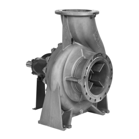
FIG.1 Pompa ad asse nudo / Bare shaft pump / насос со FIG.2 Gruppo completo / Complete set / узел свободным концом вала насоса с электродвигателем FIG.3 Movimentazione - Pompe ad asse nudo / Handling - Bare FIG.4 Movimentazione - Gruppi completi / Handling - Complete sets shaft pumps / Перемещение... - Seite 5 FIG. 7 Fissaggio del gruppo al suolo / Ground fixing of the group / Сборе крепится к земле A: Base in cemento / Concrete base / Бетонное основание B: Fori per tirafondi / Holes for anchor bolt / Отверстия для анкерных болтов C: Tirafondi / Anchor bolts / болты...
- Seite 6 FIG. 9a Raccomandazioni per installazione con aspirazione negativa (“soprabattente”) Recommendations for suction lift installation (“negative suction”) Recomendaciones para instalación con succión negativa (“sobre del nivel del agua”) Recommandations pour l’installation avec aspiration négative (“sur le niveau de l’eau”) Empfehlungen für die Installation mit negativer Ansaugung (“Saughöhe”) Рекомендации...
- Seite 7 FIG. 9b Raccomandazioni per installazione con aspirazione positiva (“sottobattente”) Recommendations for under head installation (positive suction) Recomendaciones para instalación con succión positiva (“sobre el nivel del agua”) Recommandations pour l’installation avec aspiration positive (“sous le niveau de l’eau») Empfehlungen für den Einbau mit positiven Saugleitung (“unter der Wasserlinie”) Рекомендации...
-
Seite 8: Tabelle Tecniche
TAB.I Livelli di rumorosità In condizioni di funzionamento normale (esente da cavitazione). Valori indicativi e soggetti a tolleranza e al motore accoppiato. Noise level under normal operating conditions (without cavitation). Indicative values, subject to tolerance and dependent from the motor coupled. Niveles de ruidosidad: En condiciones de funcionamiento normal (libre de cavitación). - Seite 9 TAB.III Diametri raccomandati per la tubazione in aspirazione Recomended diameters for suction pipe / Diametros recomendados para la tuberia de succion / Diametres recommandes pour la tuyauterie en aspiration / Empfohlene durchmesser fuer das saugrohr / Pекомендованные диаметры для всасывающего трубопровода DN [mm] DN [mm] Aspirazione pompa / Pump suction / Aspiración de la bomba /...
-
Seite 10: Generalità
1. GENERALITÀ Prima di eseguire qualsiasi operazione, leggere attentamente il presente manuale. Il costruttore declina ogni responsabilità per le conseguenze derivanti dalla mancata osservazione delle indicazioni riportate o da uso improprio del prodotto. Le istruzioni e le prescrizioni riportate nel presente manuale riguardano l’esecuzione standard. -
Seite 11: Caratteristiche Tecniche E Impiego
Cuscinetti a sfere, lubrificazione a grasso permanente (di serie) o in bagno d’olio (opzionale) Sistema di tenuta sull’albero: Serie NCB: tenuta meccanica in accordo a EN12756 (di serie), tenuta a baderna (opzionale) Serie NCBK: tenuta a baderna (di serie), : tenuta meccanica in accordo a EN12756 (opzionale). -
Seite 12: Installazione
SAER non si assume responsabilità per contaminazioni causate da trasporto, immagazzinamento, installazione o derivanti dal sistema su cui è installata la pompa. Per installazione e utilizzo corretti seguire le prescrizioni delle normative locali vigenti. LIMITI DI IMPIEGO Passaggio corpi solidi: max 2 mm Contenuto massimo di corpi solidi: 85 g/m (n≤... - Seite 13 LUOGO DI INSTALLAZIONE (Fig. 9) Preparare una base di appoggio in cemento per il gruppo, sopraelevata dell’altezza necessaria (minimo 300 mm). Accertarsi che il piano di appoggio della pompa sia ben consolidato, regolare (in modo che tutti i piedi appoggino) e che la portata di tale piano sia adeguata al peso.
-
Seite 14: Allacciamento Alla Rete Elettrica
- Verifcare lo spostamento radiale dei due semi giunti utilizzando una squadretta o un comparatore (x). - Se necessario, correggere l’allineamento angolare muovendo il motore: o per motori dotati di viti di regolazione nei piedi, girare le viti di livellamento per ottenere l’allineamento corretto. o per motori senza viti di livellamento, l’allineamento deve essere ottenuto posizionando appositi spessori sotto i piedi del motore. -
Seite 15: Collegamento Elettrico
COLLEGAMENTO ELETTRICO ATTENZIONE! Impostare correttamente i valori dei vari dispositivi (protezioni, apparecchiature elettroniche se presenti) 6. MESSA IN SERVIZIO, FUNZIONAMENTO E ARRESTO RIEMPIMENTO E ADESCAMENTO DELLA POMPA Adescamento soprabattente (livello del liquido in aspirazione più basso della pompa) (Fig. 9a) Chiudere la valvola di intercettazione sulla mandata Aprire la valvola di intercettazione sull’aspirazione iii. -
Seite 16: Verifica Della Tenuta
VERIFICA DELLA TENUTA Tenuta meccanica La tenuta meccanica non necessita di regolazioni e/o manutenzione. E’ possibile una perdita di liquido durante i primi istanti di funzionamento causa assestamento della tenuta stessa. Se la perdita non dovesse cessare, fermare il gruppo e ricercarne la causa. Premistoppa a baderna •... -
Seite 17: Lubrificazione Dei Cuscinetti
OPERAZIONI DA ESEGUIRE CIRCA OGNI 3000 H DI FUNZIONAMENTO Verificare: • Le condizioni degli anelli di usura e delle bussole di protezione dell’albero quando presenti; • Le condizioni dell’albero; • Le condizioni della girante. Se necessario, provvedere alla sostituzione dei particolari sopraelencati. LUBRIFICAZIONE DEI CUSCINETTI Il tipo dei cuscinetti è... -
Seite 18: Messa Fuori Servizio E Smaltimento
8. MESSA FUORI SERVIZIO E SMALTIMENTO Al termine della vita operativa della pompa o di alcune sue parti, lo smaltimento deve essere fatto nel rispetto delle normative vigenti. Questo vale anche per il liquido contenuto, con particolare riguardo se è classificato tossico o nocivo, e per l’imballo. Nel caso in cui sia necessario rendere il materiale al fornitore: - svuotare completamente la pompa dal liquido e lavarla accuratamente, - nel caso sia necessario, provvedere ad una completa decontaminazione del prodotto,... -
Seite 19: Parti Di Ricambio
10. PARTI DI RICAMBIO Utilizzare solo parti di ricambio originali. Per le parti di ricambio fare riferimento ai cataloghi o contattare l’assistenza tecnica SAER, specificando tipo di motore, n° di matricola e anno di costruzione rilevabili dalla targa identificativa. Il presente prodotto e’ esente da vizi costruttivi. 11. -
Seite 20: General Information
1. GENERAL INFORMATION Before performing any operation on the machine, it is indispensable that you be completely familiar with the entire use and maintenance manual. The manufacturer declines all responsibility for improper use of the product, for damage caused following operations not contemplated in this manual or unreasonable interventions. -
Seite 21: Technicalspecifications And Use
Ball bearings, permanent grease lubrication (standard) o in oil bath (optional) Shaft seal system: NCB Series: mechanical seal according to EN12756 (standard), soft-packing (optional) NCBK Series: soft-packing (standard), mechanical seal according to EN12756 (optional). For motor features refer to the motor manual. -
Seite 22: Installation
For applications in firefighting equipment follow all the requirements of the UNI 12845 or applicable local regulations. The pumps requested and built for pumping potable water should only be used for this purpose. Verify that the pump is suitable for this application according to the requirements of local regulations. - Seite 23 The connection to the power grid must be done in the respect of the local and national standards of the electric system of the place where the pump is installed. 5.2 PLACE OF INSTALLATION (Fig.9) Prepare a concrete base for the complete set, and raise it, up to the required height (minimum 300 mm). Make sure that the pump’s support surface is solid and even (so that it rests on all the feet) and that the load capacity of the surface is adequate for the weight shown on the plate.
-
Seite 24: Auxiliary Connections
- Check the radial displacement of the two semi-couplings by using a bracket or a comparator (x). - If necessary, correct the angle alignment by moving the motor (through the use of the shims or, through the adjustment screws placed in the feet of the motor, if equipped). -
Seite 25: Electrical Connection
ELECTRICAL CONNECTION WARNING! Set properly the values of the electrical devices (protections, electronic devices etc…). 6. SETTING AT WORK, OPERATION AND STOP FILLING AND PRIMING THE PUMP Priming over head (liquid level on the suction side lower than the pump) (Fig.9a) Close the gate valve on the delivery side Unscrew the venting cap (Fig.6) iii. -
Seite 26: Mechanical Seal
6.5 CHECKING OF THE SEAL MECHANICAL SEAL The mechanical seal does not require regulations and/or maintenance. It’s possible a loss of liquid during the first instants of operation due to the arrangement of the seal. If the loss should not stop, stop the group and research the cause. SOFT PACKING Regulate the tightening of the soft packing after about 30 minutes of working. -
Seite 27: Pump Disassembly
7.3 OPERATIONS NEEDED EVERY 3000 WORKING HOURS Check: The conditions of the shaft protections: wear rings and bushings; • The conditions of the shaft; • The conditions of the impeller. • If necessary, replace the components listed above. 7.4 LUBRICATING THE BEARINGS Il tipo dei cuscinetti è... -
Seite 28: Decomissioning And Disposal
8. DECOMISSIONING AND DISPOSAL At the end of the operating life of the pump/electropump or any of its parts, it must be disposed of in observance of current regulations.In case you need to return the material to the supplier : completely empty the pump from the liquid and wash it carefully −... -
Seite 29: Spare Parts
10. SPARE PARTS Use only original spare parts. To order spare parts, refer to the catalogues or contact the SAER Technical assistance specifying the kind of the motor, the serial number and the year of manufacture (all these data are to be found in the identification plate). This product is free from the manufacturing defects. 11. -
Seite 30: General
1. GENERAL Antes de efectuar cualquier operación, lea atentamente el presente manual. El fabricante declina toda responsabilidad por las consecuencias derivadas del no respeto de las indicaciones aquí descritas o de un uso inadecuado del producto. Las instrucciones y prescripciones del presente manual hacen referencia al modelo estándar. -
Seite 31: Características Técnicas Y Uso
cojinete de bolas, lubricación permanente de grasa (estándar) o en baño de aceite (opcional) Sistema de sellado sobre el eje: o Serie NCB: sello mecanico segun EN12756 (de serie), empaquetadura baderna (opcional) o Serie NCBK: empaquetadura baderna (de serie), sello mecanico segun EN12756 (opcional). -
Seite 32: Instalación
Temperatura del liquido bombeado: min -15°C max 120°C Cantidad maxima de arranques por hora: depende del motor Temperatura ambiente maxima: depende del motor Presion de funcionamiento maxima: consultar la placa de la bomba Para sistemas contra incendios rogamos de seguir todas las prescripciones de la normativa UNI 12845 o de las normativas locales en vigor. Las bombas solicitadas y fabricadas para el bombeo de agua potable tienen que ser utilizadas solamente para esta misma finalidad. - Seite 33 LUGAR DE INSTALACIÓN (Fig.9) Preparar una base de apoyo de cemento para el grupo, elevada a la altura necesaria (mínimo 300 mm). Asegurarse de que el plano de apoyo de la bomba esté bien consolidado, regular (de modo que todos los pies queden apoyados), y que la capacidad de carga de dicho plano sea adecuada al peso.
-
Seite 34: Conexión A La Red Eléctrica
- Comprobar el desplazamiento radial de las dos semijuntas utilizando una escuadra o un comparador (x). - Si fuese necesario, corregir la alineación angular moviendo el motor: para motores con tornillos de regulación en los pies, girar los tornillos de nivelación para nivelar correctamente. para motores sin tornillos de nivelación, la alineación debe realizarse situando los correspondientes espesores bajo los pies del motor. -
Seite 35: Conexión Eléctrica
CONEXIÓN ELÉCTRICA ATENCIÓN! Configurar correctamente los valores de los diferentes dispositivos (protecciones, aparatos electrónicos si están presentes). 6. PUESTA EN SERVICIO, FUNCIONAMIEN RELLENADO Y CEBADO DE LA BOMBA Cebado con succión negativa (nivel del líquido en aspiración más bajo que la bomba) (Fig.9a) Cerrar la válvula de cierre en la salida Abrir la válvula de cierre en la aspiración iii. -
Seite 36: Mantenimiento
COMPROBACIÓN DE LA JUNTA Junta mecánica La junta mecánica no requiere regulaciones ni mantenimiento Es posible que se produzca una pérdida de líquido durante los primeros momentos de funcionamiento a causa de la disposición de la propia junta. Si la pérdida no cesa, detener el grupo y buscar la causa. PRENSAESTOPA CON EMPAQUETADURA •... -
Seite 37: Lubricación De Los Cojinetes
OPERACIONES A EFECTUAR APROX. CADA 3000 h DE FUNCIONAMIENTO Supervisar: • El estado de los anillos de desgaste y de los casquillos de protección del mástil, cuando los haya; • El estado del mástil; • El estado de la turbina. Si es necesario, proceder a la sustitución de los elementos anteriormente indicados. -
Seite 38: Puesta Fuera De Servicio Y Eliminación
8. PUESTA FUERA DE SERVICIO Y ELIMINACIÓN Al final de la vida útil de la bomba o de algunas de sus piezas, la eliminación debe realizarse respetando la normativa vigente. Esto es también aplicable al líquido contenido, especialmente si está clasificado como tóxico o nocivo, y para el embalaje. Si fuese necesario enviar el material al proveedor: - Vaciar por completo la bomba de líquido y limpiarla a fondo, - Si fuese necesario, proceder a la completa descontaminación del producto,... -
Seite 39: Piezas De Recambio
10. PIEZAS DE RECAMBIO Utilizar solo piezas de recambio originales. Consultar las piezas de recambio en los catálogos o contactar con la asistencia técnica de SAER, especificando el tipo de motor, n. ° de matrícula y año de fabricación que aparecen en la placa identificativa. Este producto está exento de defectos de construcción. -
Seite 40: Généralités
1. GÉNÉRALITÉS Avant d’effectuer n’importe quelle opération, lire attentivement le présent manuel. Le constructeur décline toute responsabilité pour les conséquences dérivant du non-respect des recommandations indiquées et d’une utilisation impropre du produit. Les instructions et les prescriptions indiquées dans le présent manuel concernent l’exécution standard. -
Seite 41: Caractéristiques Techniques Et Utilisation
Roulements à billes, lubrification à graisse permanent (de série) ou à bain d’huile (optionnel) Système d’étanchéité sur l’arbre. Série NCB: garniture mécaniques selon EN12756 (de série), garniture à tresse (optionnel) Série NCBK: garniture à tresse (de série), :garniture mécanique selon EN12756 (optionnel). -
Seite 42: Utilisations Non Autorisées
Max température ambiante : il dépend du moteur Pression max de service: se reporter à la plaque signalétique de la pompe Pour les applications dans les équipements anti-incendie, suivre toutes les exigences de la norme UNI 12845 ou réglementations locales.. Les pompes demandées et construites pour le pompage de l’eau potable, doivent être utilisées seulement à... - Seite 43 LIEU D’INSTALLATION (Fig.9) Préparer une base d’appui en ciment pour le groupe, surélevée de la hauteur nécessaire (300 mm minimum). S’assurer que le plan d’appui de la pompe soit bien consolidé, régler (de sorte que tous les pieds d’appui) et que la portée de ce plan soit adaptée au poids.
-
Seite 44: Branchement Au Réseau Électrique
Vérifier le déplacement radial des deux demi-joints en utilisant une équerre ou un comparateur (x). - Si besoin, corriger l’alignement angulaire en déplaçant le moteur: o pour les moteurs équipés de vis de réglage au niveau des pieds, tourner les vis de nivellement pour obtenir l’alignement correct. o pour les moteurs sans vis de nivellement, l’alignement doit être obtenu en positionnant les entretoises appropriées sous les pieds du moteur. -
Seite 45: Branchement Électrique
BRANCHEMENT ÉLECTRIQUE ATTENTION! Régler correctement les valeurs des différents dispositifs (protections, appareils électroniques si présents) 6. MISE EN SERVICE, FONCTIONNEMENT ET ARRÊT REMPLISSAGE ET AMORÇAGE DE LA POMPE Amorçage battant supérieur (niveau du liquide en aspiration plus bas de la pompe) (Fig.9a) Fermer la vanne d’interception sur la tuyauterie de refoulement. -
Seite 46: Vérification De L'étanchéité
VÉRIFICATION DE L’ÉTANCHÉITÉ Étanchéité mécanique L’étanchéité mécanique ne nécessite d’aucun réglage et/ou entretien. Une perte de liquide pendant les premiers instants de fonctionnement est possible, à cause des réglages de l’étanchéité même. Si la perte ne devait pas cesser, arrêter le groupe et rechercher la cause. Presse-étoupe à... -
Seite 47: Démontage De La Pompe
LUBRIFICATION DES ROULEMENTS Le type des roulements est indiqué dans la documentation technique de référence. Les pompes avec roulements prélubrifiés à graisse permanente Les intervalles de remplacement indicatifs sont indiqués dans le TAB.VII (durée prévue selon L Pompes avec roulements graissables Les pompes avec roulements à... -
Seite 48: Mise Hors Service Et Élimination
8. MISE HORS SERVICE ET ÉLIMINATION Au terme de la vie opérationnelle de la pompe ou de certaines parties, l’élimination doit être effectuée dans le respect des normes en vigueur. Cela vaut même pour le liquide contenu, avec une précaution particulière s’il est classé toxique ou nocif, et pour l’emballage. S’il est nécessaire de rendre le matériel au fournisseur: - vider entièrement la pompe du liquide et la laver soigneusement, - s’il devait être nécessaire, procéder à... -
Seite 49: Pièces De Rechange
10. PIÈCES DE RECHANGE Utiliser uniquement les pièces de rechange originales. Pour les pièces de rechange, faire référence aux catalogues ou contacter l’assistance technique SAER, en spécifiant le type de moteur, le n° d’immatriculation et l’année de construction relevables depuis la plaque d’identification. Le présent produit est sans vices de construction. -
Seite 50: Allgemeine Informationen
1. ALLGEMEINE INFORMATIONEN Lesen Sie die vorliegende Anleitung vor der Ausführung jeglicher Arbeiten und Vorgänge bitte sorgfältig durch. Der Hersteller übernimmt keinerlei Haftung für Folgen oder Schäden, die durch Nichtbeachtung der vorliegenden Anweisungen oder durch unsachgemäßen Gebrauch des Produkts entstehen. Die in der vorliegenden Betriebsanleitung angegebenen Anleitungen und Vorschriften beziehen sich auf die Standardausführung. -
Seite 51: Technische Daten Und Einsatz
4. TECHNISCHE DATEN UND EINSATZ PRODUKTBESCHREIBUNG NCB: Zentrifugalpumpe mit axialer Ansaugung und genormten Abmessungen gemaess EN733 NCBK: Zentrifugalpumpe mit axialer Ansaugung und Abmessungen, die die Norm EN733 uebertreffen. NCBZ / NCBKZ: Elektro-Pumpengruppe komplett montiert auf Grundplatte. Pumpe und Motor mittels elastischer Kupplung gekoppelt. -
Seite 52: Unzulässige Anwendungen
Maximale Umgebungstemperatur : es hängt von der Motor ab Maximaler Betriebsdruck : siehe das Typenschild der Pumpe. Die für Trinkwasserförderung hergestellten Pumpen sollten nur für diesen Zweck verwendet werden. Stellen Sie bitte sicher, dass die Anwendung der Pumpen den Anforderungen der örtlichen Vorschriften entsprechen. Die Pumpen müssen vor ihrer ersten Inbetriebnahme und nach dem Austausch von einer oder mehreren Komponenten, die mit dem Fördermedium in Berührung kommen, gereinigt werden. -
Seite 53: Aufstellungsort (Abb.9)
Der Anschluss an das elektrische Netz muss unter Beachtung der für elektrische Anlagen geltenden örtlichen und nationalen Vorschriften des Ortes, an dem die Pumpe installiert wird, erfolgen. 5.2 AUFSTELLUNGSORT (Abb.9) Bereiten Sie eine Grundplatte aus Zement für das Aggregat vor, die um die verlangte Höhe erhöht ist (mindestens 300 mm). Stellen Sie sicher, dass die Auflageplatte der Pumpe fest und eben ist (alle Pumpenfüße müssen aufliegen) und dass die Belastbarkeit der Platte dem Gewicht entspricht. -
Seite 54: Anschluss An Das Elektrische Netz
Prüfen Sie den Radialversatz der beiden Kupplungshälften unter Verwendung eines Winkelstücks oder eines Komparators (x). - Erforderlichenfalls die Winkelausrichtung durch Bewegen des Motors korrigieren. Bei mit Einstellschrauben in den Füßen ausgestatteten Motoren die Nivellierschrauben drehen, um die korrekte Ausrichtung zu erzielen. - Nach Abschluss der Ausrichtung den Kupplungsschutz wieder anbringen. -
Seite 55: Inbetriebnahme, Betrieb Und Abschaltung
ELEKTRISCHER ANSCHLUSS ACHTUNG! Stellen Sie die Werte der verschiedenen Vorrichtungen (Schutzvorrichtungen, elektronische Geräte, falls vorhanden) korrekt ein. 6. INBETRIEBNAHME, BETRIEB UND ABSCHALTUNG AUFFÜLLEN UND ANSAUGENLASSEN DER PUMPE Ansaugenlassen oberhalb des Flüssigkeitsniveaus (der Stand des angesaugten Fördermediums ist niedriger als die Pumpe) (Abb.9a) Druckseitiges Absperrventil schließen Saugseitiges Absperrventil öffnen iii. -
Seite 56: Dichtungsprüfung
6.5 DICHTUNGSPRÜFUNG GLEITRINGDICHTUNG Die Gleitringdichtung erfordert keine Einstellung und/oder Wartung. Es kann sein, dass zu Betriebsbeginn aufgrund des Setzens der Dichtung ein Flüssigkeitsverlust auftritt. Sollte der Flüssigkeitsverlust andauern, das Aggregat stoppen und nach der Ursache suchen. STOPFBUCHSPACKUNG Das Anziehen der Stopfbuchse nach circa 30 Minuten Betriebszeit einstellen. Nach der Einstellung des Anziehens ein paar Minuten warten: Der Flüssigkeitsverlust muss einem leichten Tropfen entsprechen und in jedem Fall kleiner als der sichtbare Verlust vor dem Anziehen sein (etwa zwischen 20 und 100 Tropfen pro Minute). -
Seite 57: Schmierung Der Lager
7.4 SCHMIERUNG DER LAGER Die Art der Lager ist in den technischen Bezugsunterlagen angegeben. Pumpen mit vorgeschmierten Lagern mit Permanentschmierung: Die Lager haben eine Lebensdauerschmierung (mit Fett) und erfordern daher keine Wartung. Die Richtwerte für die empfohlenen Austauschintervalle sind angegeben in TAB. VII (vorgesehene Dauer gemäß L10). Pumpen mit Lagern im Ölbad Pumpen mit Lagern im Ölbad werden ohne Öl im Inneren versandt. -
Seite 58: Ausserbetriebnahme Und Entsorgung
8. AUSSERBETRIEBNAHME UND ENTSORGUNG Am Ende der Lebensdauer der Pumpe oder einiger ihrer Teile muss deren Entsorgung unter Beachtung der geltenden Vorschriften erfolgen. Dies gilt auch für die in ihr enthaltene Flüssigkeit, insbesondere wenn diese als giftig oder gesundheitsschädlich eingestuft ist, sowie für die Verpackung. Erforderlichenfalls das Material an den Lieferanten zurückgeben: die Pumpe vollständig entleeren und sorgfältig spülen;... -
Seite 59: Ersatzteile
10. ERSATZTEILE Verwenden Sie ausschließlich Original-Ersatzteile. Nehmen Sie für die Ersatzteile Bezug auf die Kataloge oder wenden Sie sich an den technischen Kundendienst von SAER; geben Sie dabei den Motortyp, die Seriennummer und das Baujahr an (diese Daten finden Sie auf dem Typenschild). Das vorliegende Produkt ist frei von Herstellungsfehlern. -
Seite 60: Общие Положения
1. ОБЩИЕ ПОЛОЖЕНИЯ Перед выполнение какой-либо операции необходимо внимательно прочитать настоящее руководство. Производитель отклоняет любую ответственность за последствия, связанные с несоблюдением приведенных инструкций или с ненадлежащей эксплуатацией изделия. Инструкции и предписания, приведенные в настоящем руководстве, относятся к стандартному исполнению. Для всех иных исполнений и по любым... -
Seite 61: Описание Машины
Шариковые подшипники с перманентной консистентной смазкой (стандартное исполнение) или в маслянной ванне (по запросу) • Система уплотнения вала: • Серия NCB: механическое уплотнение в соответствии с EN12756 (стандартное испонение), сальниковое уплотнение (по запросу) • NCBK: сальниковое уплотнение (стандартное исполнение), механическое уплотнение в соответствии с EN12756 (по запросу). •... -
Seite 62: Установка
Максимальная температура окружающей среды: в зависимости от двигателя Максимальное рабочее давление: см. табличку насоса Насосы запрашиваются и производятся для перекачки питьевой воды, должны использоваться только для этой цели. Убедитесь, что насос подходит для этого предназначения в соответствии с требованиями действующих местных законов. Насосы должны быть очищены перед их... - Seite 63 МЕСТО УСТАНОВКИ (рис. 9) Для узла электронасоса подготовить опорное основание из цемента, приподнятое на нужную высоту (минимум 300 мм). Убедиться, что опорная поверхность насоса является достаточно прочной, ровной (так, чтобы все четыре ножки имели опору) и что грузоподъемность соответствует весу. Проверить, что...
- Seite 64 - Если нужно исправить угловое выравнивание, для этого перемещают двигатель: o для двигателей, оснащенных регулировочными винтами ножек, вращают винты выравнивания для правильного выравнивания. o для двигателей без регулировочных винтов выравнивание достигается путем размещения специальных прокладок под ножками двигателя. - После того как выравнивание закончено, установите на место накладку. Осевое...
-
Seite 65: Электрические Соединения
ЭЛЕКТРИЧЕСКИЕ СОЕДИНЕНИЯ ВНИМАНИЕ! Правильно настроить различные устройства (защитные устройства, электронную аппаратуру, при наличии) 6. ВВОД В ЭКСПЛУАТАЦИЮ, РАБОТА И ОСТАНОВКА ЗАПОЛНЕНИЕ И ЗАЛИВКА НАСОСА ПЕРЕД ПУСКОМ Заполнение для монтажа не под заливом (уровень жидкости на участке всасывания ниже уровня насоса) (рис.9a.) Закрыть... -
Seite 66: Проверка Герметичности
ПРОВЕРКА ГЕРМЕТИЧНОСТИ Механическое уплотнение Механическое уплотнение не нуждается в регулировке и/или техобслуживании. Возможна утечка жидкости в первые секунды работы, поскольку происходит приработка самого уплотнения. Если утечка не прекращается, необходимо остановить насос и выявить причину. Набивной сальник • Примерно через 30 минут работы необходимо отрегулировать затяжку набивки сальника. •... -
Seite 67: Смазка Подшипников
ОПЕРАЦИИ, ВЫПОЛНЯЕМЫЕ ПРИМЕРНО ЧЕРЕЗ КАЖДЫЕ 3000 ЧАСОВ РАБОТЫ Проверить: • Состояние колец компенсации износа и защитных втулок вала (при наличии); • Состояние вала; • Состояние рабочего колеса. При необходимости – замена вышеперечисленных компонентов. СМАЗКА ПОДШИПНИКОВ Тип подшипников указан в соответствующей технической документации. Насосы, оснащенные... -
Seite 68: Вывод Из Эксплуатации И Утилизация
8. ВЫВОД ИЗ ЭКСПЛУАТАЦИИ И УТИЛИЗАЦИЯ По окончании срока службы насоса или некоторых его частей выполняется утилизация в соответствии с действующими нормативами. Это распространяется также и на содержащуюся в насосе жидкость, с учетом ее классификации как токсичной или вредной, и на упаковочные материалы. -
Seite 69: Запчасти
10. ЗАПЧАСТИ Использовать только фирменные запчасти. Для заказа запчастей следует ознакомиться с каталогами или обратиться в службу техпомощи SAER; при этом указать тип двигателя, заводской номер и год изготовления; эти данные указаны на идентификационной табличке. Настоящая машина не имеет производственных дефектов. 11. - Seite 70 La seguente procedura vale per pompe serie NCB in versione standard. Per tutti gli altri modelli e/o configurazioni, contattare l’assistenza tecnica SAER The following procedure is relevant to the pumps NCB in standard version. For all the other models and/or configurations, to contact SAER technical assistance.
-
Seite 71: Dichiarazione Di Conformità
DÉCLARATION DE CONFORMITÉ La Société SAER Elettropompe S.p.A. dont le siège se trouve à via Circonvallazione, 22 - 42016 Guastalla (Reggio Emilia) - Italie, déclare que les pompes / électropompes avec un seul turbine, pour l’élévation d’eau claire, série NCB... / NCBK…... - Seite 72 POMPE SERIE NCB e NCBZ SERIES NCB AND NCBZ PUMPS • BOMBAS SERIES NCB Y NCBZ • POMPES DES SÉRIES NCB ET NCBZ • PUMPEN SERIE NCB UND NCBZ • N. COMPONENTE COMPONENT COMPONENTE COMPOSANT BAUTEIL Tappo Plug Tapón Bouchon...
- Seite 74 POMPE SERIE NCBK e NCBKZ SERIES NCBK AND NCBKZ PUMPS • BOMBAS SERIES NCBK Y NCBKZ • POMPES DES SÉRIES NCBK ET NCBKZ • PUMPEN SERIE NCBK UND NCBKZ • N. COMPONENTE COMPONENT COMPONENTE COMPOSANT BAUTEIL Tappo Plug Tapón Bouchon Stopfen Guarnizione Gasket...
- Seite 76 • La ditta si riserva la facoltà di modificare senza preavviso i dati riportati in questo manuale. • Saer can alter the data mentioned in this manual without notifications. • Saer se reserva el derecho de modificar los datos indicados en este manual sin previo aviso. •...