
Verwandte Anleitungen für Optika Italy SZ Serie


Inhaltszusammenfassung für Optika Italy SZ Serie
- Seite 1 SZ Series INSTRUCTION MANUAL Model SZX-B SZX-T SZX-BA SZX-TA SZO-B SZO-T SZ-A1 SZ-A6 SZ-ST1 SZ-ST2 SZ-ST3 SZ-ST7 SZ-ST8 SZ-STL1 SZ-STL2 SZ-STLX Ver. 1 .0 2019...
-
Seite 2: Inhaltsverzeichnis
Table of Contents Warning Symbols and conventions Safety Information Intended use Overview System Diagram SZX-B / SZX-T - SZX-BA / SZX-TA SZO-B / SZO-T SZ-A1 SZ-A6 SZ-ST1 SZ-ST2 / SZ-ST3 SZ-T7 / SZ-T8 SZ-STL1 5.10 SZ-STL2 5.11 SZ-STLX Unpacking Assembling SZX-B / SZX-T - SZX-BA / SZX-TA SZO-B / SZO-T SZ-A1... - Seite 3 Microphotography Installing the C-mount adapter 9.2 Use of reflex cameras 10. Maintenance 11. Troubleshooting Equipment disposal Page 3...
-
Seite 4: Symbols And Conventions
Warning This microscope is a scientific precision instrument designed to last for many years with a minimum of maintenance. It is built to high optical and mechanical standards and to withstand daily use. We remind you that this manual contains important information on safety and maintenance, and that it must therefore be made accessible to the instrument users. -
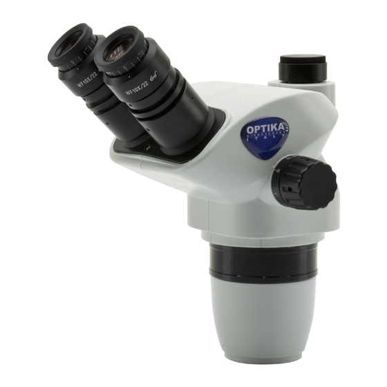
Seite 5: Overview
Overview System Diagram Page 5... -
Seite 6: Szx-B / Szx-T - Szx-Ba / Szx-Ta
SZX-B / SZX-T - SZX-BA / SZX-TA EYEPIECE PHOTO/TV PORT (ONLY SZX-T/TA) DIOPTER COMPENSATION RING KOOM KNOB MICROSCOPE BODY SZX-B/BA: BINOCULAR SZX-T/TA: TRINOCULAR SZO-B / SZO-T EYEPIECE PHOTO/TV PORT (ONLY SZO-T) DIOPTER COMPENSATION RING CLICK STOP SELECTOR MICROSCOPE BODY SZO-B: BINOCULAR SZO-T: TRINOCULAR KOOM KNOB Page 6... -
Seite 7: Sz-A1
SZ-A1 FIXING SCREW FIXING KNOB COARSE FOCUS KNOB HEAD HOLDER SZ-A6 TENSION ADJUSTMENT FIXING SCREW RING FIXING KNOB HEAD HOLDER COARSE FOCUS FOCUS LOCK KNOB LEVER FINE FOCUS KNOB Page 7... -
Seite 8: Sz-St1
SZ-ST1 PILLAR BLACK/WHITE STAGE PLATE BASE STAGE CLIPS SZ-ST2 / SZ-ST3 PILLAR INCIDENT LIGHT ON/OFF - INTENSITY CONTROL KNOB TRANSLUCENT (TRANSMITTED LIGHT) OR BLACK/WHITE (INCIDENT LIGHT) STAGE PLATES BASE STAGE CLIPS INCIDENT LIGHT LED ILLUMINATOR Page 8... -
Seite 9: Sz-T7 / Sz-T8
SZ-T7 / SZ-T8 INCIDENT LIGHT ON/OFF - INTENSITY CONTROL KNOB PILLAR SELF SUPPORTING LED ARMS TRANSLUCENT (TRANSMITTED LIGHT) OR BLACK/WHITE (INCIDENT LIGHT) STAGE PLATES TRANSMITTED LIGHT ON/OFF - INTENSITY CONTROL KNOB BASE STAGE CLIPS SZ-STL1 PILLAR VERTICAL ARM FIXING KNOB HORIZONTAL ARM HOLDER FIXING KNOB... -
Seite 10: Sz-Stl2
5.10 SZ-STL2 HORIZONTAL ARM PILLAR FIXING KNOB HORIZONTAL FIXING KNOB FOR TILTING HOLDING VERTICAL ARM FIXING KNOB DROP PREVENTION RING FOCUS SYSTEM HOLDING ARM BASE 5.11 SZ-STLX PILLAR VERTICAL ARM FIXING KNOB HORIZONTAL HORIZONTAL SLIDING LOCK FIXING SCREW HORIZONTAL ARM FIXING KNOB DROP PREVENTION RING... -
Seite 11: Unpacking
Unpacking The microscope is housed in a moulded Styrofoam container. Remove the tape from the edge of the container and lift the top half of the container. Take some care to avoid that the optical items (objectives and eyepieces) fall out and get damaged. Using both hands (one around the arm and one around the base), lift the microscope from the container and put it on a stable desk. -
Seite 12: Szo-B / Szo-T
SZO-B / SZO-T ① ② ④ ⑤ ③ ① Microscope body ③ Allen wrenches (only for SZO-T) ④ Dust cover (SZO-B Binocular) / SZO-T Trinocular) ② Eyepieces ⑤ Photo tube (only for SZO-T) SZ-A1 ① ① Coarse focus system Page 12... -
Seite 13: Sz-A6
SZ-A6 ① ① Coarse/fine focus system SZ-ST1 ② ③ ① ① Base ③ Black/white plate ② Stage clips (one pair) Page 13... -
Seite 14: Sz-St2 / Sz-St3
SZ-ST2 / SZ-ST3 ① ⑥ ② ③ ⑥ ⑤ ④ ① Base ④ Incident light illuminator ② Transparent disc ⑤ Black/white plate ③ Stage clips (one pair) ⑥ Power supply SZ-ST7 / SZ-ST8 ⑤ ② ③ ① ④ ① Base ④... -
Seite 15: Sz-Stl1
SZ-STL1 ① ② ③ ④ ⑤ ① Base ④ Horizontal arm ② Vertical arm ⑤ Focus holder arm ③ Drop prevention ring SZ-STL2 ④ ② ③ ⑤ ① ⑥ ① Base ④ Horizontal arm ② Vertical arm ⑤ Focus holder arm ③... -
Seite 16: Sz-Stlx
7.10 SZ-STLX ③ ① ② ⑤ ④ ⑥ ① Base ④ Drop prevention ring ② Vertical arm ⑤ Focus system ③ Horizontal arm ⑥ Allen wrenches Page 16... -
Seite 17: Assembling Procedure
7.11 Assembling procedure 7.11.1 SZ-A1 / SZ-A6 • The mounting of the SZ-A1 and SZ-A6 focusing systems applies to all bases except SZ-STL1, ① SZ-STL2 and SZ-STLX. For the assembling pro- cedure on these bases, please refer to the speci- fic section. -
Seite 18: Sz-St7 / Sz-St8
3. Connect the power supply plug to the socket on the back of the microscope base. (Fig. 4) F ig. 4 ig. 4 7.11.4 SZ-ST7 / SZ-ST8 1. Remove the base from its packaging and place it on a flat surface. The base is already assembled from the factory and does not require any further assembly procedure other than that of mounting the focusing system. - Seite 19 3. Insert the drop preventing ring and fix it at the de- sired height by screwing the fixing knob. (Fig. 7) F ig. 7 ig. 7 4. Insert the horizontal arm and secure it with the fixing screw ①. (Fig. 8 - 9) F ig.
- Seite 20 6. Once fully inserted, tighten the fixing screw ④ (Fig. 11) ④ F ig. 11 ig. 11 7. Insert from below the focusing system, tighten the fixing screw ⑤ and re-tighten the locking knob ③ from below. (Fig. 12-13) ⑤ F ig.
-
Seite 21: Sz-Stl2
7.11.6 SZ-STL2 1. Screw the pillar on the base. (Fig. 14) F ig. 14 ig. 14 2. Tighten the screw to lock the pillar. (Fig. 15) F ig. 15 ig. 15 3. Insert the drop preventing ring and fix it at the de- sired height by screwing the fixing knob. - Seite 22 5. For a bigger safety, lock the fixing screw ② with ② the provided Allen wrench. (Fig. 18) F ig. 18 ig. 18 6. Install the head holder. Unscrew the prevention knob ③ and insert the head holder from below in the vertical arm.
-
Seite 23: Sz-Stlx
7.11.7 SZ-STLX 1. Screw the pillar on the base. (Fig. 21) F ig. 21 ig. 21 2. Tighten the screw to lock the pilla. (Fig. 22) F ig. 22 ig. 22 3. Insert the drop preventing ring and fix it at the de- sired height by screwing the fixing knob. - Seite 24 5. Head holder can be installed in several ways according to specific need of the user. Installation mode n° 1: (Fig. 25-27) Insert the rear part of the head support (round black part) ③ (Fig. 25) from the top into the hole of the horizontal arm ④...
-
Seite 25: Installing The Head (All Models)
• These two modes allow the tilting of the head. (Fig. 29) F ig. 29 ig. 29 Installation mode n° 3: (Fig. 30) Insert the back part of the head holder (black round part) ③ (Fig. 25) in the hole at the end of the horizontal arm and tighten the knob ⑤. -
Seite 26: Installing The Eyepieces (All Models)
7.11.9 Installing the eyepieces (all models) ① 1. Remove the dust caps from the eyepiece sleeves and insert the eyepieces. (Fig. 33) 2. Lock the eyepieces by tightening the locking screw ①. F ig. 33 ig. 33 7.11.10 Installing the photo port (SZX-T/TA) ①... -
Seite 27: Using The Microscope
Using the microscope Adjusting interpupillary distance Hold the right and left eyepiece tube with both hands and adjust the interpupillary distance by moving the two parts until one circle of light can be seen. If two circles appear, the interpupillary distance is too big, and if two overlapped circles appear, the interpupilla- ry distance is too small. -
Seite 28: Focus Lock Lever (Sz-A6)
Focus lock lever (SZ-A6) The lock lever serves as the focus memory function. After focusing the sample, pull the lever ① towards the front of the microscope and lock it. (Fig. 40). This defines the upper focus point. Now you can move the focus of the microscope with the coarse knob, replace the sample and then bring the system back to the upper point: the sample will be... -
Seite 29: Use Of Additional Lens
8.6 Magnification 1. Select the desired magnification by adjusting the zoom knob ①. (Fig. 41) • Change the eyepieces and/or add an appropriate additional lens if needed. • Only for SZO series: The microscope body is equipped with a “click-stop” function that allows to obtain a precise setting of the desired magnification (Fig. -
Seite 30: Use Of Additional Lenses 0.3X-0.5X
Serie SZO (0.67x - 4.5x / F.N. 23mm) Eyepiece Field Number (mm) Objective Total Mag. Field Of View Total Mag. Field Of View Total Mag. Field Of View Total Mag. Field Of View (mm) (mm) (mm) (mm) 0.3X 2.01X-13.5X 114.43-17.04 3.02X-20.25X 79.60-11.85 4.02X-27X 59.70 -8.89 5.03X-33.75X 44.78-6.67 0.5X 3.35X-22.5X 68.66-10.22... -
Seite 31: Use Of Illumination (Sz-St2/3/7/8)
8.10 Use of illumination (SZ-ST2/3/7/8) ① 1. Turn the transmitted light knob ① in order to turn ON/OFF or to change the intensity of the transmit- ted light LED. (Fig. 48) 2. Turn the incident light knob ② in order to turn ON/ OFF or to change the intensity of the incident light LED. -
Seite 32: Use Of Overhanging Stand (Sz-Stl1/2/X)
8.12 Use of overhanging stand (SZ-STL1/2/X) 8.12.1 SZ-STL1 Moving the horizontal arm 1. Unlock the knob on the right side of the horizontal arm ①. (Fig. 52) ① F ig. 52 ig. 52 2. The arm can be extended or shortened according to specific needs. -
Seite 33: Sz-Stl2
8.11.2 SZ-STL2 Moving the horizontal arm 1. Unlock the knob on the left side of the horizontal arm ①. (Fig. 56) F ig. 56 ig. 56 ① 2. The arm can be extended or shortened according to specific needs. (Fig. 57) F ig. -
Seite 34: Sz-Stlx
F ig. 60 ig. 60 Rotating the horizontal arm 1. Loosen the horizontal arm fixing knob ④ and rotate the arm, then tighten again the knob. (Fig. • NOTE: 180° rotation of the microscope with respect to the base could cause a rollover of ④... - Seite 35 Adjusting the horizontal block 1. Unlock the fixing knob of the stopper ② and move it in a position suitable to user’s needs. (Fig. 64) 2. Lock the fixing knob to set the movement limit. ② F ig. 64 ig. 64 Tilting the head holder 1.
- Seite 36 Rotating the horizontal arm ⑤ 1. Loosen the horizontal arm fixing knob ⑤ and rotate the arm, then tighten again the knob. (Fig. • NOTE: 180° rotation of the microscope with respect to the base could cause a rollover of the entire system.
-
Seite 37: Use Of Reflex Cameras
Microphotography Installing the C-mount adapter 1. Loosen the clamping screw ① on the trinocular port and remove the dust cap ②. (Fig. 69) ② ② ① ① F ig. 69 ig. 69 2. Screw the C-mount adapter ③ to the camera ④ and insert the round dovetail of the C-mount into the empty hole of the trinocular port (Fig. - Seite 38 10. Maintenance Microscopy environment This microscope is recommended to be used in a clean, dry and shock free environment with a temperature of 5°-40°C and a maximum relative humidity of 75 % (non condensing). Use a dehumidifier if needed. To think about when and after using the microscope •...
- Seite 39 11. Troubleshooting Review the information in the table below to troubleshoot operating problems. PROBLEM CAUSE SOLUTION I. Optical Section: The illumination is ON, but the field of The plug is not connected to the il- Connect the cable view is dark. lumination The brightness is too low Adjust to a proper setting...
-
Seite 40: Equipment Disposal
Equipment disposal Art.13 Dlsg 25 July 2005 N°151. “According to directives 2002/95/EC, 2002/96/EC and 2003/108/EC relating to the reduction in the use of hazardous substances in electrical and electronic equipment and waste disposal.” The basket symbol on equipment or on its box indicates that the product at the end of its useful life should be collected separately from other waste. - Seite 41 OPTIKA S.r.l. ® Via Rigla, 30 - 24010 Ponteranica (BG) - ITALY Tel.: +39 035.571.392 info@optikamicroscopes.com - www.optikamicroscopes.com OPTIKA Spain spain@optikamicroscopes.com OPTIKA USA usa@optikamicroscopes.com OPTIKA China china@optikamicroscopes.com OPTIKA India india@optikamicroscopes.com OPTIKA Central America camerica@optikamicroscopes.com...
- Seite 42 Serie SZ MANUALE DI ISTRUZIONI Modello SZX-B SZX-T SZX-BA SZX-TA SZO-B SZO-T SZ-A1 SZ-A6 SZ-ST1 SZ-ST2 SZ-ST3 SZ-ST7 SZ-ST8 SZ-STL1 SZ-STL2 SZ-STLX Ver. 1 .0 2019...
- Seite 43 Indice Avvertenza Simboli Informazioni sulla sicurezza Utilizzo previsto Panoramica Diagramma di Sistema SZX-B / SZX-T - SZX-BA / SZX-TA SZO-B / SZO-T SZ-A1 SZ-A6 SZ-ST1 SZ-ST2 / SZ-ST3 SZ-T7 / SZ-T8 SZ-STL1 5.10 SZ-STL2 5.11 SZ-STLX Disimballaggio Assemblaggio SZX-B / SZX-T - SZX-BA / SZX-TA SZO-B / SZO-T SZ-A1 SZ-A6...
- Seite 44 9. Microfotografia Uso di telecamere a passo “C” 9.2 Uso di fotocamere Reflex 10. Manutenzione 11. Guida alla risoluzione dei problemi Smaltimento Pagina 44...
-
Seite 45: Simboli
Avvertenza Questo microscopio è uno strumento scientifico di alta precisione, progettato per durare a lungo con una mini- ma manutenzione; la realizzazione è secondo i migliori standard ottici e meccanici, per poter essere utilizzato quotidianamente. Vi ricordiamo che questo manuale contiene informazioni importanti per la sicurezza e per la manutenzione dello strumento, e deve quindi essere messo a disposizione di coloro che lo utilizzeranno. -
Seite 46: Panoramica
Panoramica Diagramma di Sistema Pagina 46... -
Seite 47: Szx-B / Szx-T - Szx-Ba / Szx-Ta
SZX-B / SZX-T - SZX-BA / SZX-TA OCULARE USCITA FOTO (SOLO SZX-T/TA) ANELLO COMPENSAZIONE DIOTTRICA SELETTORE ZOOM CORPO MICROSCOPIO SZX-B/BA: BINOCULARE SZX-T/TA: TRINOCULARE SZO-B / SZO-T OCULARE USCITA FOTO (SOLO SZO-T) ANELLO COMPENSAZIONE SELETTORE DIOTTRICA CLIC STOP CORPO MICROSCOPIO SZO-B: BINOCULARE SZO-T: TRINOCULARE SELETTORE ZOOM... -
Seite 48: Sz-A1
SZ-A1 VITE DI FISSAGGIO MANOPOLA DI FISSAGGIO MANOPOLA DI MESSA A FUOCO MACRO SUPPORTO TESTA SZ-A6 GHIERA VITE DI REGOLAZIONE FISSAGGIO TENSIONE MANOPOLA DI FISSAGGIO SUPPORTO TESTA MANOPOLA DI LEVA BLOCCO DI MESSA A FUOCO MESSA A FUOCO MACRO MANOPOLA DI MESSA A FUOCO MICRO Pagina 48... -
Seite 49: Sz-St1
SZ-ST1 COLONNA PIATTELLO BIANCO/NERO BASE MOLLETTINE SZ-ST2 / SZ-ST3 COLONNA MANOPOLA ON/OFF E REGOLAZIONE INTENSITÀ LUCE TRASMESSA PIATTELLO TRASLUCIDO (LUCE TRASMESSA) O PIATTELLO BIANCO/NERO MANOPOLA ON/OFF E (LUCE INCIDENTE) REGOLAZIONE INTENSITÀ LUCE INCIDENTE BASE ILLUMINATORE LED MOLLETTINE LUCE INCIDENTE Pagina 49... -
Seite 50: Sz-T7 / Sz-T8
SZ-T7 / SZ-T8 MANOPOLA ON/OFF E REGOLAZIONE INTENSITÀ LUCE TRASMESSA COLONNA BRACCI LED AUTOPORTANTI PIATTELLO TRASLUCIDO (LUCE TRASMESSA) O PIATTELLO BIANCO/NERO (LUCE INCIDENTE) MANOPOLA ON/OFF E REGOLAZIONE INTENSITÀ LUCE INCIDENTE BASE MOLLETTINE SZ-STL1 COLONNA MANOPOLA DI FISSAGGIO BRACCIO VERTICALE BRACCIO ORIZZONTALE MANOPOLA DI FISSAGGIO... -
Seite 51: Sz-Stl2
5.10 SZ-STL2 MANOPOLA DI FISSAGGIO COLONNA BRACCIO ORIZZONTALE BRACCIO ORIZZONTALE MANOPOLA DI FISSAGGIO MANOPOLA DI FISSAGGIO INCLINAZIONE BRACCIO VERTICALE BRACCIO DI SUPPORTO ANELLO DI PREVENZIONE DISCESA BRACCIO DI SUPPORTO SISTEMA DI MESSA A FUOCO BASE 5.11 SZ-STLX COLONNA MANOPOLA DI FISSAGGIO BRACCIO VERTICALE BRACCIO ORIZZONTALE... -
Seite 52: Assemblaggio
Disimballaggio Il microscopio si trova in un imballaggio di polistirolo espanso stampato. Dopo aver tolto il nastro adesivo da tutti gli imballi, sollevare la metà superiore dell’imballaggio. Fare attenzione a non far cadere o danneggiare i com- ponenti ottici (obiettivi e oculari). Estrarre il microscopio dal suo imballaggio con entrambe le mani (una intorno al braccio e una intorno alla base) e appoggiarlo su un piano stabile. -
Seite 53: Szo-B / Szo-T
SZO-B / SZO-T ① ② ④ ⑤ ③ ① Corpo del microscopio ③ Brugola (solo per SZO-T) ④ Copertina antipolvere (SZO-B Binoculare) / SZO-T Trinoculare) ② Oculari ⑤ Foto tubo (solo per SZO-T) SZ-A1 ① ① Messa a fuoco macro Pagina 53... -
Seite 54: Sz-A6
SZ-A6 ① ① Messa a fuoco macro-micro SZ-ST1 ② ③ ① ① Base ③ Disco bianco / nero ② Mollettine (una coppia) Pagina 54... -
Seite 55: Sz-St2 / Sz-St3
SZ-ST2 / SZ-ST3 ① ⑥ ② ③ ⑥ ⑤ ④ ① Base ④ Illuminatore luce incidente ② Disco opalino ⑤ Disco bianco / nero ③ Mollettine (una coppia) ⑥ Alimentatore SZ-ST7 / SZ-ST8 ⑤ ② ③ ① ④ ① Base ④... -
Seite 56: Sz-Stl1
SZ-STL1 ① ② ③ ④ ⑤ ① Base ④ Braccio orizzontale ② Braccio verticale ⑤ Braccio di supporto messa a fuoco ③ Anello prevenzione discesa SZ-STL2 ④ ② ③ ⑤ ① ⑥ ① Base ④ Braccio orizzontale ② Braccio verticale ⑤... -
Seite 57: Sz-Stlx
7.10 SZ-STLX ③ ① ② ⑤ ④ ⑥ ① Base ④ Anello prevenzione discesa ② Braccio verticale ⑤ Messa a fuoco ③ Braccio orizzontale ⑥ Brugole Pagina 57... -
Seite 58: Procedura Di Montaggio
7.11 Procedura di montaggio 7.11.1 SZ-A1 / SZ-A6 • Il montaggio dei sistemi di messa a fuoco SZ-A1 e SZ-A6 si applica a tutte le basi tranne SZ-STL1, ① SZ-STL2 e SZ-STLX. Per il montaggio su queste basi si rimanda al paragrafo specifico. 1. -
Seite 59: Sz-St7 / Sz-St8
3. Collegare lo spinotto dell’alimentatore al connet- tore posto nella parte posteriore della base del microscopio. (Fig. 4) F ig. 4 ig. 4 7.11.4 SZ-ST7 / SZ-ST8 1. Rimuovere la base dal suo imballo e posizionarla su una superficie piana. La base arriva già mon- tata dalla fabbrica e non necessita di ulteriore procedura di montaggio, se non quella del mon- taggio del sistema di messa a fuoco. - Seite 60 3. Inserire l’anello di prevenzione discesa e fissarlo all’altezza desiderata avvitando la manopola di fissaggio. (Fig. 7) F ig. 7 ig. 7 4. Inserire il braccio orizzontale e bloccarlo con la vite di fissaggio ①. (Fig. 8 - 9) F ig. 8 ig.
- Seite 61 6. Una volta inserito a fondo bloccare la vite di fis- saggio ④. (Fig. 11) ④ F ig. 11 ig. 11 7. Inserire dal basso il sistema di messa a fuoco, serrare la vite di fissaggio ⑤ ed avvitare nuova- mente la manopola di blocco ③...
-
Seite 62: Sz-Stl2
7.11.6 SZ-STL2 1. Avvitare la colonna alla base. (Fig. 14) F ig. 14 ig. 14 2. Avvitare le viti per bloccare la colonna. (Fig. 15) F ig. 15 ig. 15 3. Inserire l’anello di prevenzione discesa e fissarlo all’altezza desiderata avvitando la manopola di fissaggio. - Seite 63 5. Per una maggiore sicurezza, serrare la vite di fis- ② saggio ② con la brugola in dotazione. (Fig. 18) F ig. 18 ig. 18 6. Installare il sistema di messa a fuoco. Svitare la manopola di blocco ③ ed inserire il supporto ④ dal basso nel braccio verticale.
-
Seite 64: Sz-Stlx
7.11.7 SZ-STLX 1. Avvitare la colonna alla base. (Fig. 21) F ig. 21 ig. 21 2. Avvitare le viti per bloccare la colonna. (Fig. 22) F ig. 22 ig. 22 3. Inserire l’anello di prevenzione discesa e fissarlo all’altezza desiderata avvitando la manopola di fissaggio. - Seite 65 5. Il supporto testa può essere installato in diversi modi a seconda delle specifiche esigenze dell’utente. Modo di installazione n° 1: (Fig. 25-27) Inserire la parte posteriore del supporto testa (parte rotonda nera) ③ (Fig. 25) dall’alto nel foro del braccio orizzontale ④...
-
Seite 66: Installare La Testa (Tutti I Modelli)
• Queste due modalità consentono l’inclinazione della testa. (Fig. 29) F ig. 29 ig. 29 Modo di installazione n° 3: (Fig. 30) Inserire la parte posteriore del supporto testa (parte rotonda nera) ③ nel foro all’estremità del braccio orizzontale e serrare la manopola ⑤. ⑤... -
Seite 67: Installare Gli Oculari (Tutti I Modelli)
7.11.9 Installare gli oculari (tutti i modelli) ① 1. Rimuovere i tappi antipolvere dai portaoculari ed inserire gli oculari. (Fig. 33) 2. Bloccare gli oculari serrando la vitina di bloccag- gio ①. F ig. 33 ig. 33 7.11.10 Installare l’uscita foto (SZX-T/TA) ①... -
Seite 68: Uso Del Microscopio
Uso del microscopio Regolazione della distanza interpupillare 1. Afferrare con entrambe le mani i portaoculari de- stro e sinistro e regolare la distanza interpupillare spostando i tubi fino a che si osserva una sola immagine (Fig. 36). • Se si osservano due immagini la distanza è trop- po elevata. -
Seite 69: Compensazione Diottrica
Leva di blocco messa a fuoco (SZ-A6) • La leva di blocco svolge la funzione di memoria di messa a fuoco. 1. Dopo avere messo a fuoco il campione, tirare verso la parte anteriore del microscopio la leva ① e bloccarla (Fig. 40). •... - Seite 70 Ingrandimento 1. Selezionare l’ingrandimento desiderato mediante il selettore zoom ②. (Fig. 41) • necessario usare oculari diversi un’adeguata lente addizionale per ottenere l’ingrandimento voluto. • Solo per serie SZO: Il corpo del microscopio della è dotato di una funzione “clic stop” che consente di ottenere un ingrandimento preciso (Fig.
-
Seite 71: Uso Delle Lenti Addizionali 0.3X-0.5X
Serie SZO (0.67x - 4.5x / F.N. 23mm) Oculare Indice di campo (mm) Obiettivo Ingr. Totale Campo visivo Ingr. Totale Campo visivo Ingr. Totale Campo visivo Ingr. Totale Campo visivo (mm) (mm) (mm) (mm) 0.3X 2.01X-13.5X 114.43-17.04 3.02X-20.25X 79.60-11.85 4.02X-27X 59.70 -8.89 5.03X-33.75X 44.78-6.67 0.5X 3.35X-22.5X 68.66-10.22 5.03X-33.75X 47.76-7.11 6.7X-45X... -
Seite 72: Uso Dell'illuminazione (Sz-St2/3/7/8)
8.10 Uso dell’illuminazione (SZ-ST2/3/7/8) ① 1. Ruotare la manopola della luce incidente ① per accendere/spegnere o regolare l’intensità luminosa del LED incidente. (Fig. 48) 2. Ruotare la manopola della luce trasmessa ② per accendere/spegnere o regolare l’intensità luminosa del LED per luce trasmessa. •... -
Seite 73: Uso Delle Basi A Sbalzo (Sz-Stl1/2/X)
8.12 Uso delle basi a sbalzo (SZ-STL1/2/X) 8.12.1 SZ-STL1 Spostare il braccio orizzontale 1. Allentare le manopole sulla parte destra del braccio orizzontale ①. (Fig. 52) ① F ig. 52 ig. 52 2. Il braccio può essere allungato o accorciato in base alle specifiche esigenze. -
Seite 74: Sz-Stl2
8.12.2 SZ-STL2 Spostare il braccio orizzontale 1. Allentare la manopola sulla parte sinistra del braccio orizzontale ①. (Fig. 56) F ig. 56 ig. 56 ① 2. Il braccio può essere allungato o accorciato in base alle specifiche esigenze. (Fig. 57) F ig. -
Seite 75: Sz-Stlx
F ig. 60 ig. 60 Ruotare il braccio orizzontale 1. Allentare la vite di fissaggio del braccio orizzontale ④ e ruotare il braccio, quindi serrare la vite di fissaggio. (Fig. 61) • NOTA: Una rotazione del microscopio di 180° rispetto alla base potrebbe causare un rovesciamento di tutto il sistema. - Seite 76 Regolazione del blocco orizzontale 1. Sbloccare la manopola di fissaggio del blocco ② e spostarla in una posizione adatta alle esigenze dell’utente. (Fig. 64) 2. Bloccare la manopola di fissaggio per impostare il limite di movimento. ② F ig. 64 ig.
- Seite 77 Ruotare il braccio orizzontale ⑤ 1. Allentare la manopola di fissaggio del braccio orizzontale ⑤ e ruotare il braccio, quindi stringere nuovamente la manopola. (Fig. 68) • NOTA: la rotazione di 180° del microscopio rispetto alla base potrebbe causare un ribaltamento dell’intero sistema.
-
Seite 78: Uso Di Fotocamere Reflex
9. Microfotografia Uso di telecamere a passo “C” 1. Allentare la vite di bloccaggio ① sul tubo trinoculare e rimuovere il tappo antipolvere ②. ② ② (Fig. 69) ① ① F ig. 69 ig. 69 2. Avvitare l’adattatore passo C ③ alla telecamera ④... - Seite 79 10. Manutenzione Ambiente di lavoro Si consiglia di utilizzare il microscopio in un ambiente pulito e secco, privo di urti, ad una temperatura fra 0°C e 40°C e con una umidità relativa massima dell’85% (in assenza di condensazione). Si consiglia l’uso di un deumidificatore se necessario.
-
Seite 80: Guida Alla Risoluzione Dei Problemi
11. Guida alla risoluzione dei problemi Consultare le informazioni riportate nella tabella seguente per risolvere eventuali problemi operativi. PROBLEMA CAUSA SOLUZIONE I. Sezione Ottica: Il LED è acceso, ma il campo visivo è L’alimentatore è scollegato. Collegarlo scuro La luminosità è troppo bassa Regolarla ad un livello adeguato I bordi del campo visivo sono vignettati L’illuminatore per luce incidente non è... -
Seite 81: Smaltimento
Smaltimento Ai sensi dell’articolo 13 del decreto legislativo 25 luglio 2005 n°151. “Attuazione delle direttive 2002/95/CE, 2002/96/CE e 2003/108/CE, relative alla riduzione dell’uso di sostanze pericolose nelle apparecchiature elettri- che ed elettroniche, nonché allo smaltimento dei rifiuti”. Il simbolo del cassonetto riportato sulla apparecchiatura o sulla sua confezione indica che il prodotto alla fine della propria vita utile deve essere raccolto separatamente degli altri rifiuti. - Seite 82 OPTIKA S.r.l. ® Via Rigla, 30 - 24010 Ponteranica (BG) - ITALY Tel.: +39 035.571.392 info@optikamicroscopes.com - www.optikamicroscopes.com OPTIKA Spain spain@optikamicroscopes.com OPTIKA USA usa@optikamicroscopes.com OPTIKA China china@optikamicroscopes.com OPTIKA India india@optikamicroscopes.com OPTIKA Central America camerica@optikamicroscopes.com...
- Seite 83 Serie SZ MANUAL DE INSTRUCCIONES Modelo SZX-B SZX-T SZX-BA SZX-TA SZO-B SZO-T SZ-A1 SZ-A6 SZ-ST1 SZ-ST2 SZ-ST3 SZ-ST7 SZ-ST8 SZ-STL1 SZ-STL2 SZ-STLX Ver. 1 .0 2019...
- Seite 84 Índice Advertencia Símbolos Información de seguridad Utilización Vista General Diagrama del Sistema SZX-B / SZX-T - SZX-BA / SZX-TA SZO-B / SZO-T SZ-A1 SZ-A6 SZ-ST1 SZ-ST2 / SZ-ST3 SZ-ST7 / SZ-ST8 SZ-STL1 5.10 SZ-STL2 5.11 SZ-STLX Desembalaje Montaje SZX-B / SZX-T - SZX-BA / SZX-TA SZO-B / SZO-T SZ-A1 SZ-A6...
- Seite 85 Microfotografía Uso de cámaras de paso “C” 9.2 Uso de cámara Reflex 10. Mantenimiento 11. Guía de solución de problemas Medidas ecológicas y reciclaje Página 85...
-
Seite 86: Información De Seguridad
Advertencia Este microscopio es un instrumento científico de precisión. Su utilización está pensada para una larga duración con un mínimo nivel de mantenimiento. Para su fabricación se han utilizado elementos ópticos y mecánicos de elevada calidad que lo convierten en el instrumento ideal para la utilización diaria en las aulas y el laboratorio. Informamos que esta guía contiene importantes informaciones sobre la seguridad y el mantenimiento del pro- ducto y por lo tanto debe ser accesible a todos aquellos que utilizan dicho instrumento. -
Seite 87: Vista General
Vista General Diagrama del Sistema Página 87... -
Seite 88: Szx-B / Szx-T - Szx-Ba / Szx-Ta
SZX-B / SZX-T - SZX-BA / SZX-TA OCULAR PUERTO DE FOTO/TV (SÓLO SZX-T/TA) ANILLO DE COMPENSACIÓN DIÓPTRICA MANDO ZOOM CUERPO MICROSCOPIO SZX-B/BA: BINOCULAR SZX-T/TA: TRINOCULAR SZO-B / SZO-T OCULAR PUERTO DE FOTO/TV (SÓLO SZO-T) ANILLO DE COMPENSACIÓN DIÓPTRICA SELECTOR DE CLICK STOP CUERPO MICROSCOPIO SZO-B: BINOCULAR... -
Seite 89: Sz-A1
SZ-A1 TORNILLO DE FIJACIÓN PERILLA DE FIJACIÓN MANDO DE ENFOQUE MACRO SOPORTE CABEZAL SZ-A6 TUERCA DE TORNILLO DE REGULACIÓN FIJACIÓN DE TENSIÓN PERILLA DE FIJACIÓN SOPORTE CABEZAL MANDO DE PALANCA DEL ENFOQUE BLOQUE DE MACRO ENFOQUE MANDO DE ENFOQUE MICRO Página 89... -
Seite 90: Sz-St1
SZ-ST1 PILAR PLACA BLANCA/ NEGRA BASE PINZAS DE MUESTRA SZ-ST2 / SZ-ST3 PILAR BOTÓN ON/OFF - CONTROL DE INTENSIDAD DE LA LUZ TRANSMITIDA PLACA TRANSLÚCIDA (LUZ TRANSMITIDA) O PLACA BLANCA/NEGRA BOTÓN ON/OFF - CONTROL (LUZ INCIDENTE) DE INTENSIDAD DE LA LUZ INCIDENTE BASE PINZAS DE... -
Seite 91: Sz-St7 / Sz-St8
SZ-ST7 / SZ-ST8 BOTÓN ON/OFF - CONTROL DE INTENSIDAD DE LA LUZ TRANSMITIDA PILAR BRAZOS AUTOPORTANTES CON LEDS PLACA TRANSLÚCIDA (LUZ TRANSMITIDA) O PLACA BLANCA/NEGRA (LUZ INCIDENTE) BOTÓN ON/OFF - CONTROL DE INTENSIDAD DE LA LUZ INCIDENTE BASE PINZAS DE MUESTRA SZ-STL1 PILAR... -
Seite 92: Sz-Stl2
5.10 SZ-STL2 POMO DE FIJACIÓN PILAR BRAZO HORIZONTAL BRAZO HORIZONTAL POMO DE FIJACIÓN PARA POMO DE FIJACIÓN LA INCLINACIÓN BRAZO VERTICAL DEL BRAZO DE SOPORTE ANILLO DE PREVENCIÓN DE CAÍDAS BRAZO DE SOPORTE DEL SISTEMA DE ENFOQUE BASE 5.11 SZ-STLX PILAR POMO DE FIJACIÓN BRAZO VERTICAL... -
Seite 93: Desembalaje
Desembalaje El microscopio esta embalado dentro de una caja de porexpan. Quitar el precinto que hay alrededor de la caja y abrirla. Tenga cuidado al abrir la caja ya que algunos accesorios ópticos como objetivos y oculares podrían caerse o dañarse. Con las dos manos (una sujetando el brazo y la otra la base) extraer el microscopio de dentro la caja de porexpan y poner sobre la mesa, procurando que ésta sea fuerte y estable. -
Seite 94: Szo-B / Szo-T
SZO-B / SZO-T ① ② ④ ⑤ ③ ① Cuerpo del microscopio ③ Llave Allen (sólo para SZO-T) (SZO-B Binocular) / SZO-T Trinocular) ④ Cubierta protectora ② Oculares ⑤ Foto tubo (sólo para SZO-T) SZ-A1 ① ① Enfoque Macro Página 94... -
Seite 95: Sz-A6
SZ-A6 ① ① Enfoque Macro/Micro SZ-ST1 ② ③ ① ① Base ③ Placa blanca/negra ② Pinzas de muestras (una pareja) Página 95... -
Seite 96: Sz-St2 / Sz-St3
SZ-ST2 / SZ-ST3 ① ⑥ ② ③ ⑥ ⑤ ④ ① Base ④ Iluminador luz incidente ② Placa opalina ⑤ Placa blanca/negra ③ Pinzas de muestras (una pareja) ⑥ Fuente de alimentación SZ-ST7 / SZ-ST8 ⑤ ② ③ ① ④ ①... -
Seite 97: Sz-Stl1
SZ-STL1 ① ② ③ ④ ⑤ ① Base ④ Brazo horizontal ② Brazo vertical ⑤ Brazo de soporte de enfoque ③ Anillo de prevención de descenso SZ-STL2 ④ ② ③ ⑤ ① ⑥ ① Base ④ Brazo horizontal ② Brazo vertical ⑤... -
Seite 98: Sz-Stlx
7.10 SZ-STLX ③ ① ② ⑤ ④ ⑥ ① Base ④ Anillo de prevención de descenso ② Brazo vertical ⑤ Enfoque ③ Brazo horizontal ⑥ Llave Allen Página 98... -
Seite 99: Montaje Del Microscopio
7.11 Montaje del microscopio 7.11.1 SZ-A1 / SZ-A6 • El montaje de los sistemas de enfoque SZ-A1 y SZ-A6 se aplica a todas las bases excepto SZ- ① STL1, SZ-STL2 y SZ-STLX. Para el montaje en estas bases, consulte la sección específica. 1. -
Seite 100: Sz-St7 / Sz-St8
3. Conecte el enchufe de la fuente de alimentación al conector situado en la parte posterior de la base del microscopio. (Fig. 4) F ig. 4 ig. 4 7.11.4 SZ-ST7 / SZ-ST8 1. Retire la base de su embalaje y colóquela sobre una superficie plana. - Seite 101 3. Inserte el anillo de prevención de caídas y fíjelo a la altura deseada atornillando el pomo de fi- jación. (Fig. 7) F ig. 7 ig. 7 4. Insertar el brazo horizontal y fijarlo con el tornillo de fijación ①. (Fig. 8 - 9) F ig.
- Seite 102 6. Una vez insertado completamente, apriete el tor- nillo de fijación ④ (Fig. 11) ④ F ig. 11 ig. 11 7. Inserte el sistema de enfoque desde abajo, apriete el tornillo de fijación ⑤ y vuelva a apretar la perilla de bloqueo ③ desde abajo. (Fig. 12-13) ⑤...
-
Seite 103: Sz-Stl2
7.11.6 SZ-STL2 1. Atornille el pilar a la base. (Fig. 14) F ig. 14 ig. 14 2. Apriete los tornillos para bloquear el pilar. (Fig. F ig. 15 ig. 15 3. Inserte el anillo de prevención de caídas y fíjelo a la altura deseada atornillando el pomo de fijación. - Seite 104 5. Para mayor seguridad, fije el tornillo de fijación ② ② con la llave Allen suministrada. (Fig. 18) F ig. 18 ig. 18 6. Instale el soporte del cabezal. Desenrosque el botón de prevención ③ e inserte el reposaca- bezas desde abajo en el brazo vertical. Bloquee la perilla de fijación ④.
-
Seite 105: Sz-Stlx
7.11.7 SZ-STLX 1. Atornille el pilar a la base. (Fig. 21) F ig. 21 ig. 21 2. Apriete los tornillos para bloquear el pilar. (Fig. F ig. 22 ig. 22 3. Inserte el anillo de prevención de caídas y fíjelo a la altura deseada atornillando el pomo de fijación. - Seite 106 5. El soporte del cabezal se puede instalar de diferentes maneras dependiendo de las necesidades específicas del usuario. Modo de instalación n° 1: (Fig. 25-27) Insertar la parte trasera del soporte de la cabeza (parte redonda negra) ③ (Fig. 25) desde arriba en el orificio del brazo horizontal ④...
-
Seite 107: Instalar El Cabezal (Todos Los Modelos)
• Estos dos modos permiten inclinar el cabezal. (Fig. 29) F ig. 29 ig. 29 Modo de instalación n° 3: (Fig. 30) nsertar la parte trasera del soporte de la cabeza (parte redonda negra) ③ (Fig. 25) en el orificio del extremo del brazo horizontal y apretar el pomo ⑤. -
Seite 108: Instalar Los Oculares (Todos Los Modelos)
7.11.9 Instalar los oculares (todos los modelos) ① 1. Retire las tapas de polvo del ocular e inserte los oculares en los portaoculares vacíos. (Fig. 33) 2. Fije los oculares bloqueando los tornillos de fija- ción ①. F ig. 33 ig. -
Seite 109: Uso Del Microscopio
Uso del microscopio Regulación de la distancia interpupilar 1. Sujete los portaoculares izquierdo y derecho con ambas manos y ajuste la distancia interpupilar moviendo los tubos hasta que sólo se observe una imagen. (Fig. 36) • Si miras dos imágenes, la distancia es demasia- do grande. -
Seite 110: Palanca De Bloqueo Del Enfoque (Sz-A6)
Palanca de bloqueo del enfoque (SZ-A6) • La palanca de bloqueo sirve como función de memoria de enfoque. 1. Después de enfocar la muestra, tire de la palanca ① hacia la parte delantera del microscopio y bloquéela. (Fig. 40). • Esto define el punto de enfoque superior. - Seite 111 Aumento 1. Seleccione la ampliación deseada ajustando el mando del zoom ②. (Fig. 43) • Cambie los oculares y/o añada una lente adicional apropiada si es necesario. • Serie SZO solamente: El cuerpo del microscopio está equipado con una función de “click stop” que permite un aumento preciso (Fig.
-
Seite 112: Uso De Lentes Adicionales 0.3X-0.5X
Serie SZO (0.67x - 4.5x / F.N. 23mm) Ocular Número de campo (mm) Objetivo Aum. Total Campo visual Aum. Total Campo visual Aum. Total Campo visual Aum. Total Campo visual (mm) (mm) (mm) (mm) 0.3X 2.01X-13.5X 114.43-17.04 3.02X-20.25X 79.60-11.85 4.02X-27X 59.70 -8.89 5.03X-33.75X 44.78-6.67 0.5X 3.35X-22.5X 68.66-10.22 5.03X-33.75X 47.76-7.11 6.7X-45X... -
Seite 113: Uso De La Iluminación (Sz-St2/3/7/8)
8.10 Uso de la iluminación (SZ-ST2/3/7/8) ① 1. Gire la perilla de luz transmitida ① para encender/ apagar o para cambiar la intensidad del LED de luz incidente. (Fig. 48) 2. Gire la perilla de luz transmitida ② para encender/ apagar o para cambiar la intensidad del LED de luz transmitida. -
Seite 114: Uso De Bases En Voladizo (Sz-Stl1/2/X)
8.12 Uso de bases en voladizo (SZ-STL1/2/X) 8.12.1 SZ-STL1 Mover el brazo horizontal 1. Afloje las perillas del lado derecho del brazo horizontal ①. (Fig. 52) ① F ig. 52 ig. 52 2. El brazo puede ser extendido o acortado de acuerdo a las necesidades específicas. -
Seite 115: Sz-Stl2
8.12.2 SZ-STL2 Mover el brazo horizontal 1. Afloje la perilla del lado izquierdo del brazo horizontal ①. (Fig. 56) F ig. 56 ig. 56 ① 2. El brazo puede ser extendido o acortado de acuerdo a las necesidades específica. (Fig. 57) F ig. -
Seite 116: Sz-Stlx
F ig. 60 ig. 60 Girar el brazo horizontal 1. Afloje el tornillo de fijación del brazo horizontal ④ y gire el brazo, luego apriete el tornillo de fijación. (Fig. 61) • NOTA: Girar el microscopio 180° desde la base puede causar que todo el sistema se vuelque. - Seite 117 Ajuste del bloque horizontal 1. Desbloquee la perilla de fijación de la cerradura ② y muévala a una posición adecuada para las necesidades del usuario. (Fig. 64) 2. Bloquear el pomo de fijación para ajustar el límite de movimiento. ② F ig.
- Seite 118 Girar el brazo horizontal ⑤ 1. Afloje la perilla de fijación del brazo horizontal ⑤ y gire el brazo, luego vuelva a apretar la perilla. (Fig. 68) • NOTA: Girar el microscopio 180° desde la base puede causar que todo el sistema se vuelque. F ig.
-
Seite 119: Uso De Cámara Reflex
Microfotografía Uso de cámaras de paso “C” 1. Aflojar el tornillo ① del tubo trinocular y quitar la tapa negra ②. (Fig. 69) ② ② ① ① F ig. 69 ig. 69 2. Colocar el adaptador paso C a la cámara ④ e insertar el conjunto sobre el puerto trinocular, luego sujetarlo con el tornillo para que no se caiga ①. - Seite 120 10. Mantenimiento Ambiente de trabajo Se aconseja utilizar este microscopio en un ambiente limpio y seco; también se deben evitar los impactos. La temperatura de trabajo recomendada es de 0-40°C y la humedad relativa máxima es de 85 % (en ausencia de condensación).
-
Seite 121: Guía De Solución De Problemas
11. Guía de solución de problemas Revisar la información en la tabla a continuación para solucionar problemas de funcionamiento. PROBLEMA CAUSA SOLUCIÓN I. Sección Óptica: El iluminador está encendido, pero el El enchufe no está conectado al sis- Conectar campo visible está oscuro tema de iluminación La luminosidad es demasiado baja Regular la luminosidad... -
Seite 122: Medidas Ecológicas Y Reciclaje
Medidas ecológicas y reciclaje De conformidad con el artículo 13 del Decreto Legislativo Nº 151, de 25 de julio de 2005. “Aplicación de las Directivas 2002/95/CE, 2002/96/CE y 2003/108/CE sobre la reducción del uso de sustancias peligrosas en apa- ratos eléctricos y electrónicos y la eliminación de residuos. El símbolo del envase en el aparato o en su embalaje indica que el producto debe ser recogido separadamente de otros residuos al final de su vida útil. - Seite 123 OPTIKA S.r.l. ® Via Rigla, 30 - 24010 Ponteranica (BG) - ITALY Tel.: +39 035.571.392 info@optikamicroscopes.com - www.optikamicroscopes.com OPTIKA Spain spain@optikamicroscopes.com OPTIKA USA usa@optikamicroscopes.com OPTIKA China china@optikamicroscopes.com OPTIKA India india@optikamicroscopes.com OPTIKA Central America camerica@optikamicroscopes.com...
- Seite 124 Série SZ MANUEL D’UTILISATION Modèle SZX-B SZX-T SZX-BA SZX-TA SZO-B SZO-T SZ-A1 SZ-A6 SZ-ST1 SZ-ST2 SZ-ST3 SZ-ST7 SZ-ST8 SZ-STL1 SZ-STL2 SZ-STLX Ver. 1.0 2019...
- Seite 125 Sommaire Avertissement Symboles Précautions Emploi prévu Description Diagramme de Système SZX-B / SZX-T - SZX-BA / SZX-TA SZO-B / SZO-T SZ-A1 SZ-A6 SZ-ST1 SZ-ST2 / SZ-ST3 SZ-ST7 / SZ-ST8 SZ-STL1 5.10 SZ-STL2 5.11 SZ-STLX Déballage Assemblage SZX-B / SZX-T - SZX-BA / SZX-TA SZO-B / SZO-T SZ-A1 SZ-A6...
- Seite 126 Microphotographie Utilisation des caméras avec monture “C” 9.2 Utilisation des caméras Reflex 10. Réparation et entretien 11. Guide résolution des problèmes Ramassage Page 126...
-
Seite 127: Choc Électrique
Avertissement Le présent microscope est un appareil scientifique de précision créé pour offrir une durrée de vie de plusieurs années avec un niveau d’entretien mininum. Les meilleurs composants optiques et mécaniques ont été utilisés pour sa conception ce qui fond de lui un appareil idéal pour une utilisation journalière. Ce guide contient des informations importantes sur la sécurité... -
Seite 128: Description
Description Diagramme de Système Page 128... -
Seite 129: Szx-B / Szx-T - Szx-Ba / Szx-Ta
SZX-B / SZX-T - SZX-BA / SZX-TA OCULAIRE SORTIE PHOTO/TV (SEULEMENT SZX-T/TA) ANNEAU DE COMPENSATION DIOPTRIQUE BOUTON DE ZOOM CORPS DU MICROSCOPE SZX-B/BA: BINOCULAIRE SZX-T/TA: TRINOCULAIRE SZO-B / SZO-T OCULAIRE SORTIE PHOTO/TV (SEULEMENT SZO-T) ANNEAU DE COMPENSATION DIOPTRIQUE SÉLECTEUR D’ARRÊT-CLIC CORPS DU MICROSCOPE SZO-B: BINOCULAIRE SZO-T: TRINOCULAIRE... -
Seite 130: Sz-A1
SZ-A1 VIS DE BLOCAGE MOLETTE DE FIXATION BOUTON DE MISE AU POINT MACRO SUPPORT DE TÊTE SZ-A6 ÉCROU DE RÉGLAGE VIS DE DE TENSION BLOCAGE MOLETTE DE FIXATION SUPPORT DE TÊTE BOUTON DE MISE AU LEVIER DU BLOC POINT MACRO DE MISE AU POINT BOUTON DE MISE AU POINT MICRO... -
Seite 131: Sz-St1
SZ-ST1 PILIER PLAQUE NOIR/BLANC BASE CLIPS DE ÉCHANTILLON SZ-ST2 / SZ-ST3 PILIER BOUTON MARCHE/ ARRÊT ET RÉGLAGE DE L’INTENSITÉ DE LA LUMIÈRE TRANSMISE DISQUE OPALIN BOUTON MARCHE/ (LUMIÈRE TRANSMISE) OU ARRÊT ET RÉGLAGE PLAQUE NOIR/BLANC (LU- DE L’INTENSITÉ DE LA MIÈRE INCIDENTE) LUMIÈRE INCIDENTE BASE... -
Seite 132: Sz-St7 / Sz-St8
SZ-ST7 / SZ-ST8 BOUTON MARCHE/ ARRÊT ET RÉGLAGE DE L’INTENSITÉ DE LA LUMIÈRE TRANSMISE PILIER BRAS DE LED AUTOPORTANTS DISQUE OPALIN (LUMIÈRE TRANSMISE) OU BOUTON MARCHE/ PLAQUE NOIR/BLANC (LU- ARRÊT ET RÉGLAGE MIÈRE INCIDENTE) DE L’INTENSITÉ DE LA LUMIÈRE INCIDENTE BASE CLIPS DE ÉCHANTILLON... -
Seite 133: Sz-Stl2
5.10 SZ-STL2 BOUTON DE FIXATION PILIER DU BRAS HORIZONTAL BRAS HORIZONTAL BOUTON DE FIXATION POUR BOUTON DE FIXATION L’INCLINAISON DU BRAS VERTICAL DU BRAS DE SUPPORT ANNEAU DE PRÉVENTION DE DESCENTE BRAS DE SUPPORT SYSTÈME DE MISE AU POINT BASE 5.11 SZ-STLX PILIER BOUTON DE FIXATION... -
Seite 134: Déballage
Déballage Le microscope est emballé dans du polystyrène expansé. Enlever le ruban adhesif et retirer la partie supérieure de l’emballage. Retirer soigneusement le microscope et ses composants de l’emballage, utiliser les deux mains pour éviter de faire tomber et de casser les accessoires qu’il contient. L’appareil doit toujours être posé sur une surface stable, lisse et horizontale. -
Seite 135: Szo-B / Szo-T
SZO-B / SZO-T ① ② ④ ⑤ ③ ① Corps du microscope ③ Clés Allen (seulement pour SZX-T/TA) ④ Housse de protection (SZO-B Binoculaire) / SZO-T Trinoculaire) ② Oculaires ⑤ Tube photo (seulement pour SZX-T/TA) SZ-A1 ① ① Mise au point macro Page 135... -
Seite 136: Sz-A6
SZ-A6 ① ① Mise au point macro/micro SZ-ST1 ② ③ ① ① Base ③ Disque blanc / noir ② Clips de échantillon (un couple) Page 136... -
Seite 137: Sz-St2 / Sz-St3
SZ-ST2 / SZ-ST3 ① ⑥ ② ③ ⑥ ⑤ ④ ① Base ④ Illuminateur de lumière incidente ② Disque opaline ⑤ Disque blanc / noir ③ Clips de échantillon (un couple) ⑥ Alimentation électrique SZ-ST7 / SZ-ST8 ⑤ ② ③ ①... -
Seite 138: Sz-Stl1
SZ-STL1 ① ② ③ ④ ⑤ ① Base ④ Bras horizontal ② Bras vertical ⑤ Bras de support du mise au point ③ Anneau de prévention de descente SZ-STL2 ④ ② ③ ⑤ ① ⑥ ① Base ④ Bras horizontal ②... -
Seite 139: Sz-Stlx
7.10 SZ-STLX ③ ① ② ⑤ ④ ⑥ ① Base ④ Anneau de prévention de descente ② Bras vertical ⑤ Mise au point ③ Bras horizontal ⑥ Clés Allen Page 139... -
Seite 140: Procédure De Montage
7.11 Procédure de montage 7.11.1 SZ-A1 / SZ-A6 • Le montage des systèmes de mise au point SZ- A1 et SZ-A6 s’applique à toutes les bases sauf ① SZ-STL1, SZ-STL2 et SZ-STLX. Pour le montage sur ces bases, veuillez vous référer à la section spécifique. -
Seite 141: Sz-St7 / Sz-St8
3. Brancher le jack de l’alimentation à la prise située à l’arrière de la base du microscope. (Fig. 4) F ig. 4 ig. 4 7.11.4 SZ-ST7 / SZ-ST8 1. Retirez la base de son emballage et placez-la sur une surface plane. Le socle est déjà monté en usine et ne nécessite pas d’autre procédure de montage que celle du montage du système de mise au point. - Seite 142 3. Insérez la bague de prévention de descente et fixez-la à la hauteur désirée en vissant le bouton de fixation. (Fig. 7) F ig. 7 ig. 7 4. Insérer le bras horizontal et le fixer à l’aide de la vis de fixation ①. (Fig. 8 - 9) F ig.
- Seite 143 6. Une fois complètement inséré, serrer la vis de fixation ④ (Fig. 11) ④ F ig. 11 ig. 11 7. Insérer le système de mise au point par le bas, serrer la vis de fixation ⑤ et resserrer le bouton de verrouillage ③...
-
Seite 144: Sz-Stl2
7.11.6 SZ-STL2 1. Visser le pilier à la base. (Fig. 14) F ig. 14 ig. 14 2. Serrer les vis pour bloquer le pilier. (Fig. 15) F ig. 15 ig. 15 3. Insérez la bague de prévention de descente et fixez-la à... - Seite 145 5. Pour plus de sécurité, serrez la vis de fixation ② ② avec la clé Allen fournie ②. (Fig. 18) F ig. 18 ig. 18 6. Installez le système de mise au point. Dévisser le bouton de verrouillage ③ et insérer le support ④ par le bas dans le bras vertical.
-
Seite 146: Sz-Stlx
7.11.7 SZ-STLX 1. Visser le pilier à la base. (Fig. 21) F ig. 21 ig. 21 2. Serrer les vis pour bloquer le pilier. (Fig. 22) F ig. 22 ig. 22 3. Insérez la bague de prévention de descente et fixez-la à... - Seite 147 5. Le support de tête peut être installé de différentes manières selon les besoins spécifiques de l’utilisateur. Mode d’installation n° 1: (Fig. 25-27) IInsérez la partie arrière de l’appui-tête (partie ronde noire) ③ (Fig. 25) par le haut dans le trou du bras horizontal ④...
-
Seite 148: Installer La Tête (Tous Les Modèles)
• Ces deux modes permettent d’incliner la tête. (Fig. 29) F ig. 29 ig. 29 Mode d’installation n° 3: (Fig. 30) Insérer la partie arrière de l’appui-tête (partie ronde noire) ③ (Fig. 25) dans le trou à l’extrémité du bras horizontal et serrer le bouton ⑤. ⑤... -
Seite 149: Installer Les Oculaires (Tous Les Modèles)
7.11.9 Installer les oculaires (tous les modèles) ① 1. Retirez les capuchons anti-poussière des porte- oculaires et insérez les oculaires. (Fig. 33) 2. Verrouiller les oculaires en serrant la vis de ver- rouillage ①. F ig. 33 ig. 33 7.11.10 Installer la sortie photo (SZX-T/TA) ①... -
Seite 150: Utilisation Du Microscope
Utilisation du microscope Ajuster la distance interpupillaire 1. Tenez le tube oculaire droit et gauche avec les deux mains et réglez la distance interpupillaire en déplaçant les deux parties jusqu’à ce qu’un cer- cle lumineux soit visible. • Si deux cercles apparaissent, la distance interpu- pillaire est trop grande. -
Seite 151: Levier De Verrouillage De La Mise Au Point (Sz-A6)
Levier de verrouillage de la mise au point (SZ-A6) • Le levier de verrouillage sert de fonction mémoire de mise au point. 1. Après la mise au point de l’échantillon, tirez le levier ① vers l’avant du microscope et verrouillez- le (Fig. -
Seite 152: Utilisation D'un Objectif Supplémentaire
Grossissement 1. Sélectionner l’agrandissement désiré en ajustant le bouton de zoom ②. (Fig. 43) • Changer les oculaires et/ou ajouter une lentille supplémentaire appropriée si nécessaire. • Uniquement pour la série SZO: Le corps du microscope est équipé d’une fonction “bloc du grossissement”... -
Seite 153: Utilisation D'un Objectif Supplémentaire 0.3X-0.5X
Série SZO (0.67x - 4.5x / F.N. 23mm) Oculaire Indice de champ (mm) Objectif Gross. Totale Champ visuel Gross. Totale Champ visuel Gross. Totale Champ visuel Gross. Totale Champ visuel (mm) (mm) (mm) (mm) 0.3X 2.01X-13.5X 114.43-17.04 3.02X-20.25X 79.60-11.85 4.02X-27X 59.70 -8.89 5.03X-33.75X 44.78-6.67 0.5X 3.35X-22.5X 68.66-10.22 5.03X-33.75X 47.76-7.11 6.7X-45X... -
Seite 154: Utilisation De L'illumination (Sz-St2/3/7/8)
8.10 Utilisation de l’illumination (SZ-ST2/3/7/8) ① 1. Tournez le bouton de la lumière incidente ① pour allumer/éteindre ou pour changer l’intensité de la LED de la lumière incidente. (Fig. 48) 2. Tournez le bouton de la lumière transmise ② pour allumer/éteindre ou pour changer l’intensité... -
Seite 155: Utilisation D'un Support En Surplomb (Sz-Stl1/2/X)
8.12 Utilisation d’un support en surplomb (SZ-STL1/2/X) 8.12.1 SZ-STL1 Déplacer le bras horizontal 1. Desserrez les boutons du côté droit du bras horizontal ①. (Fig. 52) ① F ig. 52 ig. 52 2. Le bras peut être allongé ou raccourci selon les besoins spécifiques. -
Seite 156: Sz-Stl2
8.12.2 SZ-STL2 Déplacer le bras horizontal 1. Desserrez le bouton sur le côté gauche du bras horizontal ①. (Fig. 56) F ig. 56 ig. 56 ① 2. Le bras peut être allongé ou raccourci selon les besoins spécifiques. (Fig. 57) F ig. -
Seite 157: Sz-Stlx
F ig. 60 ig. 60 Tourner le bras horizontal 1. Desserrer la vis de fixation du bras horizontal ④ et tourner le bras, puis serrer la vis de fixation. (Fig. 61) • REMARQUE : Une rotation du microscope de 180° par rapport à la base peut faire basculer l’ensemble du système. - Seite 158 Réglage du bloc horizontal 1. Déverrouiller le bouton de fixation du verrou ② et le placer dans une position adaptée aux besoins de l’utilisateur. (Fig. 64) 2. Verrouiller le bouton de fixation pour régler la limite de mouvement. ② F ig. 64 ig.
- Seite 159 Tourner le bras horizontal ⑤ 1. Desserrer le bouton de fixation du bras horizontal ⑤ et tourner le bras, puis resserrer à nouveau le bouton. (Fig. 68) • REMARQUE : Une rotation du microscope de 180° par rapport à la base peut faire basculer l’ensemble du système.
-
Seite 160: Microphotographie
Microphotographie Utilisation des caméras avec monture “C” 1. Desserrer la vis de fixation ① à la jointure du tube et enlever le couvercle de protection noir ②. (Fig. ② ② ① ① F ig. 69 ig. 69 2. Visser l’adaptateur de mounture C ③ sur la caméra ④... -
Seite 161: Réparation Et Entretien
10. Réparation et entretien Environnement de travail Il est conseillé d’utiliser le microscope dans un environnement propre et sec, protégé des impactes, à une tem- pérature comprise entre 0°C y 40°C et avec une humidité relative maximale de 85% (en absence de condensa- tion). -
Seite 162: Guide Résolution Des Problèmes
11. Guide résolution des problèmes Passer en revue les informations dans le tableau ci-dessous pour résoudre les problèmes opérationnels. PROBLEME CAUSE SOLUTION I. Section Optique: La lampe est allumée mais le champ Les cables d’alimentation ne sont Brancher les correctement visuel est sombre. -
Seite 163: Ramassage
Ramassage Conformément à l’Article 13 du D.L du 25 Juillet 2005 nº151 Action des Directives 2002/95/CE, 2002/96/CE et 2003/108/CE, relatives à la réduction de l’utilisation de sub- stances dangereuses dans l’appareil électrique et électronique et à l’élimination des résidus. Le Symbole du conteneur qui figure sur l’appareil électrique ou sur son emballage indique que le produit devra être, à... - Seite 164 OPTIKA S.r.l. ® Via Rigla, 30 - 24010 Ponteranica (BG) - ITALY Tel.: +39 035.571.392 info@optikamicroscopes.com - www.optikamicroscopes.com OPTIKA Spain spain@optikamicroscopes.com OPTIKA USA usa@optikamicroscopes.com OPTIKA China china@optikamicroscopes.com OPTIKA India india@optikamicroscopes.com OPTIKA Central America camerica@optikamicroscopes.com...
- Seite 165 SZ-Serie BEDIENUNGSANLEITUNG Modell SZX-B SZX-T SZX-BA SZX-TA SZO-B SZO-T SZ-A1 SZ-A6 SZ-ST1 SZ-ST2 SZ-ST3 SZ-ST7 SZ-ST8 SZ-STL1 SZ-STL2 SZ-STLX Ver. 1.0 2019...
- Seite 166 Inhalt Hinweis Wartung- und Gefahrzeichen Sicherheitsinformationen Verwendung Beschreibung Systemdiagramm SZX-B / SZX-T - SZX-BA / SZX-TA SZO-B / SZO-T SZ-A1 SZ-A6 SZ-ST1 SZ-ST2 / SZ-ST3 SZ-ST7 / SZ-ST8 SZ-STL1 5.10 SZ-STL2 5.11 SZ-STLX Auspacken Montage SZX-B / SZX-T - SZX-BA / SZX-TA SZO-B / SZO-T SZ-A1 SZ-A6...
- Seite 167 9. Mikrofotografie Verwendung von C-Mount Kameras 9.2 Verwendung von Spiegelreflexkameras 10. Wartung 11. Probleme und Lösungen Wiederverwertung Seite 167...
-
Seite 168: Wartung- Und Gefahrzeichen
Hinweis Dieses Mikroskop ist ein wissenschaftliches Präzisionsgerät, es wurde entwickelt für eine jahrelange Verwendung bei einer minimalen Wartung. Dieses Gerät wurde nach den höchsten optischen und mechanischen Standards und zum täglichen Gebrauch hergestellt. Diese Bedienungsanleitung enthält wichtige Informationen zur korrekten und sicheren Benutzung des Geräts. -
Seite 169: Beschreibung
Beschreibung Systemdiagramm Seite 169... -
Seite 170: Szx-B / Szx-T - Szx-Ba / Szx-Ta
SZX-B / SZX-T - SZX-BA / SZX-TA OKULARE FOTO/TV AUSGANG (NUR SZX-T/TA) DIOPTRISCHER KOMPENSA- TIONSRING ZOOMSCHALTER KÖRPERMIKROSKOP SZX-B/BA: BINOKULAR SZX-T/TA: TRINOKULAR SZO-B / SZO-T OKULARE FOTO/TV AUSGANG (NUR SZO-T) DIOPTRISCHER KOMPENSA- TIONSRING STOPP-KLICK- AUSWAHL KÖRPERMIKROSKOP SZO-B: BINOKULAR SZO-T: TRINOKULAR ZOOMSCHALTER Seite 170... -
Seite 171: Sz-A1
SZ-A1 FIXIER- SCHRAUBE FIXIERKNOPF MAKRO-FOKUS- SIERKNOPF KOPFSTÜTZE SZ-A6 SPANNUNGSEIN- FIXIER- STELLRING SCHRAUBE FIXIERKNOPF KOPFSTÜTZE MAKRO-FOKUS- FOKUSSPERRE SIERKNOPF HEBEL MIKRO-FOKUS- SIERKNOPF Seite 171... -
Seite 172: Sz-St1
SZ-ST1 STÜTZE SCHWARZ/WEISS PLATTE STAND MUSTER-CLIPS SZ-ST2 / SZ-ST3 STÜTZE EIN/AUS-KNOPF UND DUR- CHLICHTREGELUNG DURCHSICHTIGE PLATTE (DURCHLICHT) ODER SCHWARZ/WEISS PLATTE EIN/AUS-KNOPF UND EINFALL- (AUFLICHT) LICHTREGELUNG STAND MUSTER-CLIPS LED-BELEUCHTUNG AUFLICHT Seite 172... -
Seite 173: Sz-St7 / Sz-St8
SZ-ST7 / SZ-ST8 EIN/AUS-KNOPF UND DUR- CHLICHTREGELUNG STÜTZE SELBSTTRAGENDE LED-ARME DURCHSICHTIGE PLATTE (DURCHLICHT) ODER SCHWARZ/WEISS PLATTE (AUFLICHT) EIN/AUS-KNOPF UND EIN- FALLLICHTREGELUNG STAND MUSTER-CLIPS SZ-STL1 STÜTZE VERTIKALER ARM- FIXIERKNOPF HORIZONTALER STÜTZARM FIXIERKNOPF HORIZONTAL ARM FIXIERKNÖPFE ABSTURZSICHERUNGSRING STÜTZARM-FOKUSSIER- SYSTEM STAND Seite 173... -
Seite 174: Sz-Stl2
5.10 SZ-STL2 HORIZONTALER STÜTZE ARMBEFESTIGUNGSKNOPF HORIZONTALER BEFESTI- GUNGSKNOPF FÜR VERTIKALER DIE NEIGUNG ARMBEFESTIGUNGSKNOPF DES TRAGARMS ABSTURZSICHERUNGSRING STÜTZARM-FOKUSSIER- SYSTEM BASE 5.11 SZ-STLX STÜTZE HORIZONTALER ARMBEFESTIGUNGSKNOPF HORIZONTALER HORIZONTALER GLEITBLOCK FIXIER- SCHRAUBE VERTIKALER ARMBEFESTIGUNGSKNOPF ABSTURZSICHERUNGSRING MAKRO-FOKUS- SIERKNOPF KOPFSTÜTZE BASE Seite 174... -
Seite 175: Auspacken
Auspacken Das Mikroskop ist in einer Schachtel aus Styroporschicht enthalten. Entfernen Sie das Klebeband von der Schachtel und öffnen Sie mit Vorsicht den oberen Teil, ohne Objektive und Okulare zu beschädigen. Mit beiden Händen (eine um dem Stativ und eine um der Basis) ziehen Sie das Mikroskop aus der Schachtel heraus und stellen Sie es auf eine stabile Oberfläche. -
Seite 176: Szo-B / Szo-T
SZO-B / SZO-T ① ② ④ ⑤ ③ ① Körpermikroskop ③ Inbusschrauben (nur für SZO-T) ④ Staubschutzhaube (SZO-B Binokular) / SZO-T Trinokular) ② Okulare ⑤ Foto-Tubus (nur für SZO-T) SZ-A1 ① ① Makro-Fokus Seite 176... -
Seite 177: Sz-A6
SZ-A6 ① ① Macro-micro Fokus SZ-ST1 ② ③ ① ① Base ③ Weiß / schwarze Scheibe ② Muster-Clips (ein Paar) Seite 177... -
Seite 178: Sz-St2 / Sz-St3
SZ-ST2 / SZ-ST3 ① ⑥ ② ③ ⑥ ⑤ ④ ① Base ④ Auflichtbeleuchtung ② Opale Scheibe ⑤ Weiß / schwarze Scheibe ③ Muster-Clips (ein Paar) ⑥ Netzteile SZ-ST7 / SZ-ST8 ⑤ ② ③ ① ④ ① Base ④ Weiß / schwarze Scheibe ②... -
Seite 179: Sz-Stl1
SZ-STL1 ① ② ③ ④ ⑤ ① Base ④ Horizontaler Arm ② Vertikaler Arm ⑤ Stützarm-Fokussiersystem ③ Absturzsicherungsring SZ-STL2 ④ ② ③ ⑤ ① ⑥ ① Base ④ Horizontaler Arm ② Vertikaler Arm ⑤ Stützarm-Fokussiersystem ③ Absturzsicherungsring ⑥ Inbusschrauben Seite 179... -
Seite 180: Sz-Stlx
7.10 SZ-STLX ③ ① ② ⑤ ④ ⑥ ① Base ④ Absturzsicherungsring ② Vertikaler Arm ⑤ Fokussiersystem ③ Horizontaler Arm ⑥ Inbusschrauben Seite 180... -
Seite 181: Montageablauf
7.11 Montageablauf 7.11.1 SZ-A1 / SZ-A6 • Die Montage der Fokussiersysteme SZ-A1 und SZ-A6 gilt für alle Sockel außer SZ-STL1, SZ- ① STL2 und SZ-STLX. Für die Montage auf diesen Sockeln beachten Sie bitte den jeweiligen Absch- nitt. 1. Stellen Sie das Fokussiersystem auf die Säule und ziehen Sie, sobald die gewünschte Höhe F ig. -
Seite 182: Sz-St7 / Sz-St8
3. Schließen Sie den Netzstecker an den Anschluss auf der Rückseite des Mikroskopstativs an. (Fig. F ig. 4 ig. 4 7.11.4 SZ-ST7 / SZ-ST8 1. Nehmen Sie den Boden aus der Verpackung und legen Sie ihn auf eine ebene Fläche. Die Basis ist bereits ab Werk montiert und erfordert keine weiteren Montagearbeiten außer der Montage des Fokussiersystems. - Seite 183 3. Setzen Sie den Absturzsicherungsring ein und befestigen Sie ihn in der gewünschten Höhe durch Aufschrauben des Befestigungsknopfes. (Fig. 7) F ig. 7 ig. 7 4. Setzen Sie den Horizontalarm ein und sichern Sie ihn mit der Befestigungsschraube ①. (Fig. 8 - 9) F ig.
- Seite 184 6. Nach dem vollständigen Einsetzen die Befesti- gungsschraube ④ sichern. (Fig. 11) ④ F ig. 11 ig. 11 7. Setzen Sie das Fokussiersystem von unten ein, ziehen Sie die Befestigungsschraube ⑤ an und ziehen Sie den Verriegelungsknopf ③ von unten wieder an.
-
Seite 185: Sz-Stl2
7.11.6 SZ-STL2 1. Schrauben Sie die Säule an den Sockel. (Fig. 14) F ig. 14 ig. 14 2. Ziehen Sie die Schrauben an, um die Säule zu sichern. (Fig. 15) F ig. 15 ig. 15 3. Setzen Sie den Absturzsicherungsring ein und befestigen Sie ihn in der gewünschten Höhe durch Aufschrauben des Befestigungsknopfes. - Seite 186 5. Zur zusätzlichen Sicherheit ziehen Sie die Be- ② festigungsschraube ② mit dem mitgelieferten Inbusschlüssel an. (Fig. 18) F ig. 18 ig. 18 6. Installieren Sie das Fokussiersystem. Lösen Sie den Verriegelungsknopf ③ und setzen Sie die Halterung ④ von unten in den Vertikalarm ein.
-
Seite 187: Sz-Stlx
7.11.7 SZ-STLX 1. Schrauben Sie die Säule an den Sockel. (Fig. 21) F ig. 21 ig. 21 2. Ziehen Sie die Schrauben an, um die Säule zu sichern. (Fig. 22) F ig. 22 ig. 22 3. Setzen Sie den Absturzsicherungsring ein und befestigen Sie ihn in der gewünschten Höhe durch Aufschrauben des Befestigungsknopfes. - Seite 188 4. Setzen Sie den Horizontalarm ein und sichern Sie ihn mit der Befestigungsschraube ①. (Fig. 5. Der Kopfhalter kann je nach den spezifischen Bedürfnissen des Benutzers auf unterschiedliche Weise installiert werden. Installationsmodus Nr. 1: (Fig. 25-27) Den hinteren Teil der Kopfstütze (schwarzer Rundteil) ③...
-
Seite 189: Kopf Montieren (Alle Modelle)
• Diese beiden Modi ermöglichen das Kippen des Kopfes. (Fig. 29) F ig. 29 ig. 29 Installationsmodus Nr. 3: (Fig. 30) Den hinteren Teil der Kopfstütze (schwarzer Rundteil) ③ (Fig. 25) in die Bohrung am Ende des Horizontalarms einsetzen und den Knopf ⑤ anziehen. -
Seite 190: Okulare Montieren (Alle Modelle)
7.11.9 Okulare montieren (alle Modelle) ① 1. Entfernen Sie die Staubschutzkappen von den Okularhaltern und setzen Sie die Okulare ein. (Fig. 33) 2. Verriegeln Sie die Okulare, indem Sie die Siche- rungsschraube ① anziehen. F ig. 33 ig. 33 7.11.10 Installieren den Foto-Ausgang (SZX-T/TA) 1. -
Seite 191: Verwendung Des Mikroskops
Verwendung des mikroskops Einstellen des Augenabstandes 1. Halten Sie den linken und rechten Okularhalter mit beiden Händen und stellen Sie den Augenab- stand durch Bewegen der Röhren ein, bis nur noch ein Bild zu sehen ist. (Fig. 36). • Wenn man sich zwei Bilder ansieht, ist der Ab- stand zu groß. -
Seite 192: Fokussperre Hebel (Sz-A6)
Fokussperre Hebel (SZ-A6) • Verriegelungshebel dient Fokusspeicherfunktion. 1. Nach dem Fokussieren der Probe ziehen Sie den Hebel ① zur Vorderseite des Mikroskops und verriegeln ihn (Fig. 40). • Hiermit wird der obere Fokussierpunkt definiert. 2. Jetzt können Sie den Fokus des Mikroskops mit dem makrometrischen Drehknopf bewegen, die Probe ersetzen und das System wieder auf den oberen Punkt bringen: Die Probe ist... -
Seite 193: Vergrößerung
Vergrößerung 1. Wählen Sie die gewünschte Vergrößerung mit dem Zoomschalter ② aus. (Fig. 41) • Verwenden Sie bei Bedarf andere Okulare und/ oder eine entsprechende Zusatzlinse, um die gewünschte Vergrößerung zu erreichen. • Nur Serie SZO: Das Gehäuse des Mikroskops ist mit einer “Klickstopp”-Funktion ausgestattet, die eine präzise Vergrößerung ermöglicht (Fig. -
Seite 194: Verwendung Zusätzlicher Objektive 0.3X-0.5X
Serie SZO (0.67x - 4.5x / F.N. 23mm) Okular Feld Nummer (mm) Objektiv Totale Ver- F.O.V. (mm) Totale Ver- F.O.V. (mm) Totale Ver- F.O.V. (mm) Totale Ver- F.O.V. (mm) größerung größerung größerung größerung 0.3X 2.01X-13.5X 114.43-17.04 3.02X-20.25X 79.60-11.85 4.02X-27X 59.70 -8.89 5.03X-33.75X 44.78-6.67 0.5X 3.35X-22.5X 68.66-10.22 5.03X-33.75X 47.76-7.11 6.7X-45X 35.82-5.33... -
Seite 195: Verwendung Der Beleuchtung (Sz-St2/3/7/8)
8.10 Verwendung der Beleuchtung (SZ-ST2/3/7/8) ① 1. Schalten Sie den Knopf für das Auflicht ① ein/aus oder stellen Sie die Intensität des LED-Lichts für das Auflicht ein. (Fig. 485) 2. Schalten Sie den Knopf für das Durchlicht ② ein/ aus oder stellen Sie die Intensität des LED-Lichts für das Durchlicht ein. -
Seite 196: Verwendung Von Kragarmstützen (Sz-Stl1/2/X)
8.12 Verwendung von Kragarmstützen (SZ-STL1/2/X) 8.12.1 SZ-STL1 Bewegen Sie den horizontalen Arm 1. Lösen Sie die Knöpfe auf der rechten Seite des horizontalen Arms ①. (Fig. 52) ① F ig. 52 ig. 52 2. Der Arm kann je nach Bedarf verlängert oder verkürzt werden. -
Seite 197: Sz-Stl2
8.12.2 SZ-STL2 Bewegen Sie den horizontalen Arm 1. Lösen Sie den Knopf auf der linken Seite des horizontalen Arms ①. (Fig. 56) F ig. 56 ig. 56 ① 2. Der Arm kann je nach Bedarf verlängert oder verkürzt werden. (Fig. 57) F ig. -
Seite 198: Sz-Stlx
F ig. 60 ig. 60 Drehen Sie den horizontalen Arm 1. Lösen Befestigungsschraube Horizontalarms ④ und drehen Sie den Arm, dann ziehen Sie die Befestigungsschraube an. (Fig. • HINWEIS: Wenn Sie das Mikroskop um 180° ④ von der Basis aus drehen, kann das gesamte System umkippen. - Seite 199 Einstellen des horizontalen Blocks 1. Entriegeln Verriegelungsknopf ② und bringen Sie ihn in eine Position, die den Bedürfnissen des Benutzers entspricht. (Fig. 64) 2. Verriegeln Sie den Feststellknopf, um die Bewegungsgrenze einzustellen. ② F ig. 64 ig. 64 Neigen Sie die Kopfstütze 1.
- Seite 200 Drehen Sie den horizontalen Arm ⑤ 1. Lösen Befestigungsknopf Horizontalarms ⑤ und drehen Sie den Arm, dann ziehen Sie den Knopf wieder fest . (Fig. 68) • HINWEIS: Wenn Sie das Mikroskop um 180° von der Basis aus drehen, kann das gesamte System umkippen.
-
Seite 201: Mikrofotografie
9. Mikrofotografie Verwendung von C-Mount Kameras ② 1. Lösen Sie die Sicherungsschraube ① am Binokulartubus und entfernen Sie die Staubkappe ②. (Fig. 69) ① F ig. 69 ig. 69 2. Schrauben Sie den Adapterschritt “C” ③ an die Kamera ④ und montieren Sie die runde Halterung der Stufe C in die leere Bohrung des Binokulartubus (Fig. -
Seite 202: Wartung
10. Wartung Arbeitsumfeld Es wird empfohlen, das Mikroskop an einem sauberen, trockenen und stoßsicheren Ort zu verwenden, bei einer Temperatur zwischen 0° und 40° und einer Feuchtigkeit nicht über 85% (ohne Kondensation). Wenn nötig wird die Verwendung eines Luftentfeuchters empfohlen. Vor und nach dem Gebrauch des Mikroskops •... -
Seite 203: Probleme Und Lösungen
11. Probleme und Lösungen Lesen Sie die Informationen in der folgenden Tabelle, um Probleme bei der Bedienung zu beheben. PROBLEM URSACHE LÖSUNG I. Optisches System: Die Beleuchtung ist eingeschaltet, Stromversorgungsstecker sind nicht Verbinden Sie sie aber das Sichtfeld ist dunkel gut angeschlossen. -
Seite 204: Wiederverwertung
Wiederverwertung Gemäß dem Artikel 13 vom Dekret Nr. 151 vom 25.07.2005 “Umsetzung der Richtlinien 2002/95/EG, 2002/96/ EG und 2003/108/EG in Bezug auf die Verwendung gefährlicher Stoffe in elektrischen und elektronischen Geräten sowie die Abfallentsorgung”. Das Symbol vom Müllcontainer erscheint auf dem Gerät oder der Verpackung und weist darauf hin, dass das Produkt Ende des Lebens separat von anderen Abfällen entsorgt werden muss. - Seite 205 OPTIKA S.r.l. ® Via Rigla, 30 - 24010 Ponteranica (BG) - ITALY Tel.: +39 035.571.392 info@optikamicroscopes.com - www.optikamicroscopes.com OPTIKA Spain spain@optikamicroscopes.com OPTIKA USA usa@optikamicroscopes.com OPTIKA China china@optikamicroscopes.com OPTIKA India india@optikamicroscopes.com OPTIKA Central America camerica@optikamicroscopes.com...
- Seite 206 Série SZ MANUAL DE INSTRUÇÕES Modelo SZX-B SZX-T SZX-BA SZX-TA SZO-B SZO-T SZ-A1 SZ-A6 SZ-ST1 SZ-ST2 SZ-ST3 SZ-ST7 SZ-ST8 SZ-STL1 SZ-STL2 SZ-STLX Ver. 1.0 2019...
- Seite 207 Tabela de Conteúdos Advertência Simbolos Informações sobre a segurança Utilização prevista Visão geral Diagrama de Sistema SZX-B / SZX-T - SZX-BA / SZX-TA SZO-B / SZO-T SZ-A1 SZ-A6 SZ-ST1 SZ-ST2 / SZ-ST3 SZ-T7 / SZ-T8 SZ-STL1 5.10 SZ-STL2 5.11 SZ-STLX Desembalando Montagem SZX-B / SZX-T - SZX-BA / SZX-TA...
- Seite 208 9. Microfotografia Usando câmeras de paso “C” 9.2 Uso de câmeras Reflex 10. Manutenção 11. Resolução de problemas Eliminação Página 208...
-
Seite 209: Informações Sobre A Segurança
Advertência Este microscópio é um instrumento científico de alta precisão, projetado para durar um longo tempo com manutenção mínima; a sua realização respeita os melhores padrões óticos e mecânicos, para que possa ser utilizado diariamente. Recordamos que este manual contém informações importantes para a segurança e a manutenção do instrumento, portanto deve ser colocado à... -
Seite 210: Visão Geral
Visão geral Diagrama de Sistema Página 210... -
Seite 211: Szx-B / Szx-T - Szx-Ba / Szx-Ta
SZX-B / SZX-T - SZX-BA / SZX-TA OCULAR SAÍDA DE FOTO (APENAS SZX-T/TA) ANEL DE COMPENSAÇÃO DIÓPTRICA VARIADOR DE AMPLIAÇÃO CORPO DO MICROSCÓPIO SZX-B/BA: BINOCULAR SZX-T/TA: TRINOCULAR SZO-B / SZO-T OCULAR SAÍDA DE FOTO (APENAS SZO-T) ANEL DE COMPENSAÇÃO DIÓPTRICA SELECTOR DE STOP-CLICK CORPO DO MICROSCÓPIO... -
Seite 212: Sz-A1
SZ-A1 PARAFUSO DE FIXAÇÃO BOTÃO DE FIXAÇÃO BOTÃO DE FOCAGEM MACRO SUPORTE DE CABEÇA SZ-A6 ANEL DE PARAFUSO DE REGULAÇÃO FIXAÇÃO DE TENSÃO BOTÃO DE FIXAÇÃO SUPORTE DE CABEÇA ALAVANCA DE BLOQUEIO DE BOTÃO DE FOCAGEM FOCAGEM MACRO BOTÃO DE FOCAGEM MICRO Página 212... -
Seite 213: Sz-St1
SZ-ST1 PILAR DISCO PRETO/ BRANCO BASE CLIPES DE AMOSTRA SZ-ST2 / SZ-ST3 PILAR BOTÃO DE LIGAR/DE- SLIGAR E CONTROLO DA INTENSIDADE DA LUZ TRANSMITIDA DISCO TRANSLÚCIDO (LUZ TRANSMITIDA) OU DISCO PRETO/BRANCO BOTÃO DE LIGAR/DE- (LUZ INCIDENTE) SLIGAR E CONTROLO DA INTENSIDADE DA LUZ INCIDENTE BASE CLIPES DE AMOSTRA... -
Seite 214: Sz-T7 / Sz-T8
SZ-T7 / SZ-T8 BOTÃO DE LIGAR/DE- SLIGAR E CONTROLO DA INTENSIDADE DA LUZ TRANSMITIDA PILAR BRAÇOS AUTO- SUSTENTÁVEIS COM LED ARMS DISCO TRANSLÚCIDO (LUZ TRANSMITIDA) OU DISCO PRETO/BRANCO (LUZ INCIDENTE) BOTÃO DE LIGAR/DE- SLIGAR E CONTROLO DA INTENSIDADE DA LUZ INCIDENTE BASE CLIPES DE AMOSTRA SZ-STL1... -
Seite 215: Sz-Stl2
5.10 SZ-STL2 BOTÃO DE FIXAÇÃO PILAR BRAÇO HORIZONTAL BRAÇO HORIZONTAL BOTÃO DE FIXAÇÃO INCLINAÇÃO BOTÃO DE FIXAÇÃO DO BRAÇO BRAÇO VERTICAL DE SUPORTE ANEL DE PREVENÇÃO DE DESCENSO BRAÇO DE SUPORTE DO SISTEMA DE FOCAGEM BASE 5.11 SZ-STLX PILAR BOTÃO DE FIXAÇÃO BRAÇO VERTICAL BRAÇO HORIZONTAL... -
Seite 216: Desembalando Montagem
Desembalando O microscópio é alojado em um recipiente de isopor moldado. Remova a fita da borda do recipien- te e levante a metade superior do recipiente. Tome algum cuidado para evitar que os itens ópti- cos (objetivos e oculares) cair e ficar danificado. Usando ambas as mãos (uma ao redor do bra- ço e outra ao redor da base), levante o microscópio do recipiente e coloque-o em uma mesa estável. -
Seite 217: Szo-B / Szo-T
SZO-B / SZO-T ① ② ④ ⑤ ③ ① Corpo do microscópio ③ Chave Allen (apenas para SZO-T) ④ Tampa do pó (SZO-B Binocular) / SZO-T Trinocular) ② Oculares ⑤ Anel de saída foto (apenas para SZO-T) SZ-A1 ① ① Foco Macro Página 217... -
Seite 218: Sz-A6
SZ-A6 ① ① Foco Macro/Micro SZ-ST1 ② ③ ① ① Base ③ Disco branco / preto ② Clipes de amostra (um par) Página 218... -
Seite 219: Sz-St2 / Sz-St3
SZ-ST2 / SZ-ST3 ① ⑥ ② ③ ⑥ ⑤ ④ ① Base ④ Iluminador de luz incidente ② Disco opal ⑤ Disco branco / preto ③ Clipes de amostra (um par) ⑥ Fonte de alimentação SZ-ST7 / SZ-ST8 ⑤ ② ③ ①... -
Seite 220: Sz-Stl1
SZ-STL1 ① ② ③ ④ ⑤ ① Base ④ Braço horizontal ② Braço vertical ⑤ Apoio do braço de focalização ③ Anel de prevenção de descida SZ-STL2 ④ ② ③ ⑤ ① ⑥ ① Base ④ Braço horizontal ② Braço vertical ⑤... -
Seite 221: Sz-Stlx
7.10 SZ-STLX ③ ① ② ⑤ ④ ⑥ ① Base ④ Anel de prevenção de descida ② Braço vertical ⑤ Foco macro ③ Braço horizontal ⑥ Chave Allen Página 221... -
Seite 222: Procedimento De Montagem
7.11 Procedimento de montagem 7.11.1 SZ-A1 / SZ-A6 • A montagem dos sistemas de focagem SZ-A1 e SZ-A6 aplica-se a todas as bases excepto SZ- ① STL1, SZ-STL2 e SZ-STLX. Para a montagem sobre estas bases, consulte a secção específica. 1. -
Seite 223: Sz-St7 / Sz-St8
3. Conecte o plugue da fonte de alimentação ao co- nector na parte traseira da base do microscópio. (Fig. 4) F ig. 4 ig. 4 7.11.4 SZ-ST7 / SZ-ST8 1. Retire a base da embalagem e coloque-a sobre uma superfície plana. A base já está montada de fábrica e não requer qualquer outro procedimen- to de montagem além da montagem do sistema de focagem. - Seite 224 3. Insira o anel de prevenção de descida e fixe-o na altura desejada aparafusando o botão de fixa- ção. (Fig. 7) F ig. 7 ig. 7 4. Inserir o braço horizontal e fixá-lo com o parafuso de fixação ①. (Fig. 8 - 9) F ig.
- Seite 225 6. Uma vez completamente inserido, aperte o para- fuso de fixação ④. (Fig. 11) ④ F ig. 11 ig. 11 7. Insira o sistema de focagem por baixo, aperte o parafuso de fixação ⑤ e volte a apertar o botão de bloqueio ③...
-
Seite 226: Sz-Stl2
7.11.6 SZ-STL2 1. Aparafusar o pilar à base. (Fig. 14) F ig. 14 ig. 14 2. Aperte os parafusos para bloquear o pilar. (Fig. F ig. 15 ig. 15 3. Insira o anel de prevenção de descida e fixe-o na altura desejada aparafusando o botão de fixação. - Seite 227 5. Para maior segurança, aperte o parafuso de ② fixação ② com a chave Allen fornecida. (Fig. 18) F ig. 18 ig. 18 6. Instale o sistema de foco. Desaperte o botão de bloqueio ③ e insira o suporte ④ por baixo no braço vertical.
-
Seite 228: Sz-Stlx
7.11.7 SZ-STLX 1. Aparafusar o pilar à base. (Fig. 21) F ig. 21 ig. 21 2. Aperte os parafusos para bloquear o pilar. (Fig. F ig. 22 ig. 22 3. Insira o anel de prevenção de descida e fixe-o na altura desejada aparafusando o botão de fixação. - Seite 229 5. O suporte da cabeça pode ser instalado de diferentes formas, dependendo das necessidades específicas do utilizador. Modo de instalação n° 1: (Fig. 25-27) Insira a parte traseira do apoio de cabeça (parte preta redonda) ③ (Fig. 25) a partir do topo no orifício do braço horizontal ④...
-
Seite 230: Instalar A Cabeça (Todos Os Modelos)
• Estes dois modos permitem que a cabeça seja inclinada. (Fig. 29) F ig. 29 ig. 29 Modo de instalação n° 3: (Fig. 30) Insira a parte traseira do apoio de cabeça (parte preta redonda) ③ (Fig. 25) no orifício na extremidade do braço horizontal e aperte o botão ⑤. -
Seite 231: Instale As Oculares (Todos Os Modelos)
7.11.9 Instale as oculares (todos os modelos) ① 1. Remova as tampas de poeira dos porta oculares e insira as oculare. (Fig. 33) 2. Bloqueie as oculares apertando o parafuso de bloqueio ①. F ig. 33 ig. 33 7.11.10 Installare l’uscita foto (SZX-T/TA) ①... -
Seite 232: Uso Do Microscópio
Uso do microscópio Ajuste da distância interpupilar 1. Segure os lados esquerdo e direito da cabeça de observação com ambas as mãos e ajuste a distância interpupilar rodando os dois lados até que um único círculo de luz seja visível. (Fig. 36) •... -
Seite 233: Alavanca De Bloqueio Do Foco (Sz-A6)
Alavanca de bloqueio do foco (SZ-A6) • A alavanca de bloqueio serve como função de memória de focagem. 1. Depois de focar a amostra, puxe a alavanca ① em direção à frente do microscópio e trave-a (Fig. 40). • Define o ponto de focagem superior. 2. - Seite 234 Ampliação 1. Seleccione a ampliação pretendida com o interruptor de zoom ②. (Fig. 43) • Se necessário, utilize oculares diferentes e/ ou uma lente adicional apropriada para obter a ampliação desejada. • Apenas para a série SZO: O corpo do microscópio está...
-
Seite 235: Utilização De Lentes Adicionais 0.3X-0.5X
Série SZO (0.67x - 4.5x / F.N. 23mm) Ocular Índice de campo (mm) Objetiva Ampliação total F.O.V. (mm) Ampliação total F.O.V. (mm) Ampliação total F.O.V. (mm) Ampliação total F.O.V. (mm) 0.3X 2.01X-13.5X 114.43-17.04 3.02X-20.25X 79.60-11.85 4.02X-27X 59.70 -8.89 5.03X-33.75X 44.78-6.67 0.5X 3.35X-22.5X 68.66-10.22 5.03X-33.75X 47.76-7.11 6.7X-45X 35.82-5.33 8.38X-56.25X 26.87-4.00 0.75X... -
Seite 236: Utilização De Iluminação (Sz-St2/3/7/8)
8.10 Utilização de iluminação (SZ-ST2/3/7/8) ① 1. Rode o botão da luz incidente ① para ligar/ desligar ou alterar a intensidade do LED para luz incident. (Fig. 48) 2. Rode o botão da luz transmitida ② para ligar/ desligar ou alterar a intensidade do LED para luz transmitida. -
Seite 237: Utilização De Bases Em Balanço (Sz-Stl1/2/X)
8.12 Utilização de bases em balanço (SZ-STL1/2/X) 8.12.1 SZ-STL1 Deslocar o braço horizontal 1. Desaperte os botões do lado direito do braço horizontal ①. (Fig. 52) ① F ig. 52 ig. 52 2. O braço pode ser estendido ou encurtado de acordo com necessidades específicas. -
Seite 238: Sz-Stl2
8.12.2 SZ-STL2 Deslocar o braço horizontal 1. Desaperte o botão no lado esquerdo do braço horizontal ①. (Fig. 56) F ig. 56 ig. 56 ① 2. O braço pode ser estendido ou encurtado de acordo com necessidades específicasato o accorciato in base alle specifiche esigenze. (Fig. F ig. -
Seite 239: Sz-Stlx
F ig. 60 ig. 60 Gire o braço horizontal 1. Desaperte o parafuso de fixação do braço horizontal ④ e rode o braço, depois aperte o parafuso de fixação. (Fig. 61) • NOTA: Girar o microscópio 180° a partir da base pode fazer com que todo o sistema ④... - Seite 240 Ajuste do bloco horizontal 1. Desbloqueie o botão de fixação do fecho ② e coloque-o numa posição adequada às necessidades do utilizador. (Fig. 64) 2. Bloqueie o botão de fixação para definir o limite de movimento. ② F ig. 64 ig.
- Seite 241 Gire o braço horizontal ⑤ 1. Desaperte o botão de fixação do braço horizontal ⑤ e rode o braço, depois volte a apertar o botão. (Fig. 68) • NOTA: Girar o microscópio 180° a partir da base pode fazer com que todo o sistema tombe.
-
Seite 242: Uso De Câmeras Reflex
9. Microfotografia Usando câmeras de paso “C” 1. Desaperte o parafuso de aperto ① na porta trinocular e retire a tampa do pó ②. (Fig. 69) ② ② ① ① F ig. 69 ig. 69 2. Aparafuse o adaptador C-mount ③ à câmara ④ e insira o encaixe redondo do C-mount no orifício vazio da porta trinocular (Fig. -
Seite 243: Manutenção
10. Manutenção Ambiente de trabalho Recomenda-se de utilizar o microscópio em um ambiente limpo e seco, sem o risco de colisões, a uma tem- peratura entre 0°C e 40°C e com uma humidade relativa máxima de 85% (em ausência de condensação). Recomenda-se o uso de um desumidificador, se necessário. -
Seite 244: Resolução De Problemas
11. Resolução de problemas Reveja a informação na tabela abaixo para tentar solucionar problemas de operação. PROBLEMA CAUSA SOLUÇÃO I. Secção Óptica: A iluminação está ligada, mas o campo O plugue do suporte da lâmpada não Conecte-os de visão está escuro está... - Seite 245 Eliminação Art.13 Dlsg 25 de Julho de 2005 N°151. “De acordo com as Directivas 2002/95/CE, 2002/96/CE e 2003/108/CE relativas à redução do uso de substâncias perigosas em equipamentos eléctricos e electrónicos e à eliminação de resíduos. O símbolo do cesto no equipamento ou na sua caixa indica que o produto no final da sua vida útil deve ser recolhido separadamente dos outros resíduos.
- Seite 246 OPTIKA S.r.l. ® Via Rigla, 30 - 24010 Ponteranica (BG) - ITALY Tel.: +39 035.571.392 info@optikamicroscopes.com - www.optikamicroscopes.com OPTIKA Spain spain@optikamicroscopes.com OPTIKA USA usa@optikamicroscopes.com 100 Lauman Lane, Suite A, Hicksville, NY 11801 OPTIKA China Tel: (877) 877-7274 | Fax: (516) 801-2046 china@optikamicroscopes.com Email: Info@nyscopes.com www.microscopeinternational.com...