Inhaltsverzeichnis
Werbung
Verfügbare Sprachen
Verfügbare Sprachen
Originalbetriebsanleitung
Dokumentation
Betriebsanleitung vor der ersten Inbetrieb-
nahme unbedingt lesen!
Dieses Dokument sowie alle Dokumente im
Anhang unterliegen keinem
Änderungsdienst!
Technische Änderungen vorbehalten.
Betriebsanleitung
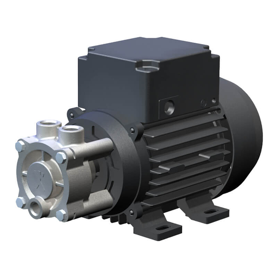
Baureihen CY, CSY, LNY,
LSY, NPY, PY, Y, YS
Kleinkreiselpumpen mit Peripheralrad,
Gleitringdichtung und Metallgehäuse
Speck Pumpen Walter Speck GmbH & Co. KG
Regensburger Ring 6 – 8, 91154 Roth / Deutschland
Postfach 1453, 91142 Roth / Deutschland
Tel.:
+49 (0) 9171 809 0
Fax:
+49 (0) 9171 809 10
E-Mail:
info@speck-pumps.de
Internet:
www.speck-pumps.de
Ausgabe:
ersetzt Ausgabe:
05/2011
11/2010
Dok./ Art.-Nr.:
1096.0821
Werbung
Inhaltsverzeichnis

Verwandte Anleitungen für Speck-Pumpen CY Serie


Inhaltszusammenfassung für Speck-Pumpen CY Serie
- Seite 1 Betriebsanleitung Baureihen CY, CSY, LNY, LSY, NPY, PY, Y, YS Kleinkreiselpumpen mit Peripheralrad, Gleitringdichtung und Metallgehäuse Originalbetriebsanleitung Speck Pumpen Walter Speck GmbH & Co. KG Regensburger Ring 6 – 8, 91154 Roth / Deutschland Postfach 1453, 91142 Roth / Deutschland Dokumentation Tel.: +49 (0) 9171 809 0...
-
Seite 2: Inhaltsverzeichnis
Betriebsanleitung Inhaltsverzeichnis Wichtige grundlegende Informationen ......4 Betrieb ................14 Zielgruppen ............. 5 Inbetriebnahme vorbereiten ........14 Mitgeltende Dokumente .......... 5 6.1.1 Stillstandzeit prüfen ..........14 6.1.2 Füllen und Entlüften ..........14 Warnhinweise und Symbole ........6 In Betrieb nehmen ..........14 Fachbegriffe ............ - Seite 3 Betriebsanleitung 10.1.6 Kennlinien Y/YS-2951 .......... 35 10.1.7 Maß- und Schnittzeichnung Y/YS-2051 ....36 10.1.8 Kennlinien Y/YS-2051 .......... 37 10.1.9 Maß und Schnittzeichnung NPY-2051 selbstansaugend ..........38 10.1.10 Kennlinien NPY-2051 selbstansaugend ..39 10.1.11 Maß- und Schnittzeichnung NPY-2051 ... 40 10.1.12 Kennlinien NPY-2051 ........
-
Seite 4: Wichtige Grundlegende Informationen
Betriebsanleitung Wichtige grundlegende Informationen Diese Betriebsanleitung ist Bestandteil der Technischen Dokumentation der Anlage gemäß EG-Maschinenrichtlinie. Die vorliegende Betriebsanleitung entspricht der Maschinenrichtlinie 2006/42/EG des Europäischen Parlaments und des Rates zur Angleichung der Rechts- und Verwaltungsvorschriften der Mitgliedstaaten für Maschinen, Anhang I, Punkt 1.7.4 Die vorliegende Betriebsanleitung ist an den Werksverantwortli- Lieferumfang chen gerichtet, der sie dem für die Aufstellung, den Anschluss,... -
Seite 5: Zielgruppen
Betriebsanleitung 1.1 Zielgruppen Zielgruppe Aufgabe Betreiber ► Diese Anleitung am Einsatzort der Anlage verfügbar halten, auch für spätere Verwendung. ► Mitarbeiter zum Lesen und Beachten dieser Anleitung und der mitgeltenden Dokumente anhalten, insbesondere der Sicherheits- und Warnhinweise. ► Zusätzliche anlagenbezogene Bestimmungen und Vor- schriften beachten. -
Seite 6: Warnhinweise Und Symbole
Betriebsanleitung 1.3 Warnhinweise und Symbole Warnhinweis Gefahrenstufe Folgen bei Nichtbeachtung unmittelbar drohende Gefahr Tod, schwere Körperverletzung GEFAHR mögliche drohende Gefahr Tod, schwere Körperverletzung WARNUNG mögliche gefährliche Situation Leichte Körperverletzung VORSICHT mögliche gefährliche Situation Sachschaden VORSICHT Tab. 3 Warnhinweise und Folgen bei Nichtbeachtung Symbol Bedeutung Sicherheitszeichen... -
Seite 7: Sicherheit
Betriebsanleitung Sicherheit Der Hersteller haftet nicht für Schäden aufgrund Nichtbe- 2.3 Allgemeine Sicherheitshinweise achtung der Gesamtdokumentation. Folgende Bestimmungen vor Ausführung sämtlicher Tätig- 2.1 Bestimmungsgemäße Verwendung keiten beachten. • Alle Hinweise der Betriebsanleitung beachten. 2.3.1 Produktsicherheit • Alle Sicherheitshinweise beachten. Die Pumpe / das Aggregat ist nach dem Stand der Technik und •... -
Seite 8: Sicherheitseinrichtungen
Betriebsanleitung 2.3.2.3 Sicherheitseinrichtungen 2.5 Spezielle Gefahren • Folgende Sicherheitseinrichtungen vorsehen und deren 2.5.1 Explosionsgefährdeter Bereich Funktion sicherstellen: • ( ATEX-Zusatzanleitung) − für heiße, kalte und sich bewegende Teile: bauseitiger Berührungsschutz der Pumpe / des Aggregates 2.5.2 Gefährliche Fördermedien − bei möglicher elektrostatischer Aufladung: entspre- chende Erdung vorsehen •... -
Seite 9: Aufbau Und Funktion
Betriebsanleitung Aufbau und Funktion 3.1.3 Pumpentyp-Kennzeichnung 3.1 Kennzeichnung LNY- .0000 3.1.1 Typenschild .0000 CSY- .0000 1 Pumpentype (Beispiele) 2 Pumpengröße 3 Stufenzahl 4 Zählnummer Tab. 6 Pumpentyp-Kennzeichnung (Beispiele) 1 Pumpentyp 2 Werksnummer 3 Förderhöhe 4 Leistungsbedarf 5 Förderstrom 6 Drehzahl Abb. -
Seite 10: Allgemeine Beschreibung
Betriebsanleitung 3.2 Allgemeine Beschreibung 3.3 Aufbau und Wirkungsweise Pumpen der Typenreihe CY, CSY, NPY, LNY, LSY, PY, Y und YS sind einstufige, horizontale Kreiselpumpen in Blockbauweise. Die verlängerte Motorwelle ist bei der Blockbauweise die Pum- penwelle, auf der Laufrad und Gleitringdichtung montiert sind. Das Laufrad ist als Peripheralrad ausgeführt und schwimmend auf der Motorwelle angeordnet. -
Seite 11: Transport, Lagerung Und Entsorgung
Betriebsanleitung Transport, Lagerung und 4.2 Lagern Entsorgung Neue Aggregate sind werksseitig so vorbereitet, dass ohne weiteren Aufwand, eine Zwischenlagerung möglich ist. Wird ein bereits betriebenes Aggregat eingelagert, so ist diese 4.1 Transportieren gemäß Punkt 4.3 vorzubereiten. Gewichtsangaben ( Anhang, Seite 30 ff.) VORSICHT 4.1.1 Auspacken und Lieferzustand prüfen... -
Seite 12: Aufstellung Und Anschluss
Betriebsanleitung Aufstellung und Anschluss Für Aggregate im explosionsgefährdeten Bereich 5.3 Leitungen planen ( ATEX-Zusatzanleitung) 5.3.1 Abstützungen und Anschlüsse auslegen VORSICHT VORSICHT Sachschaden durch Verunreinigungen! ► Transportsicherungen erst unmittelbar vor Aufstellung des Sachschaden durch zu hohe Kräfte und Drehmomente der Aggregates entfernen. -
Seite 13: Sicherheits- Und Kontrolleinrichtungen
Betriebsanleitung 5.3.5 Sicherheits- und Kontrolleinrichtungen 5.4.4 Spannungsfreier Rohrleitungsanschluss Für einen störungsfreien Betreib des Aggregates empfehlen Rohrleitung gemäß VDMA Richtlinie 24277 wir die folgenden Punkte zu beachten: Spannungsarmer Rohrleitungsanschluss ausführen. 5.3.5.1 Verschmutzung vermeiden 5.5 Elektrisch anschließen Filter in die Saugleitung einbauen (Siebquerschnitt = 3 x DN , Maschenweite 0,1 mm). -
Seite 14: Betrieb
Betriebsanleitung Betrieb VORSICHT Für Aggregate im explosionsgefährdeten Bereich ( ATEX Zusatzanleitung) Sachschaden durch geschlossene Druckleitung! ► Aggregat nicht gegen geschlossene druckseitige Armatur 6.1 Inbetriebnahme vorbereiten betreiben. 6.1.1 Stillstandzeit prüfen ► Mindestförderstrom beachten ( Betriebsgrenzwerte, Seite 25). ► Bei Stillstandzeit > 1 Jahr: Hersteller kontaktieren und Maßnahmen erfragen. -
Seite 15: Außer Betrieb Nehmen
Betriebsanleitung 6.3 Außer Betrieb nehmen WARNUNG Verletzungsgefahr durch heiße Pumpenteile oder heiße Fördermedien! ► Bei allen Arbeiten am Aggregat Schutzausrüstung verwen- den. ► Austretendes Fördermedium sicher auffangen und umwelt- gerecht entsorgen. Bei Betriebsunterbrechungen folgende Maßnahmen durchfüh- ren: Pumpe wird Maßnahme in Betriebsbe- ►... -
Seite 16: Wartung Und Instandhaltung
Betriebsanleitung Wartung und Instandhaltung 7.2 Demontieren GEFAHR Für Pumpen / Aggregate im explosionsgefährdeten Bereich ( ATEX Zusatzanleitung) Verletzungsgefahr durch laufendes Aggregat! Für Montagen und Reparaturen stehen geschulte Kunden- ► Laufendes Aggregat nicht berühren. dienst-Monteure zur Verfügung. Bei Anforderung einen ►... -
Seite 17: Ersatzteile
Betriebsanleitung 7.2.2 Ersatzteile 7.2.6 Demontage Y-/YS-2951 und Y-/YS-2051 Ersatzteile erhalten Sie über Ihren Zulieferer oder den Schnittzeichnung Y-/YS-2951 und Y-/YS-2051 Hersteller. ( Seite 34 ff.) Für Ersatzteilbestellungen werden folgende Angaben benötigt. Pumpenaggregat ist aus der Anlage ausgebaut und befin- ... -
Seite 18: Demontage Py-2071
Betriebsanleitung Gleitringdichtung und Gehäuse für Wellendichtung / bzw. 7.2.8 Demontage PY-2071 Gehäuse demontieren Schnittzeichnung PY-2071 ( Seite 42) − Sicherungsring (932) und Kegelhülse (504) von der Motorwelle abziehen. Pumpenaggregat ist aus der Anlage ausgebaut und befin- det sich an einem sauberen und ebenen Montageplatz. −... -
Seite 19: Montage
Betriebsanleitung 7.3.3 Montage Y-2041 7.3 Montage Schnittzeichnung Y-2041 ( Seite 32) 7.3.1 Montagevorbereitung Gleitringdichtung – stationäre Einheit montieren VORSICHT − Nebendichtung der stationären Einheit mit Gleitmittel (Alkohol, Wasser) anfeuchten. Nicht fachgerechte Montage führt zu Beschädigung des − Stationäre Einheit (047) von Hand in das Gehäuse für Aggregates! Wellendichtung (441) eindrücken. -
Seite 20: Montage Npy-2051
Betriebsanleitung Y-/ YS-2951 7.3.6 Montage PY-2071 − Sechskantschrauben (901) in das Gehäuse einführen Schnittzeichnung PY-2071 ( Seite 42) und mit dem Gehäuse für Wellendichtung verschrau- Gleitringdichtung – stationäre Einheit montieren ben. − Nebendichtung der stationären Einheit (047) mit Gleit- ... -
Seite 21: Montage Y-5081 / Cy-5091
Betriebsanleitung Gehäuse bzw. Gehäusedeckel montieren 7.3.9 Montage Y-6091 Y-4081 Schnittzeichnung Y-6091( Seite 54) − O-Ring (412) im Gehäuse für Wellendichtung (441) Materialausführung: Messing/ Edelstahl zentrieren. − Gehäuse (101) am Gehäuse für Wellendichtung einfe- Gleitringdichtung – stationäre Einheit montieren dern und ausrichten. -
Seite 22: Störungsbehebung
Betriebsanleitung Störungsbehebung GEFAHR Verletzungsgefahr durch laufendes Aggregat! ► Laufendes Aggregat nicht berühren. ► Keine Arbeiten am laufenden Aggregat durchführen. ► Bei allen Montage- und Wartungsarbeiten Motor spannungsfrei schalten und gegen Wiedereinschalten sichern. GEFAHR DURCH STROMSCHLAG Lebensgefahr durch Stromschlag! ► Alle Arbeiten am elektrischen Anschluss nur durch Fachkraft ausführen lassen. ►... - Seite 23 Betriebsanleitung Störung Ursache Beseitigung Motorschutz spricht an Motor überlastet ► Spezifizierter Betriebspunkt wird nicht einge- halten Motor oder Pumpe blockiert ► Motor/Pumpe prüfen, Motor/Pumpe zerle- gen, Ursache beseitigen Kurzschluss in der Motorwicklung ► Motorwicklung prüfen Motorschutzschalter falsch eingestellt/defekt ► Einstellung prüfen/Motorschutzschalter ersetzen Leistungsaufnahme Motor Verunreinigungen/Verkalkungen in der Pumpe...
- Seite 24 Betriebsanleitung Störung Ursache Beseitigung Ungewöhnliche Geräu- Kavitation der Pumpe ► Temperatur des Fördermediums reduzieren, sche NPSH prüfen Dampfanteil im Saugstrom zu hoch ► Temperatur des Fördermediums reduzieren, NPSH prüfen Saugseitige Armatur geschlossen ► Saugseitige Armatur öffnen Unterdruck in der Saugleitung ►...
-
Seite 25: Technische Daten
Betriebsanleitung Technische Daten 9.1 Betriebsgrenzwerte − Förderhöhe − Fördermedium − Drehzahl − Förderstrom − Schalthäufigkeit LNY/LSY-2841 Y/YS-2051 max. Förderhöhe max. Förderhöhe LNY-2841 Y-2051 LSY-2841 YS-2051 Fördermedium Wasser Fördermedium Wasser Temperatur [°C] Temperatur [°C] max. max. Dichte [kg/m³] Fördermedium Öl max. 1000 Temperatur [°C]... - Seite 26 Betriebsanleitung NPY-2051 CY-4081 max. Förderhöhe max. Förderhöhe NPY-2051 / Q30 CY-4081/ Q45 NPY-2051 / Q27 CY-4081/ Q60 Fördermedium Wasser Fördermedium Wasser Temperatur [°C] Temperatur [°C] max. max. Fördermedium Öl Fördermedium Öl Temperatur [°C] Temperatur [°C] max. max. Dichte [kg/m³] Dichte [kg/m³] max.
-
Seite 27: Fördermedien
Betriebsanleitung 9.2 Allgemeine Technische Daten CY-5091 Die nachfolgenden Angaben beziehen sich auf Standardwerte. Abweichende Daten sind beim Hersteller zu erfragen. max. Förderhöhe 9.2.1 Gewicht Fördermedium Wasser Maßzeichnungen Seite 30 ff. Temperatur [°C] 9.2.2 Schallpegel max. Fördermedium Öl 1-m-Messflächenschalldruckpegel L [dB (A)]* Temperatur [°C] max. -
Seite 28: Umgebungsbedingungen
Betriebsanleitung 9.2.9.3 Edelstahlschrauben 9.2.7 Umgebungsbedingungen ► Die Schrauben mit einem Drehmomentschlüssel anziehen. Einsatz unter anderen Umgebungsbedingungen mit dem Hersteller abstimmen. Nachfolgende Werte gelten für neue Edelstahlschrauben und Muttern (A2, A4-70), sowie in Edelstahlteilen Temperatur Relative Luftfeuchtigkeit Aufstellungs- [°C] Höhe über NN Größe Güteklasse... -
Seite 29: Anhang
Betriebsanleitung 10 Anhang Dem Anhang sind zu entnehmen: • Aggregatmaße (Maßzeichnungen) • Ersatzteilbezeichnung und Position (Schnittzeichnungen) • Kennlinien der Pumpentypen • Unbedenklichkeitsbescheinigung • EG - Konformitätserklärung 05/2011 1096.0821 | Baureihen CY, CSY, LNY, LSY, NPY, PY, Y, YS... -
Seite 30: Maß- Und Schnittzeichnungen, Kennlinien
Betriebsanleitung 10.1 Maß- und Schnittzeichnungen, Kennlinien 10.1.1 Maß- und Schnittzeichnung LNY/LSY-2841 Abb. 6 Maßzeichnung LNY/LSY-2841 Type Bau- Pha- 50 Hz 60 Hz Anschlüsse Gewicht Maße größe [1/min] [kW] [HP] [1/min] [kW] [HP] [kg] [lbs] LNY-2841 top/top 1~/3~ 2800 0,12 0.16 3400 0,12 0.16... -
Seite 31: Kennlinien Lny/Lsy-2841
Betriebsanleitung 10.1.2 Kennlinien LNY/LSY-2841 Abb. 8 Kennlinien LNY/LSY-2841 Prüfbedingungen: Die Kennlinien gelten für die Förderung von Wasser mit einer Temperatur von 20 °C bei Nenndrehzahl. Die Toleranz von Förderhöhe und Förderstrom beträgt ± 10 %, die des Leistungsbedarfs + 10 %. Bei abweichenden Eigenschaften des Fördermediums ändern sich die Kennlinien. -
Seite 32: Maß- Und Schnittzeichnung Y-2041
Betriebsanleitung 10.1.3 Maß- und Schnittzeichnung Y-2041 Abb. 9 Maßzeichnung Y-2041 Type Bau- Pha- 50 Hz 60 Hz Anschlüsse Gewicht größe [1/min] [kW] [HP] [1/min] [kW] [HP] [kg] [lbs] Y-2041 1~/3~ 2800 0,12 0.16 3400 0,12 0.16 G 1/4 G 1/4 Tab. -
Seite 33: Kennlinien Y-2041
Betriebsanleitung 10.1.4 Kennlinien Y-2041 Abb. 11 Kennlinien Y-2041 Prüfbedingungen: Die Kennlinien gelten für die Förderung von Wasser mit einer Temperatur von 20 °C bei Nenndrehzahl. Die Toleranz von Förderhöhe und Förderstrom beträgt ± 10 %, die des Leistungsbedarfs + 10 %. Bei abweichenden Eigenschaften des Fördermediums ändern sich die Kennlinien. -
Seite 34: Maß- Und Schnittzeichnung Y/Ys-2951
Betriebsanleitung 10.1.5 Maß- und Schnittzeichnung Y/YS-2951 Abb. 12 Maßzeichnung Y/YS-2951 Type Bau- Pha- 50 Hz 60 Hz Anschlüsse Gewicht größe [1/min] [kW] [HP] [1/min] [kW] [HP] [kg] [lbs] Y-2951 / 1~/3~ 2800 0,12 0.16 3400 0,12 0.16 G 1/4 G 1/4 YS-2951 1~/3~ 2800... -
Seite 35: Kennlinien Y/Ys-2951
Betriebsanleitung 10.1.6 Kennlinien Y/YS-2951 Abb. 14 Kennlinien Y/YS-2951 Prüfbedingungen: Die Kennlinien gelten für die Förderung von Wasser mit einer Temperatur von 20 °C bei Nenndrehzahl. Die Toleranz von Förderhöhe und Förderstrom beträgt ± 10 %, die des Leistungsbedarfs + 10 %. Bei abweichenden Eigenschaften des Fördermediums ändern sich die Kennlinien. -
Seite 36: Maß- Und Schnittzeichnung Y/Ys-2051
Betriebsanleitung 10.1.7 Maß- und Schnittzeichnung Y/YS-2051 Abb. 15 Maßzeichnung Y/YS-2051 Type Bau- Anschlüsse Gewicht 50 Hz 60 Hz größe [1/min] [kW] [HP] [1/min] [kW] [HP] [kg] [lbs] Y-2051 top/top 2800 0,35 0.47 3400 0,35 0.47 G 1/2 G 1/2 G 1/8 13.7 YS-2051 top/top 2800... -
Seite 37: Kennlinien Y/Ys-2051
Betriebsanleitung 10.1.8 Kennlinien Y/YS-2051 Abb. 17 Kennlinien Y/YS-2051 Prüfbedingungen: Die Kennlinien gelten für die Förderung von Wasser mit einer Temperatur von 20 °C bei Nenndrehzahl. Die Toleranz von Förderhöhe und Förderstrom beträgt ± 10 %, die des Leistungsbedarfs + 10 %. Bei abweichenden Eigenschaften des Fördermediums ändern sich die Kennlinien. -
Seite 38: Maß Und Schnittzeichnung Npy-2051 Selbstansaugend
Betriebsanleitung 10.1.9 Maß und Schnittzeichnung NPY-2051 selbstansaugend Abb. 18 Maßzeichnung NPY-2051 selbstansaugend Type Bau- 50 Hz 60 Hz Anschlüsse Gewicht größe [1/min] [kW] [HP] [1/min] [kW] [HP] [kg] [lbs] NPY-2051 1~/3~ 2800 0,25 0.34 3400 0,25 0.34 G 3/4 G 3/4 2800 0,35 0.47... -
Seite 39: Kennlinien Npy-2051 Selbstansaugend
Betriebsanleitung 10.1.10 Kennlinien NPY-2051 selbstansaugend Abb. 20 Kennlinien NPY-2051 selbstansaugend Prüfbedingungen: Die Kennlinien gelten für die Förderung von Wasser mit einer Temperatur von 20 °C bei Nenndrehzahl. Die Toleranz von Förderhöhe und Förderstrom beträgt ± 10 %, die des Leistungsbedarfs + 10 %. Bei abweichenden Eigenschaften des Fördermediums ändern sich die Kennlinien. -
Seite 40: Maß- Und Schnittzeichnung Npy-2051
Betriebsanleitung 10.1.11 Maß- und Schnittzeichnung NPY-2051 Abb. 21 Maßzeichnung NPY-2051 Type Bau- 50 Hz 60 Hz Anschlüsse Gewicht größe [1/min] [kW] [HP] [1/min] [kW] [HP] [kg] [lbs] NPY-2051 1~/3~ 2800 0,25 0.34 3400 0,25 0.34 G 3/8 G 3/8 G 1/8 12.3 top/top oder... -
Seite 41: Kennlinien Npy-2051
Betriebsanleitung 10.1.12 Kennlinien NPY-2051 Abb. 23 Kennlinien NPY-2051 Prüfbedingungen: Die Kennlinien gelten für die Förderung von Wasser mit einer Temperatur von 20 °C bei Nenndrehzahl. Die Toleranz von Förderhöhe und Förderstrom beträgt ± 10 %, die des Leistungsbedarfs + 10 %. Bei abweichenden Eigenschaften des Fördermediums ändern sich die Kennlinien. -
Seite 42: Maß- Und Schnittzeichnung Py-2071
Betriebsanleitung 10.1.13 Maß- und Schnittzeichnung PY-2071 Abb. 24 Maßzeichnung PY-2071 Type Bau- 50 Hz 60 Hz Anschlüsse Gewicht größe [1/min] [kW] [HP] [1/min] [kW] [HP] [kg] [lbs] PY-2071 1~/3~ 2800 0,25 0.34 3400 0,25 0.34 G 3/8 G 3/8 2800 0,35 0.47 3400... -
Seite 43: Kennlinien Py-2071
Betriebsanleitung 10.1.14 Kennlinien PY-2071 Abb. 26 Kennlinien PY-2071 Prüfbedingungen: Die Kennlinien gelten für die Förderung von Wasser mit einer Temperatur von 20 °C bei Nenndrehzahl. Die Toleranz von Förderhöhe und Förderstrom beträgt ± 10 %, die des Leistungsbedarfs + 10 %. Bei abweichenden Eigenschaften des Fördermediums ändern sich die Kennlinien. -
Seite 44: Maß- Und Schnittzeichnung Y-4081
Betriebsanleitung 10.1.15 Maß- und Schnittzeichnung Y-4081 Abb. 27 Maßzeichnung Y-4081 Type Bau- 50 Hz 60 Hz Anschlüsse Gewicht größe [1/min] [kW] [HP] [1/min] [kW] [HP] [kg] [lbs] Y-4081 top/top 2800 0,75 1.01 3400 0,75 1.01 2800 1,00 1.34 3400 1,00 1.34 G 3/4 G 3/4... -
Seite 45: Kennlinien Y-4081
Betriebsanleitung 10.1.16 Kennlinien Y-4081 Abb. 29 Kennlinien Y-4081 Prüfbedingungen: Die Kennlinien gelten für die Förderung von Wasser mit einer Temperatur von 20 °C bei Nenndrehzahl. Die Toleranz von Förderhöhe und Förderstrom beträgt ± 10 %, die des Leistungsbedarfs + 10 %. Bei abweichenden Eigenschaften des Fördermediums ändern sich die Kennlinien. -
Seite 46: Maß- Und Schnittzeichnung Cy-4081
Betriebsanleitung 10.1.17 Maß- und Schnittzeichnung CY-4081 Abb. 30 Maßzeichnung CY-4081 Type Bau- 50 Hz 60 Hz Anschlüsse Gewicht größe [1/min] [kW] [HP] [1/min] [kW] [HP] [kg] [lbs] CY-4081 top/top 2800 0,55 0.74 3400 0,55 0.74 2800 0,75 1.01 3400 0,75 1.01 G 3/4 G 3/4... -
Seite 47: Kennlinien Cy-4081
Betriebsanleitung 10.1.18 Kennlinien CY-4081 Abb. 32 Kennlinien CY-4081 Prüfbedingungen: Die Kennlinien gelten für die Förderung von Wasser mit einer Temperatur von 20 °C bei Nenndrehzahl. Die Toleranz von Förderhöhe und Förderstrom beträgt ± 10 %, die des Leistungsbedarfs + 10 %. Bei abweichenden Eigenschaften des Fördermediums ändern sich die Kennlinien. -
Seite 48: Maß- Und Schnittzeichnung Csy-4081
Betriebsanleitung 10.1.19 Maß- und Schnittzeichnung CSY-4081 Abb. 33 Maßzeichnung CSY-4081 Type Bau- 50 Hz 60 Hz Anschlüsse Gewicht größe [1/min] [kW] [HP] [1/min] [kW] [HP] [kg] [lbs] CSY-4081 2800 0,75 1.01 3400 0,75 1.01 G 3/4 G 3/4 G 1/8 10,5 23.2 2800... -
Seite 49: Kennlinien Csy-4081
Betriebsanleitung 10.1.20 Kennlinien CSY-4081 Abb. 35 Kennlinien CSY-4081 Prüfbedingungen: Die Kennlinien gelten für die Förderung von Wasser mit einer Temperatur von 20 °C bei Nenndrehzahl. Die Toleranz von Förderhöhe und Förderstrom beträgt ± 10 %, die des Leistungsbedarfs + 10 %. Bei abweichenden Eigenschaften des Fördermediums ändern sich die Kennlinien. -
Seite 50: Maß-Und Schnittzeichnung Y-5081
Betriebsanleitung 10.1.21 Maß-und Schnittzeichnung Y-5081 Abb. 36 Maßzeichnung Y-5081 Type Bau- 50 Hz 60 Hz Anschlüsse Gewicht größe [1/min] [kW] [HP] [1/min] [kW] [HP] [kg] [lbs] Y-5081 2800 3400 SAE 1 SAE 1 G 1/4 16,2 35.7 Tab. 54 Daten Y-5081 Gewicht abhängig von Baugröße, Leistung, Werkstoffen und 3~ Drehstrommotor Ausführung... -
Seite 51: Kennlinien Y-5081
Betriebsanleitung 10.1.22 Kennlinien Y-5081 Abb. 38 Kennlinien Y-5081 Prüfbedingungen: Die Kennlinien gelten für die Förderung von Wasser mit einer Temperatur von 20 °C bei Nenndrehzahl. Die Toleranz von Förderhöhe und Förderstrom beträgt ± 10 %, die des Leistungsbedarfs + 10 %. Bei abweichenden Eigenschaften des Fördermediums ändern sich die Kennlinien. -
Seite 52: Maß- Und Schnittzeichnung Cy-5091
Betriebsanleitung 10.1.23 Maß- und Schnittzeichnung CY-5091 Abb. 39 Maßzeichnung CY-5091 Type Bau- 50 Hz 60 Hz Anschlüsse Gewicht größe [1/min] [kW] [HP] [1/min] [kW] [HP] [kg] [lbs] CY-5091 2800 3400 SAE 1 SAE 1 G 1/4 16,4 36.2 2800 3400 Tab. -
Seite 53: Kennlinien Cy-5091
Betriebsanleitung 10.1.24 Kennlinien CY-5091 Abb. 41 Kennlinien CY-5091 Prüfbedingungen: Die Kennlinien gelten für die Förderung von Wasser mit einer Temperatur von 20 °C bei Nenndrehzahl. Die Toleranz von Förderhöhe und Förderstrom beträgt ± 10 %, die des Leistungsbedarfs + 10 %. Bei abweichenden Eigenschaften des Fördermediums ändern sich die Kennlinien. -
Seite 54: Maß- Und Schnittzeichnungen Y-6091
Betriebsanleitung 10.1.25 Maß- und Schnittzeichnungen Y-6091 Abb. 42 Maßzeichnung Y-6091 Type Bau- 50 Hz 60 Hz Anschlüsse Gewicht größe [1/min] [kW] [HP] [1/min] [kW] [HP] [kg] [lbs] Y-6091 2800 3400 abhängig von Werkstoff- 2800 3400 G 1/4 30,6 67.5 ausführung 2800 3400 Type... - Seite 55 Betriebsanleitung Abb. 43 Schnittzeichnung Y-6091 (Messing) Abb. 44 Schnittzeichnung Y-6091 (Edelstahl) Bezeichnung Bezeichnung Gleitringdichtung Gleitringdichtung Gehäuse Gehäuse Laufrad Laufrad 411* Dichtring O-Ring O-Ring Gehäuse für Wellendichtung Gehäuse für Wellendichtung Abstandsring Spritzring Spritzring 550/.1 Scheibe Stift 6-kt. Schraube Motor 903* Verschlussschraube 901-.2 6-kt.
-
Seite 56: Kennlinien Y-6091
Betriebsanleitung 10.1.26 Kennlinien Y-6091 Abb. 45 Kennlinien Y-6091 Prüfbedingungen: Die Kennlinien gelten für die Förderung von Wasser mit einer Temperatur von 20 °C bei Nenndrehzahl. Die Toleranz von Förderhöhe und Förderstrom beträgt ± 10 %, die des Leistungsbedarfs + 10 %. Bei abweichenden Eigenschaften des Fördermediums ändern sich die Kennlinien. -
Seite 57: Unbedenklichkeitserklärung
Betriebsanleitung 10.2 Unbedenklichkeitserklärung Bitte kopieren und mit der Pumpe / dem Pumpenaggregat einsenden. Unbedenklichkeitserklärung Die von uns, dem Unterzeichner / der Unterzeichnerin, zusammen mit dieser Unbedenklichkeitsbescheinigung in Inspektions- / Reparaturauftrag gegebene bzw. zurückgesendete Pumpe / Pumpenaggregat und deren Zubehör, Bezeichnung: Typ: Seriennummer:... -
Seite 58: Eg - Konformitätserklärung
Betriebsanleitung 10.3 EG – Konformitätserklärung 1096.0821 | Baureihen CY, CSY, LNY, LSY, NPY, PY, Y, YS 05/2011... - Seite 59 Operating Instructions CY, CSY, LNY, LSY, NPY, PY, Y, YS Series Small Centrifugal Pumps with Peripheral Impeller, Mechanical Seal and Metal Casing English translation of the original operating Speck Pumpen Walter Speck GmbH & Co. KG instructions Regensburger Ring 6 – 8, 91154 Roth / Germany PO Box 1453, 91142 Roth / Germany Documentation Phone:...
- Seite 60 Operating Instructions Index Important basic information ..........4 Preparations for commissioning ......14 6.1.1 Checking shut-down period ........14 Target groups ............5 6.1.2 Filling and venting ..........14 Applicable documents ..........5 Commissioning ............14 6.2.1 Switch-on .............. 14 Warnings and symbols ..........
- Seite 61 Operating Instructions 10.1.8 Characteristic curves Y-/YS-2051 ......37 10.1.9 Dimension & cross-sectional drawings NPY-2051, self-priming ............38 10.1.10 Characteristic curves NPY-2051, self-priming . 39 10.1.11 Dimension & cross-sectional drawing NPY-2051 40 10.1.12 Characteristic curves NPY-2051 ..... 41 10.1.13 Dimension & cross-sectional drawing PY-2071 42 10.1.14 Characteristic curves PY-2071 ......
-
Seite 62: Important Basic Information
Operating Instructions Important basic information These operating instructions form part of the technical documentation of the system in accordance with the EC machinery directive. These operating instructions comply with machinery directive 2006/42/EC of the European Parliament and the Council on the approxi- mation of the laws, regulations and administrative provisions of the Member States relating to machinery, Appendix I, Paragraph 1.7.4. -
Seite 63: Target Groups
Operating Instructions 1.1 Target groups Target group Task ► Operator Keep these instructions available at the location of the system, also for later consultation. ► Advise staff to read and observe these instructions and the provided documents, particularly the safety precautions and warnings. -
Seite 64: Warnings And Symbols
Operating Instructions 1.3 Warnings and symbols Warning Security level Consequences of non-observance imminently hazardous situation death, severe personal injuries DANGER potentially hazardous situation death, severe personal injuries WARNING potentially dangerous situation minor personal injuries CAUTION potentially dangerous situation material damage CAUTION Tab. -
Seite 65: Intended Use
Operating Instructions Safety 2.3 General safety instructions The manufacturer does not accept liability for damage resulting from non-observance of the overall documenta- tion. The following provisions must be observed prior to execut- ing any works. 2.1 Intended use 2.3.1 Product safety •... -
Seite 66: Safety Devices
Operating Instructions 2.3.2.3 Safety devices 2.5 Special risks • Provide for the following safety devices and ensure their 2.5.1 Potentially explosive area proper functioning: − • ( ATEX additional instructions) for hot, cold and moving parts: on-site protection against contact with the pump/aggregate 2.5.2 Dangerous media to be pumped −... -
Seite 67: Design And Functioning
Operating Instructions 3.1.3 Pump type code Design and functioning 3.1 Marking LNY- .0000 3.1.1 Nameplate .0000 CSY- .0000 1 Pump type (examples) 2 Pump size 3 Number of stages 4 Counting number Tab. 6 Pump type code (examples) 1 Pump type 2 Plant number 3 Total head 4 Power requirements... -
Seite 68: General Description
Operating Instructions 3.2 General description 3.3 Design and functional principle Pumps of the CY, CSY, NPY, LNY, LSY, PY, Y and YS series are single-stage, horizontal centrifugal pumps in close coupled version. The extended motor shaft of close coupled versions simultaneouly serves as pump shaft, on which the impeller and the mechanical seal is installed. -
Seite 69: Transport, Storage And Disposal
Operating Instructions 4.2 Storage Transport, storage and New aggregates have been prepared by the factory in a way, disposal which allows for intermediate storage without the need of any further measures. 4.1 Transport For storing aggregates which have already been in use, the preparations specified in Paragraph 4.3 must be made. -
Seite 70: Set-Up And Connection
Operating Instructions Set-up and connection 5.3 Planning pipe system For aggregates in potentially explosive areas ( ATEX additional instructions) 5.3.1 Dimensioning supports and connections CAUTION CAUTION Risk of material damage caused by contamination! ► Risk of material damage if the pipes apply excessive forces Do not remove transport locks until immediately before and torques to the aggregate! setting up the aggregate. -
Seite 71: Electrical Connection
Operating Instructions 5.3.5 Safety and control devices 5.5 Electrical connection Please observe the following recommendations for a trou- RISK OF ELECTRIC SHOCK ble-free aggregate operation. Risk of death from electric shock! 5.3.5.1 Avoiding contamination ► Any electrical works must be carried out by qualified electri- Install a filter in the suction pipe cians only. -
Seite 72: Preparations For Commissioning
Operating Instructions Operation CAUTION For aggregates in potentially explosive areas ( ATEX additional instructions) Risk of material damage caused by a closed pressure pipe! ► 6.1 Preparations for commissioning Do not operate the aggregate when the pressure-side fitting is closed. 6.1.1 Checking shut-down period ►... - Seite 73 Operating Instructions 6.3 Decommissioning WARNING Risk of injuries caused by hot pump parts or hot media to be pumped! ► Use protective equipment when carrying out any works on the aggregate. ► Reliably collect escaping media to be pumped and dispose of in an environmentally-friendly way.
-
Seite 74: Maintenance And Servicing
Operating Instructions 7.2 Disassembly Maintenance and servicing DANGER For pumps/aggregates in potentially explosive areas ( ATEX additional instructions) Risk of injuries caused by running aggregate! ► A qualified service team provides support for assembly and Do not touch the running aggregate. repair works. -
Seite 75: Spare Parts
Operating Instructions 7.2.2 Spare parts 7.2.6 Disassembly of Y-/YS-2951 and Y-/YS- 2051 Spare parts are available from your supplier or the manu- facturer. Cross-sectional drawing Y-/YS-2951 and Y-/YS-2051 ( page 34 et seq.) The following data are required for spare part orders. ... - Seite 76 Operating Instructions 7.2.8 Disassembly of PY-2071 Disassembly of mechanical seal and shaft sealing casing respectively casing Cross-sectional drawing PY-2071 ( page 42) − Pull the locking ring (932) and the conical sleeve (504) off the motor shaft. The pump aggregate has been removed from the system −...
-
Seite 77: Preparations For Assembly
Operating Instructions 7.3.3 Assembly of Y-2041 7.3 Assembly Cross-sectional drawing Y-2041 ( page 32) 7.3.1 Preparations for assembly Installation of mechanical seal, stationary unit CAUTION − Moisten the auxiliary seal of the stationary unit of the mechanical seal (047) with lubricant (alcohol, water). Improper assembly results in aggregate damage! −... - Seite 78 Operating Instructions Installation of suction casing Y-/YS-2951 − − Centre the O-ring (412) on the discharge casing. Insert hexagon head screws (901) into the casing and − Force the suction casing into the discharge casing fasten it to the shaft sealing casing. (101) and adjust.
- Seite 79 Operating Instructions Installation of mechanical seal, rotating unit Installation of impeller / setting of gap size − − Moisten the auxiliary seal of the rotating unit of the Insert the fitting key (940) into the motor shaft. − mechanical seal (047) with lubricant (grease containing Put two metal strips (0.2 mm thick) close to the motor PTFE).
- Seite 80 Operating Instructions Troubleshooting DANGER Risk of injuries caused by running aggregate! ► Do not touch the running aggregate. ► Do not carry out any works on the running aggregate. ► Prior to carrying out any assembly or maintenance works, de-energize the motor and protect it against restart. RISK OF ELECTRIC SHOCK Risk of death from electric shock! ►...
- Seite 81 Operating Instructions Defect Cause Rectification ► Motor protection triggered Motor overload The specified operating point has not been complied with ► Motor or pump blocked Check motor/pump, disassemble mo- tor/pump ► Short-circuit in the motor winding Check the motor winding ►...
- Seite 82 Operating Instructions Defect Cause Rectification ► Strange noise Pump cavitation Reduce the temperature of the medium to be pumped, check NPSH ► Excessive share of steam in the suction flow Reduce the temperature of the medium to be pumped, check NPSH ►...
-
Seite 83: Technical Data
Operating Instructions Technical data 9.1 Operating limits − Total head − Medium to be pumped − Speed − Flow rate − Switching frequency LNY-/LSY-2841 Y-/YS-2051 Max. total head Max. total head LNY-2841 Y-2051 LSY-2841 YS-2051 Medium to be pumped Water Medium to be pumped Water Temperature... - Seite 84 Operating Instructions NPY-2051 CY-4081 Max. total head Max. total head NPY-2051/Q30 CY-4081/ Q45 NPY-2051/Q27 CY-4081/ Q60 Medium to be pumped Water Medium to be pumped Water Temperature [°C] Temperature [°C] Max. Max. Medium to be pumped Medium to be pumped Temperature [°C] Temperature...
-
Seite 85: General Technical Data
Operating Instructions 9.2 General technical data CY-5091 The following data refer to standard values. For deviating data, please consult the manufacturer. Max. total head 9.2.1 Weight Medium to be pumped Water Dimension drawings, page 30 et seq. Temperature [°C] 9.2.2 Sound level Max. -
Seite 86: Ambient Conditions
Operating Instructions 9.2.9.3 Stainless steel screws 9.2.7 Ambient conditions ► Tighten the screws by means of a torque wrench. Operation under other ambient conditions has to be agreed with the manufacturer. The following values apply to new stainless steel screws and nuts (A2, A4-70) as well as in stainless steel casings. - Seite 87 Operating Instructions 10 Appendix The appendix contains: • Aggregate dimensions (dimension drawings) • Spare parts designation and position (cross-sectional drawings) • Characteristic curves of pump types • Certificate of conformity • EC declaration of conformity 05/2011 1096.0833 | CY, CSY, LNY, LSY, NPY, PY, Y, YS Series...
- Seite 88 Operating Instructions 10.1 Dimension and cross-sectional drawings, characteristic curves 10.1.1 Dimension & cross-sectional drawings LNY-/LSY-2841 Fig. 6 Dimension drawing of LNY-/LSY-2841 Type Size Phases 50 Hz 60 Hz Connections Weight Dimen- sions [1/min] [kW] [HP] [1/min] [kW] [HP] [kg] [lbs] LNY-2841 top/top 1~/3~ 2800...
- Seite 89 Operating Instructions 10.1.2 Characteristic curves LNY-/LSY-2841 Fig. 8 Characteristic curves of LNY-/LSY-2841 Test conditions: The characteristic curves apply to the delivery of water with a temperature of 20°C at nominal speed. Total head and flow rate have a tolerance range of ± 10 %, whereas the power requirement may deviate by + 10 %. Deviating properties of the media to be pumped affect the characteristic curves.
- Seite 90 Operating Instructions 10.1.3 Dimension & cross-sectional drawing Y-2041 Fig. 9 Dimension drawing of Y-2041 Type Size Phases 50 Hz 60 Hz Connections Weight [1/min] [kW] [HP] [1/min] [kW] [HP] [kg] [lbs] Y-2041 1~/3~ 2800 0.12 0.16 3400 0.12 0.16 G 1/4 G 1/4 Tab.
- Seite 91 Operating Instructions 10.1.4 Characteristic curves Y-2041 Fig. 11 Characteristic curves of Y-2041 Test conditions: The characteristic curves apply to the delivery of water with a temperature of 20°C at nominal speed. Total head and flow rate have a tolerance range of ± 10 %, whereas the power requirement may deviate by + 10 %. Deviating properties of the media to be pumped affect the characteristic curves.
- Seite 92 Operating Instructions 10.1.5 Dimension & cross-sectional drawing Y-/YS-2951 Fig. 12 Dimension drawing of Y-/YS-2951 Type Size Phases 50 Hz 60 Hz Connections Weight [1/min] [kW] [HP] [1/min] [kW] [HP] [kg] [lbs] Y-2951 / 1~/3~ 2800 0.12 0.16 3400 0.12 0.16 G 1/4 G 1/4 YS-2951...
- Seite 93 Operating Instructions 10.1.6 Characteristic curves Y-/YS-2951 Fig. 14 Characteristic curves of Y-/YS-2951 Test conditions: The characteristic curves apply to the delivery of water with a temperature of 20°C at nominal speed. Total head and flow rate have a tolerance range of ± 10 %, whereas the power requirement may deviate by + 10 %. Deviating properties of the media to be pumped affect the characteristic curves.
- Seite 94 Operating Instructions 10.1.7 Dimension & cross-sectional drawing Y-/YS-2051 Fig. 15 Dimension drawing of Y-/YS -2051 Type Size 50 Hz 60 Hz Connections Weight [1/min] [kW] [HP] [1/min] [kW] [HP] [kg] [lbs] Y-2051 top/top 2800 0.35 0.47 3400 0.35 0.47 G 1/2 G 1/2 G 1/8 13.7...
- Seite 95 Operating Instructions 10.1.8 Characteristic curves Y-/YS-2051 Fig. 17 Characteristic curves of Y-/YS-2051 Test conditions: The characteristic curves apply to the delivery of water with a temperature of 20°C at nominal speed. Total head and flow rate have a tolerance range of ± 10 %, whereas the power requirement may deviate by + 10 %. Deviating properties of the media to be pumped affect the characteristic curves.
- Seite 96 Operating Instructions 10.1.9 Dimension & cross-sectional drawings NPY-2051, self-priming Fig. 18 Dimension drawing of NPY-2051, self-priming Type Size 50 Hz 60 Hz Connections Weight [1/min] [kW] [HP] [1/min] [kW] [HP] [kg] [lbs] NPY-2051 1~/3~ 2800 0.25 0.34 3400 0.25 0.34 G 3/4 G 3/4 2800...
- Seite 97 Operating Instructions 10.1.10 Characteristic curves NPY-2051, self-priming Fig. 20 Characteristic curves of NPY-2051, self-priming Test conditions: The characteristic curves apply to the delivery of water with a temperature of 20°C at nominal speed. Total head and flow rate have a tolerance range of ±...
- Seite 98 Operating Instructions 10.1.11 Dimension & cross-sectional drawing NPY-2051 Fig. 21 Dimension drawing of NPY-2051 Type Size 50 Hz 60 Hz Connections Weight [1/min] [kW] [HP] [1/min] [kW] [HP] [kg] [lbs] NPY-2051 1~/3~ 2800 0.25 0.34 3400 0.25 0.34 G 3/8 G 3/8 G 1/8 12.3...
- Seite 99 Operating Instructions 10.1.12 Characteristic curves NPY-2051 Fig. 23 Characteristic curves of NPY-2051 Test conditions: The characteristic curves apply to the delivery of water with a temperature of 20°C at nominal speed. Total head and flow rate have a tolerance range of ± 10 %, whereas the power requirement may deviate by + 10 %. Deviating properties of the media to be pumped affect the characteristic curves.
- Seite 100 Operating Instructions 10.1.13 Dimension & cross-sectional drawing PY-2071 Fig. 24 Dimension drawing of PY-2071 Type Size 50 Hz 60 Hz Connections Weight [1/min] [kW] [HP] [1/min] [kW] [HP] [kg] [lbs] PY-2071 1~/3~ 2800 0.25 0.34 3400 0.25 0.34 G 3/8 G 3/8 2800 0.35...
- Seite 101 Operating Instructions 10.1.14 Characteristic curves PY-2071 Fig. 26 Characteristic curves of PY-2071 Test conditions: The characteristic curves apply to the delivery of water with a temperature of 20°C at nominal speed. Total head and flow rate have a tolerance range of ± 10 %, whereas the power requirement may deviate by + 10 %. Deviating properties of the media to be pumped affect the characteristic curves.
- Seite 102 Operating Instructions 10.1.15 Dimension & cross-sectional drawing Y-4081 Fig. 27 Dimension drawing of Y-4081 Type Size 50 Hz 60 Hz Connections Weight [1/min] [kW] [HP] [1/min] [kW] [HP] [kg] [lbs] Y-4081 top/top 2800 0.75 1.01 3400 0.75 1.01 2800 1.00 1.34 3400 1.00...
- Seite 103 Operating Instructions 10.1.16 Characteristic curves Y-4081 Fig. 29 Characteristic curves of Y-4081 Test conditions: The characteristic curves apply to the delivery of water with a temperature of 20°C at nominal speed. Total head and flow rate have a tolerance range of ± 10 %, whereas the power requirement may deviate by + 10 %. Deviating properties of the media to be pumped affect the characteristic curves.
- Seite 104 Operating Instructions 10.1.17 Dimension & cross-sectional drawing CY-4081 Fig. 30 Dimension drawing of CY-4081 Type Size 50 Hz 60 Hz Connections Weight [1/min] [kW] [HP] [1/min] [kW] [HP] [kg] [lbs] CY-4081 top/top 2800 0.55 0.74 3400 0.55 0.74 2800 0.75 1.01 3400 0.75...
- Seite 105 Operating Instructions 10.1.18 Characteristic curves CY-4081 Fig. 32 Characteristic curves of CY-4081 Test conditions: The characteristic curves apply to the delivery of water with a temperature of 20°C at nominal speed. Total head and flow rate have a tolerance range of ± 10 %, whereas the power requirement may deviate by + 10 %. Deviating properties of the media to be pumped affect the characteristic curves.
- Seite 106 Operating Instructions 10.1.19 Dimension & cross-sectional drawing CSY-4081 Fig. 33 Dimension drawing of CSY-4081 Type Size 50 Hz 60 Hz Connections Weight [1/min] [kW] [HP] [1/min] [kW] [HP] [kg] [lbs] CSY-4081 2800 0.75 1.01 3400 0.75 1.01 G 3/4 G 3/4 G 1/8 10.5 23.2...
- Seite 107 Operating Instructions 10.1.20 Characteristic curves CSY-4081 Fig. 35 Characteristic curves of CSY-4081 Test conditions: The characteristic curves apply to the delivery of water with a temperature of 20°C at nominal speed. Total head and flow rate have a tolerance range of ± 10 %, whereas the power requirement may deviate by + 10 %. Deviating properties of the media to be pumped affect the characteristic curves.
- Seite 108 Operating Instructions 10.1.21 Dimension & cross-sectional drawing Y-5081 Fig. 36 Dimension drawing of Y-5081 Type Size 50 Hz 60 Hz Connections Weight [1/min] [kW] [HP] [1/min] [kW] [HP] [kg] [lbs] Y-5081 2800 3400 SAE 1 SAE 1 G 1/4 16.2 35.7 Tab.
- Seite 109 Operating Instructions 10.1.22 Characteristic curves Y-5081 Fig. 38 Characteristic curves of Y-5081 Test conditions: The characteristic curves apply to the delivery of water with a temperature of 20°C at nominal speed. Total head and flow rate have a tolerance range of ± 10 %, whereas the power requirement may deviate by + 10 %. Deviating properties of the media to be pumped affect the characteristic curves.
- Seite 110 Operating Instructions 10.1.23 Dimension & cross-sectional drawing CY-5091 Fig. 39 Dimension drawing of CY-5091 Type Size 50 Hz 60 Hz Connections Weight [1/min] [kW] [HP] [1/min] [kW] [HP] [kg] [lbs] CY-5091 2800 3400 SAE 1 SAE 1 G 1/4 16.4 36.2 2800 3400...
- Seite 111 Operating Instructions 10.1.24 Characteristic curves CY-5091 Fig. 41 Characteristic curves of CY-5091 Test conditions: The characteristic curves apply to the delivery of water with a temperature of 20°C at nominal speed. Total head and flow rate have a tolerance range of ± 10 %, whereas the power requirement may deviate by + 10 %. Deviating properties of the media to be pumped affect the characteristic curves.
- Seite 112 Operating Instructions 10.1.25 Dimension & cross-sectional drawings Y-6091 Fig. 42 Dimension drawing of Y-6091 Type Size 50 Hz 60 Hz Connections Weight [1/min] [kW] [HP] [1/min] [kW] [HP] [kg] [lbs] Y-6091 2800 3400 depending on the material version 2800 3400 G 1/4 30.6 67.5...
- Seite 113 Operating Instructions Fig. 44 Cross-sectional drawing of Y-6091 (stainless steel) Fig. 43 Cross-sectional drawing of Y-6091 (brass) Designation Designation Mechanical seal Mechanical seal Casing Casing Impeller Impeller O-ring 411* Sealing ring Shaft sealing casing O-ring Spacer ring Shaft sealing casing Splash ring Splash ring 550/.1...
- Seite 114 Operating Instructions 10.1.26 Characteristic curves Y-6091 Fig. 45 Characteristic curves of Y-6091 Test conditions: The characteristic curves apply to the delivery of water with a temperature of 20°C at nominal speed. Total head and flow rate have a tolerance range of ± 10 %, whereas the power requirement may deviate by + 10 %. Deviating properties of the media to be pumped affect the characteristic curves.
-
Seite 115: Certificate Of Conformity
Operating Instructions 10.2 Certificate of conformity Please copy this form and return it to the manufacturer together with the pump/aggregate. Certificate of conformity The pump/pump aggregate including accessories for which we, the undersigned, have placed an inspection/repair order or which has been returned by us together with this certificate of conformity, Designation: Type:... -
Seite 116: Ec Declaration Of Conformity
Operating Instructions 10.3 EC declaration of conformity 1096.0833 | CY, CSY, LNY, LSY, NPY, PY, Y, YS Series 05/2011...