Sony MEX-BT2500 Bedienungsanleitung
Vorschau ausblenden
Andere Handbücher für MEX-BT2500:
- Bedienungsanleitung (156 Seiten) ,
- Installation/anschluss (2 Seiten) ,
- Kurzanleitung zur bluetooth-funktion (2 Seiten)
Inhaltsverzeichnis
Quicklinks
SERVICE MANUAL
Ver. 1.0 2007.02
US and foreign patents licensed from Dolby
Laboratories.
The Bluetooth word mark and logos are owned
by the Bluetooth SIG, Inc. and any use of such
marks by Sony Corporation is under license.
Other trademarks and trade names are those of
their respective owners.
Microsoft, Windows Media,
and the Windows logo are
trademarks or registered
trademarks of Microsoft
Corporation in the United States and/or other
countries.
Sony Corporation
9-887-553-01
eVehicle Division
2007B05-1
Published by Sony Techno Create Corporation
© 2007.02
MEX
Model Name Using Similar Mechanism
CD Mechanism Type
Optical Pick-up Name
AUDIO POWER SPECIFICATIONS
(US model only)
POWER OUTPUT AND TOTAL HARMONIC
DISTORTION
23 watts per channel minimum continuous
average power into 4 ohms, 4 channels driven
from 20 Hz to 20 kHz with no more than 5% total
harmonic distortion.
CEA2006 Standard
Power Output: 17 Watts RMS × 4 at
4 Ohms < 1% THD+N
SN Ratio: 82 dBA
(reference: 1 Watt into 4 Ohms)
CD Player section
Signal-to-noise ratio: 95 dB
Frequency response: 10 – 20,000 Hz
Wow and flutter: Below measurable limit
Tuner section
US and Canadian models:
FM
Tuning range: 87.5 – 107.9 MHz
Antenna (aerial) terminal:
External antenna (aerial) connector
Intermediate frequency: 10.7 MHz/450 kHz
Usable sensitivity: 9 dBf
Selectivity: 75 dB at 400 kHz
Signal-to-noise ratio: 67 dB (stereo), 69 dB (mono)
Harmonic distortion at 1 kHz: 0.5 % (stereo),
0.3 % (mono)
Separation: 35 dB at 1 kHz
Frequency response: 30 – 15,000 Hz
BLUETOOTH AUDIO SYSTEM
BT2500
-
Canadian Model
SPECIFICATIONS
AM
Tuning range: 530 – 1,710 kHz
Antenna (aerial) terminal:
External antenna (aerial) connector
Intermediate frequency: 10.7 MHz/450 kHz
Sensitivity: 30 µV
AEP and UK models:
FM
Tuning range: 87.5 – 108.0 MHz
Antenna (aerial) terminal:
External antenna (aerial) connector
Intermediate frequency: 10.7 MHz/450 kHz
Usable sensitivity: 9 dBf
Selectivity: 75 dB at 400 kHz
Signal-to-noise ratio: 67 dB (stereo), 69 dB (mono)
Harmonic distortion at 1 kHz: 0.5 % (stereo),
0.3 % (mono)
Separation: 35 dB at 1 kHz
Frequency response: 30 – 15,000 Hz
MW/LW
Tuning range:
MW: 531 – 1,602 kHz
LW: 153 – 279 kHz
Antenna (aerial) terminal:
External antenna (aerial) connector
Intermediate frequency: 10.7 MHz/450 kHz
Sensitivity: MW: 30 µV, LW: 40 µV
E model:
FM
Tuning range:
87.5 – 108.0 MHz (at 50 kHz step)
87.5 – 107.9 MHz (at 200 kHz step)
FM tuning interval: 50 kHz/200 kHz switchable
Antenna (aerial) terminal:
External antenna (aerial) connector
– Continued on next page –
US Model
AEP Model
UK Model
E Model
CDX-GT315C
MG-101TA-188//Q
DAX-25A
Inhaltsverzeichnis

Verwandte Anleitungen für Sony MEX-BT2500


Inhaltszusammenfassung für Sony MEX-BT2500
- Seite 1 SPECIFICATIONS The Bluetooth word mark and logos are owned by the Bluetooth SIG, Inc. and any use of such marks by Sony Corporation is under license. AUDIO POWER SPECIFICATIONS Other trademarks and trade names are those of (US model only) Tuning range: 530 –...
- Seite 2 FONCTIONNEMENT. NE REMPLACER CES COM- POSANTS circuit board (within 3 times). QUE PAR DES PIÈCES SONY DONT LES NUMÉROS SONT • Be careful not to apply force on the conductor when soldering DONNÉS DANS CE MANUEL OU DANS LES SUPPLÉMENTS or unsoldering.
-
Seite 3: Inhaltsverzeichnis
MEX-BT2500 TABLE OF CONTENTS SERVICING NOTES ..........4 GENERAL ..............7 DISASSEMBLY 3-1. Disassembly Flow ............17 3-2. Cover ................17 3-3. CD Mechanism Deck Block (MG-101TA-188//Q) ..18 3-4. ANTENNA Board ............18 3-5. MAIN Board ..............19 3-6. SERVO Board ..............19 3-7. -
Seite 4: Servicing Notes
MEX-BT2500 SECTION 1 SERVICING NOTES UNLEADED SOLDER NOTES ON HANDLING THE OPTICAL PICK-UP Boards requiring use of unleaded solder are printed with the lead- BLOCK OR BASE UNIT free mark (LF) indicating the solder contains no lead. The laser diode in the optical pick-up block may suffer electrostatic... - Seite 5 5m to check if the connection is held. Notes on the lithium battery 7. After switching the source of the MEX-BT2500 to other than • Keep the lithium battery out of the reach of children. Should the battery be swallowed, immediately BT PHONE (i.e.
- Seite 6 MEX-BT2500 10. Check that the other party’s voice can be heard from the speaker. 11. Check by operating the Volume that the other party’s volume varies. 12. Speak to the microphone of the set to check that the other party can hear it. (Make sure that there is no large difference from normal set) 13.
-
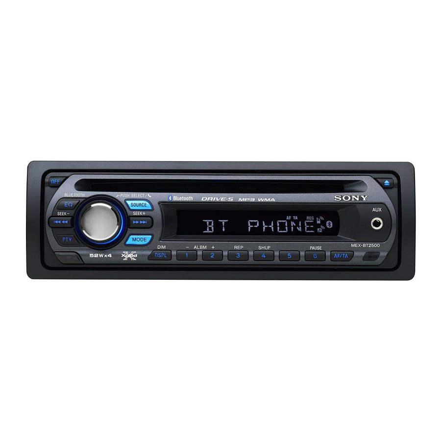
Seite 7: Location Of Controls And Basic Operations
MEX-BT2500 SECTION 2 This section is extracted from instruction manual. GENERAL (US and Canadian models) Location of controls and basic operations Main unit Card remote commander RM-X304 BLUETOOTH PUSH SELECT / SOURCE MODE SOURCE SEEK SEEK MODE ALBM SHUF PAUSE... - Seite 8 MEX-BT2500 (AEP and UK models) Location of controls and basic operations Main unit Card remote commander RM-X304 BLUETOOTH PUSH SELECT / SOURCE MODE SOURCE SEEK SEEK MODE ALBM SHUF PAUSE DSPL AF/ TA – DSPL SCRL MEX-BT2500 qg qh –...
- Seite 9 MEX-BT2500 (E model) Location of controls and basic operations Main unit Card remote commander RM-X304 BLUETOOTH PUSH SELECT / SOURCE MODE SOURCE SEEK SEEK MODE ALBM SHUF PAUSE DSPL SCRL – DSPL SCRL MEX-BT2500 qa qs qh qj – RESET L MODE button w;...
-
Seite 10: Connection Diagram
MEX-BT2500 (US and Canadian models) Cautions Connection diagram Equipment used in illustrations (not supplied) Appareils utilisés dans les illustrations (non fourni) To a metal surface of the car Equipo utilizado en las ilustraciones (no suministrado) Be sure to install this unit in the dashboard of the car First connect the black ground (earth) lead, then connect the as the rear side of the unit becomes hot during use. - Seite 11 -3). Mounting the unit in a Japanese TOYOTA NISSAN You may not be able to install this unit in some makes of Japanese cars. In such a case, consult your Sony dealer. max. size max. size 8 mm 8 mm...
- Seite 12 MEX-BT2500 (AEP and UK models) • When your car has built-in FM/MW/LW antenna (aerial) in the • Verbinden Sie das Stromversorgungskabel mit dem Cautions rear/side glass, connect the power antenna (aerial) control Equipment used in illustrations (not supplied) Gerät und den Lautsprechern, bevor Sie es mit dem lead (blue) or the accessory power supply lead (red) to the In Abbildungen dargestellte Geräte (nicht mitgeliefert)
- Seite 13 MEX-BT2500 Orient the release key correctly. Richten Sie den Löseschlüssel korrekt aus. Face the hook inwards. Orientez correctement la clé de déblocage. Der Haken muss nach innen Orientare la chiavetta di rilascio nel modo weisen. corretto. Tournez le crochet vers Plaats de ontgrendelingssleutel op de juiste l’intérieur.
- Seite 14 MEX-BT2500 Precautions -B Anbringen -B Bevestigen Regolazione dell’angolo di montaggio Setzen Sie Teil der Frontplatte wie in der Abbildung Breng deel van het voorpaneel aan op deel Regolare l’angolo di montaggio in modo che sia inferiore • Choose the installation location carefully so that the dargestellt an Teil des Geräts an und drücken Sie die...
- Seite 15 MEX-BT2500 (E model) Cautions Connection diagram Equipment used in illustrations (not supplied) Equipo utilizado en las ilustraciones (no suministrado) To a metal surface of the car Be sure to install this unit in the dashboard of the car First connect the black ground (earth) lead, then connect the as the rear side of the unit becomes hot during use.
-
Seite 16: Mounting Example
Piezas existentes suministradas con su automóvil Piezas existentes suministradas con su automóvil You may not be able to install this unit in some makes of Japanese cars. In such a case, consult your Sony dealer. Note To prevent malfunction, install only with the supplied screws... -
Seite 17: Disassembly
MEX-BT2500 SECTION 3 DISASSEMBLY • This set can be disassembled in the order shown below. 3-1. DISASSEMBLY FLOW FRONT PANEL SECTION Note: Illustration of disassembly is omitted. 3-2. COVER (Page 17) 3-3. CD MECHANISM DECK BLOCK (MG-101TA-188//Q) (Page 18) 3-4. ANTENNA BOARD 3-6. -
Seite 18: Cd Mechanism Deck Block (Mg-101Ta-188//Q)
MEX-BT2500 3-3. CD MECHANISM DECK BLOCK (MG-101TA-188//Q) 5 CD mechanism deck block (MG-101TA-188//Q) 3 two screws (PTT2.6 × 4) 2 connector (CN2) 4 bracket (CD) 1 screw (PTT2.6 × 6) 1 screw 1 two screws (PTT2.6 × 6) (PTT2.6 × 6) 3-4. -
Seite 19: Main Board
MEX-BT2500 3-5. MAIN BOARD 3 screw (PTT2.6 × 8) 2 ground sheet (TU) 4 three ground point screws (PTT2.6 × 6) 3 screw (PTT2.6 × 8) 5 MAIN board 1 Remove the solder. chassis block 3-6. SERVO BOARD 2 toothed lock screw (M1.7 ×... -
Seite 20: Chassis (T) Sub Assy
MEX-BT2500 3-7. CHASSIS (T) SUB ASSY 4 Remove the chassis (T) sub assy in the direction of arrow. 2 two precision screws (P1.7 × 2.2) 1 two precision screws (P1.7 × 2.2) 6 chassis (T) sub assy 5 Remove the three solders. -
Seite 21: Chassis (Op) Assy
MEX-BT2500 3-9. CHASSIS (OP) ASSY 6 chassis (OP) assy 1 tension spring (KF) 7 two coil springs (damper) (silver) 8 coil spring (damper) (green) 4 Slide the slider (R) in the direction of arrow A . 3 Slide the lever (D) in the direction of arrow B . -
Seite 22: Sled Motor Assy
MEX-BT2500 3-11. SLED MOTOR ASSY 2 three serration screws (M2 × 3) 3 sled motor assy 1 spring turn table spring stand Note: Never remove these parts since they were adjusted. chassis (OP) sub assy (bottom view) stand Note: Place the stand with care not to touch the turn table. -
Seite 23: Optical Pick-Up Section
MEX-BT2500 3-12. OPTICAL PICK-UP SECTION 2 optical pick-up section Note: Be careful not to touch the lens and hologram terminal when removing the optical pick-up section. 3-13. OP SERVICE ASSY (DAX-25A) 1 pan tapping screw (M1.4 × 2.5) 2 leaf spring (sub guide) -
Seite 24: Test Mode
MEX-BT2500 SECTION 4 TEST MODE Description of the Diagnostics function: 4. Contents of each display mode 4-1. Reset count display mode 1. Setting the Diag display mode With the power off, press the [4] t [5] t [4] ([4] button needs to be pressed for two seconds) button of set sequentially, and enter the diag function mode. - Seite 25 MEX-BT2500 4-5. CD error information display mode 4-6. OFFSET/FAILURE error display mode 4-5-1. Error description 0 6 1 X X X X X 0 5 1 Operating hours Error information Error description Error description Indication Description (in hexadecimal (0: OFFSET, 1: FAILURE)
- Seite 26 MEX-BT2500 MEMO...
-
Seite 27: Diagrams
MEX-BT2500 SECTION 5 DIAGRAMS • Note for Printed Wiring Boards and Schematic Diagrams • Circuit Boards Location Note on Printed Wiring Board: Note on Schematic Diagram: SERVO board • X : parts extracted from the component side. • All capacitors are in µF unless otherwise noted. (p: pF) SENSOR board •... -
Seite 28: Printed Wiring Boards - Main Section
MEX-BT2500 • See page 27 for Circuit Boards Location. • See page 27 for Semiconductor Location. 5-1. PRINTED WIRING BOARDS – MAIN Section – : Uses unleaded solder. F301 MAIN BOARD (CHASSIS) (AEP, UK) JC31 C431 C432 RL+ RL– GRN/BLK... -
Seite 29: Schematic Diagram - Main Section (1/3)
MEX-BT2500 • See page 34 for IC Block Diagrams. 5-2. SCHEMATIC DIAGRAM – MAIN Section (1/3) – (US,CND,E) (1/3) FRONT LCH+ FRONT LCH- REAR LCH+ C318 L301 2.2µH REAR LCH- R301 REAR RCH+ REAR RCH- BEEP FRONT RCH+ R302 C319 FRONT RCH- 0.22... -
Seite 30: Schematic Diagram - Main Section (2/3)
MEX-BT2500 • See page 34 for Waveforms. • See page 36 for IC Pin Function Description. 5-3. SCHEMATIC DIAGRAM – MAIN Section (2/3) – (2/3) UNISI Z-MUTE +3.3V DGND SYSRST (Page 29) CDON (US,CND,E) CDMON R547 BUSON 100k SGND R548 +8.3V... -
Seite 31: Schematic Diagram - Main Section (3/3)
MEX-BT2500 • See page 34 for IC Block Diagrams. 5-4. SCHEMATIC DIAGRAM – MAIN Section (3/3) – (3/3) Q410,420,430,40 C432 C431 MUTING Q430 R431 C430 RT1N140C (ANTENNA IN) R432 (AEP,UK) TUX-032//Q(US,CND,AEP,UK) Q440 RT1N140C TUX-032//Q2(E) R442 (TUNER UNIT) C441 R441 RT1N441C-TP-1... -
Seite 32: Printed Wiring Board - Key Board
MEX-BT2500 • See page 27 for Circuit Boards Location. 5-5. PRINTED WIRING BOARD – KEY Board – : Uses unleaded solder. KEY BOARD (COMPONENT SIDE) LSW901 – 912 S901 – 904 LED943 LED941 – 945, LED941 LED951 – 953 LED941, S901 LED951 –... -
Seite 33: Schematic Diagram - Key Board
MEX-BT2500 • See page 34 for Waveforms. • See page 34 for IC Block Diagrams. 5-6. SCHEMATIC DIAGRAM – KEY Board – LSW912(2/2) LSW911(2/2) LED942 LED941 CL-197HB1E SCRL (US,CND,E) CL-197HB1E LED943 PAUSE DISC SLOT CL-197HB1E AF/TA (AEP,UK) R941 R942 ILLUMINATION... - Seite 34 MEX-BT2500 • Waveforms IC300 TDA8588BJ/N2/R1 – KEY Board – – MAIN Board – IC501 ul (XOUT) IC971 rf (OSC) OUT-FL- C BUS OUT-FL+ 2.6 Vp-p 1.1 Vp-p OUT-RL- 30.4 µ s 25.5 µ s PGND3 500 mV/DIV, 20 µ s/DIV 1 V/DIV, 10 µ...
- Seite 35 MEX-BT2500 IC401 BD3444FS-E2 VCC/2 FADER: C BUS FADER FADER FADER FADER LOGIC 0 – -62dB/1dB step BASS: TREBLE: • fc = 100Hz • fc = 10kHz BASS/TREBLE • GAIN = ±20dB/1dB step • GAIN = ±20dB/1dB step • Q = 1 •...
- Seite 36 MEX-BT2500 • IC Pin Function Description MAIN BOARD IC501 MB90F045PF-G-9044-SPE1 (SYSTEM CONTROLLER) Pin No. Pin Name Description AREASEL0 to 1 to 3 Model destination signal input terminal AREASEL2 B-OUT SEL Blackout setting terminal "H": blackout effective BEEP Beep sound drive signal output to the power amplifier...
- Seite 37 Reset signal output to the bluetooth section "L": reset BT_POWER_ Power on/off control signal output terminal for the bluetooth section CTRL BUSON SONY bus on/off control signal output terminal "L": bus on TESTIN Test mode setting terminal "H": test mode Telephone muting detection signal input terminal TELATT At input of "H", the audio signal is attenuated by 20 dB...
-
Seite 38: Exploded Views
MEX-BT2500 SECTION 6 EXPLODED VIEWS NOTE: • -XX and -X mean standardized parts, so they • Items marked “*” are not stocked since they The components identified by mark 0 or dotted line with mark 0 are critical for safety. -
Seite 39: Front Panel Section
A-1267-957-A PANEL COMPLETE ASSY, FRONT (E) X-2149-228-2 CASE ASSY (for FRONT PANEL) (AEP, UK, E) X-2103-266-3 BUTTON ASSY (S) (US, CND, E) 3-251-320-01 EMBLEM (NO. 2.5), SONY X-2149-102-3 BUTTON ASSY (S) (AEP, UK) 3-229-100-01 SHEET (SW), ADHESIVE X-2176-838-1 PANEL SUB ASSY, FRONT (AEP, UK) -
Seite 40: Cd Mechanism Deck Section-1 (Mg-101Ta-188//Q)
MEX-BT2500 6-3. CD MECHANISM DECK SECTION (MG-101TA-188//Q) not supplied not supplied not supplied not supplied not supplied not supplied not supplied not supplied not supplied not supplied not supplied not supplied Ref. No. Part No. Description Remark Ref. No. Part No. -
Seite 41: Electrical Parts List
MEX-BT2500 SECTION 7 ANTENNA ELECTRICAL PARTS LIST NOTE: • Due to standardization, replacements in the • RESISTORS The components identified by mark 0 or dotted line with mark 0 are critical for safety. parts list may be different from the parts All resistors are in ohms. - Seite 42 MEX-BT2500 MAIN Ref. No. Part No. Description Remark Ref. No. Part No. Description Remark LSW907 1-786-998-12 SWITCH, TACT (WITH LED) (ALBM +, 2) R982 1-216-811-11 METAL CHIP 1/10W LSW908 1-786-998-12 SWITCH, TACT (WITH LED) (REP, 3) LSW909 1-786-998-12 SWITCH, TACT (WITH LED) (SHUF, 4)
- Seite 43 MEX-BT2500 MAIN Ref. No. Part No. Description Remark Ref. No. Part No. Description Remark 1-162-917-11 CERAMIC CHIP 15PF (AEP, UK) C507 1-162-917-11 CERAMIC CHIP 15PF C508 1-162-917-11 CERAMIC CHIP 15PF 1-162-917-11 CERAMIC CHIP 15PF C509 1-164-227-11 CERAMIC CHIP 0.022uF (AEP, UK)
- Seite 44 MEX-BT2500 MAIN Ref. No. Part No. Description Remark Ref. No. Part No. Description Remark D493 6-500-335-01 DIODE MC2838-T112-1 JC56 1-216-864-11 SHORT CHIP D502 8-719-060-48 DIODE RB751V-40TE-17 JC80 1-216-864-11 SHORT CHIP D503 8-719-988-61 DIODE 1SS355TE-17 < COIL/RESISTOR > D580 8-719-422-76 DIODE MA8075-M...
- Seite 45 MEX-BT2500 MAIN Ref. No. Part No. Description Remark Ref. No. Part No. Description Remark 1-216-845-11 METAL CHIP 100K 1/10W R534 1-216-833-11 METAL CHIP 1/10W (AEP, UK) R536 1-216-833-11 METAL CHIP 1/10W R537 1-216-845-11 METAL CHIP 100K 1/10W 1-414-595-11 INDUCTOR, FERRITE BEAD (AEP, UK)
- Seite 46 MEX-BT2500 SENSOR SERVO MAIN Ref. No. Part No. Description Remark Ref. No. Part No. Description Remark MISCELLANEOUS R709 1-216-049-11 RES-CHIP 1/10W ************** R800 1-216-821-11 METAL CHIP 1/10W R801 1-216-821-11 METAL CHIP 1/10W 1-964-881-11 CABLE, COAXIAL (WITH U.F.L CONNECTOR) R810 1-216-817-11 METAL CHIP...
-
Seite 47: Parts For Installation And Connections
MEX-BT2500 Ref. No. Part No. Description Remark Ref. No. Part No. Description Remark PARTS FOR INSTALLATION AND CONNECTIONS ************************************** X-3382-647-1 FRAME ASSY, FITTING 3-246-471-01 KEY (FRAME) 2-686-803-01 COLLAR 1-776-527-31 CORD (WITH CONNECTOR) (ISO) (POWER) (AEP, UK) 1-833-655-11 CORD (WITH CONNECTOR) (POWER) -
Seite 48: Revision History
MEX-BT2500 REVISION HISTORY Clicking the version allows you to jump to the revised page. Also, clicking the version at the upper right on the revised page allows you to jump to the next revised page. Ver. Date Description of Revision...