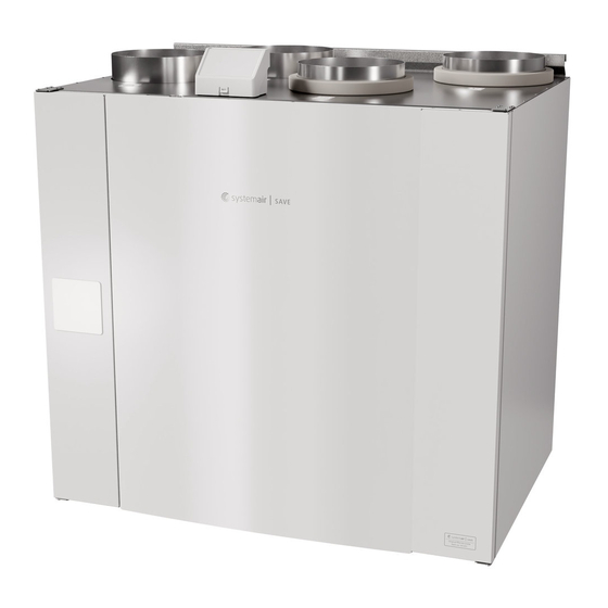
SystemAir SAVE VTC 500 Installationsanleitung
Elektrischer nacherhitzer
Vorschau ausblenden
Andere Handbücher für SAVE VTC 500:
- Bedienungsanleitung (66 Seiten) ,
- Installationsanleitung (66 Seiten)
Werbung
Verfügbare Sprachen
Verfügbare Sprachen
Quicklinks
These instructions cover installation process of the electrical reheater in SAVE VTC 500 right version unit.
Installation in left version unit is mirrored.
1. Remove the cover of reheater by loosening screws at the front (pos. 1).
2. Remove knobs (pos. 2) that will hold reheater in place. Insert electrical reheater (pos. 1) into dedicated
compartment, secure reheater with previously removed knobs (pos. 2).
3. Lead reheater control, TRIAC and overheat protection sensor wires through separate holes in the panel (pos.
3) to electrical connections compartment.
4.
• Connect reheater control wires to the terminal block marked as HEATER (pos. 4) on the main circuit
board. Connect blue wire to N socket, brown wire to L socket.
Systemair UAB Linų st. 101, LT–20174 Ukmergė, LITHUANIA
Phone: +370 340 60165 Fax: +370 340 60166
SAVE VTC 500 electrical reheater installation
• Connect TRIAC wires to the terminal block marked as TRIAC (pos. 5) on the main circuit board. Connect
black wire to G socket, brown wire to A1 socket, gray wire to A2 socket.
• Connect overheat protection sensor to any free analog input on the main circuit board (pos. 6). Connect
black wire to ground (GND), red fire to analog input.
5. Place back covers of reheater and the main circuit board and secure them with screws.
NOTE:
For more detailed information see a wiring diagram delivered with the unit.
Configuration
1. Go to Service menu
2. Enter password (default 1111)
3. Go to Components menu, select Heater menu and select type as Electrical. Do advanced settings if
necessary.
4. Configure overheat protection sensor. Go back to Input menu. Select ANALOG tab. Select the analog input
to which the overheat protection sensor is connected. Example if it is connected to AI4 on the main circuit
board, then select ANALOG INPUT 4 and select Overheat Temperature Sensor (OHT) from the input
type list.
5. Configure TRIAC. Go to Output menu. Select ANALOG tab then select TRIAC OUTPUT and set output type as
Y1 Heating.
1 (1)
212940-en_GB- vRev.01
Werbung

Inhaltszusammenfassung für SystemAir SAVE VTC 500
- Seite 1 SAVE VTC 500 electrical reheater installation 1 (1) These instructions cover installation process of the electrical reheater in SAVE VTC 500 right version unit. • Connect TRIAC wires to the terminal block marked as TRIAC (pos. 5) on the main circuit board. Connect Installation in left version unit is mirrored.
-
Seite 2: Konfiguration
SAVE VTC 500 elektrisk eftervärmare 1 (1) Dessa föreskrifter omfattar installationsprocessen av elektrisk eftervärmare i SAVE VTC 500 höger aggregat. • Anslut TRIAC ledningar till kopplingsplint TRIAC (pos. 5) på huvudkretskortet. Anslut den svarta ledningen Installation i vänsteraggregatet är spegelvänd. - Seite 3 Installation SAVE VTC 500 elektrischer Nacherhitzer 1 (1) Diese Anleitung behandelt den Installationsvorgang des elektrischen Nacherhitzers des SAVE VTC 500 in der • Schließen Sie die Kabel der Nacherhitzerregelung an den mit HEATER markierten Klemmenblock an (Pos. rechten Version. Der Einbau in der linken Version erfolgt spiegelbildlich.
- Seite 4 Installasjon av SAVE VTC 500 elektrisk ettervarmebatteri 1 (1) Denne instruksjonen dekker montering av elektrisk ettervarmebatteri i SAVE VTC 500 høyre versjon. • Koble TRIAC-ledninger til terminalblokken merket TRIAC (pos. 5) på hovedkortet. Koble svart ledning til G- Installasjon i venstre versjon gjøres på samme måte.
- Seite 5 Sähköisen jälkilämmittimen asentaminen SAVE VTC 500 -yksikköön 1 (1) Näissä ohjeissa on kuvattu sähköisen jälkilämmittimen asennus SAVE VTC 500 -yksikön oikeakätiseen malliin. • Kytke TRIAC-johtimet liittimille, jonka on merkitty TRIAC 5) pääpiirilevyllä Kytke musta johto - G liittimeen, Vasenkätinen malli on rakenteeltaan oikeakätisen mallin peilikuva.


