Herunterladen Inhalt Inhalt Diese Seite drucken
Inhaltsverzeichnis

Werbung

Verfügbare Sprachen
  • DE

Verfügbare Sprachen

  • DEUTSCH, seite 31
MOTOCOLTIVATORE
MOTOCULTEUR
EINACHSSCHLEPPER
MOTORCULTIVATOR
316
MOTOCULTORES
MOTOCULTIVADORES
MOTORPLOEG
USO E MANUTENZIONE
UTILISATION ET ENTRETIEN
BEDIENUNG UND WARTUNG
USE AND MAINTENANCE
USO Y MANTENIMIENTO
USO E MANUTENÇÃO
GEBRUIK EN ONDERHOUD
F 1364701A - Ott/2010

Werbung

Inhaltsverzeichnis
loading

Inhaltszusammenfassung für Bertolini 316

  • Seite 1 MOTOCOLTIVATORE MOTOCULTEUR EINACHSSCHLEPPER MOTORCULTIVATOR MOTOCULTORES MOTOCULTIVADORES MOTORPLOEG USO E MANUTENZIONE UTILISATION ET ENTRETIEN BEDIENUNG UND WARTUNG USE AND MAINTENANCE USO Y MANTENIMIENTO USO E MANUTENÇÃO GEBRUIK EN ONDERHOUD F 1364701A - Ott/2010...
  • Seite 3: Inhaltsverzeichnis

    INDICE DEL CONTENUTO PREMESSA - Informazioni e norme generali ....1 Prima dell’uso della mac china, - Spiegazione dei simboli ......1 leggete attentamente questo - Dati per l’identificazione ......2 manuale e conserva-telo per - Misure d’ingombro .........2 future consultazioni. - Velocità ...........2 La Ditta costruttrice si riserva il - Dati tecnici ..........2 diritto di effettuare modifiche,...
  • Seite 4: Marcatura Ed Identificazione

    MARCATURA ED IDENTIFICAZIONE Il numero di matricola della macchina è stampigliato sul lato destro della scatola cambio, sopra il coperchio (Fig. 1). Al ricevimento della macchina, controllare l’esistenza del marchio “CE” sul lato sinistro della scatola cambio. IMPORTANTE! Nelle eventuali richieste di assistenza tecnica o nelle ordinazioni di parti di ricambio, citate sempre il numero di (Fig.
  • Seite 5: Flangiatura Attrezzi

    FLANGIATURA ATTREZZI...
  • Seite 6: Comandi

    COMANDI (Fig. 2) 1) Leva arresto motore 2) Leva comando frizione 3) Leva bloccaggio differenziale 4) Leva freno sx. 5) Leva freno dx. 6) Leva bloccaggio verticale manubrio 7) Leva comando P. di P. 8) Leva comando marce 9) Comando acceleratore Fig.
  • Seite 7: Prese Di Potenza

    PRESE DI POTENZA (Fig. 5) Fig.5 (Dati riferiti a 3.600 g/min) Le macchine sono dotate di N° 2 P. di P. po- steriori, di cui una indipendente a 2 velocità, 585 e 900 g/1’, e l’altra sincronizzata con il cambio. La P.
  • Seite 8: Dispositivi Di Sicurezza

    supporto S spostando l’impugnatura verso dx Fig.8 4) Tirare la leva 10 ( Fig. 2 ) e ruotare il pian- tone in senso antiorario (sinistrorso), come indicato in Fig. 7/B. 5) Riportare la leva 10 in posizione originale bloccando in tal modo il piantone. 6) Inserire la stegola 7 nella sede di supporto N.B.
  • Seite 9: Avviamento Elettrico

    AVVIAMENTO ELETTRICO MOTORE Fig. 12 (Fig. 12) Per l’avviamento del motore occorre eseguire le seguenti operazioni: 1) Introdurre la chiave nell’interruttore di avviamento e ruotarla in posizione 1 (vedi schema). 2) Ruotare ulteriormente la chiave in po- sizione 2 e, appena il motore è avviato, abbandonarla.
  • Seite 10: Lubrificazione

    Fig.13 LUBRIFICAZIONE SOSTITUZIONE OLIO (Fig. 13) SCATOLA CAMBIO (Fig. 14) TIPO DI LUBRIFICANTE La sostituzione deve avvenire a olio caldo, Motore: Vedere libretto istruzione motore. svitando il tappo A e il tappo B completo di Motocoltivatore: Utilizzare solo olio ESSO asta livello olio.
  • Seite 11: Istruzioni Montaggio Freni

    ISTRUZIONI MONTAGGIO FRENO Fig. 15a (Fig. 15) 1) Appoggiare il motore su un supporto stabile. 2) Allentare le viti di fissaggio della ruota al semiasse (Fig. 15a ). 3) Sollevare il motocoltivatore dal lato presa di forza e togliere completamente le ruote. Fig.
  • Seite 12: Controlli E Regolazioni Motore

    CONTROLLI E REGOLAZIONI MOTORE Per effettuare i controlli del motore e dei suoi relativi organi consultate il libretto Uso e Manutenzione del motore allegato, rivol- gendoVi esclusivamente, per le regolazioni, alle Stazioni di Servizio Autorizzate dalla Ditta costruttrice il motore. FRIZIONE (Fig.
  • Seite 13: Applicazione Fresa

    APPLICAZIONE FRESA Caratteristiche tecniche Giri fresa: 1ª velocità 217 giri/min, 2ª velocità 333 giri/min con motore a 3.600 giri/min. Collegamento al MTC ( fig. 19) - Montare sull’albero fresa il giunto di col- legamento (1) e le 2 spine di centraggio (2) nei relativi fori.
  • Seite 14: Barra Falciante Frontale

    BARRA FALCIANTE FRONTALE (Fig.21) Collegamento al motocoltivatore Regolazione dell’altezza della barra fal- L’applicazione della barra al motocoltivatore ciante viene fatta utilizzando il relativo attacco rapido. Dovendo falciare su terreni accidentati, è necessario regolare l’altezza di taglio della Registrazione del gioco tra perno centrale barra falciante nel modo seguente: e pastiglie - Allentare il dado 1.
  • Seite 15: Aratri

    ARATRI Fig. 22 Gli aratri studiati per i motocoltivatori sono stati particolarmente messi a punto per ottenere dei buoni lavori di aratura senza af- faticare eccessivamente l’operatore. L’aratro voltaorecchio a 180° (Fig. 22) è particolar- mente indicato laddove si debbano eseguire lavorazioni nei due sensi come rincalzature o scalzature in filari di vigneti o frutteti.
  • Seite 16: Manutenzione

    MANUTENZIONE RUMORE AEREO Valore di pressione acustica rilevata a NORME GENERALI 1,6 m. dal suolo, al centro delle stegole, Una regolare manutenzione è estremamente con strumento (B&K 2230) rivolto verso importante per ottenere migliori prestazioni ed il motore. Massimo livello di pressione acustica un funzionamento sicuro nel tempo.
  • Seite 17: Informations Et Normes Générales

    TABLE DES MATIERES AVANT-PROPOS Av a n t d ' u t i l i s e r l a m o t o - - Informations et normes générales ..15 faucheuse, lisez attentive-ment - Explication des symboles ....15 ce manuel et gardez-le pour - Données pour l’identification ....16 d'autres consultations.
  • Seite 18: Marquage Et Identification

    MARQUAGE ET IDENTIFICATION Vérifiez à la réception de la machine si la plaque d'identification a été fixée et si elle porte la marque “CE". La plaque doit être positionnée sur la boîte à vitesse, à côté du numéro de série estampillé sur le carter. AT T E N T I O N ! - E n c a s d e b e s o i n d'assistance technique ou pour des commandes de pièces de rechange,...
  • Seite 19: Bridage Outils

    BRIDAGE OUTILS...
  • Seite 20: Commandes

    COMMANDES (Fig. 2) 1) Motorstop 2) Levier commande embrayage 3) Levier blocage différentiel 4) Levier frein gauche. 5) Levier frein droit. 6) Levier réglage guidon en hauteur 7) Levier prise de force 8) Tige commande vitesses 9) Levier accélérateur Fig. 2 10) Levier réglage guidon en horizontal AVEC DEMARRAGE ELECTRIQUE 12) Clé...
  • Seite 21: Prise De Force

    PRISE DE FORCE (Fig. 5) Fig.5 (Données se rapportent à 3.600 t/min) Les machines possèdent N° 2 prises de force postérieures, dont une indépendante à 2 vitesses, 585 et 900 V1', et l’autre synchronisée avec la boite à vitesse. La prise de force indépendante est actionnée par le levier 7 (Fig.2).
  • Seite 22: Dispositifs De Sécurité

    3) Retirer les mancherons 7 ( Fig. 2 ) des Fig.8 sièges de support S. 4) Tirer le levier 10 ( Fig. 2 ) et pivoter la co- lonne dans le sens contraire aux aiguilles d’une montre (de droite à gauche), comme indiqué sur la Fig.
  • Seite 23: Démarrage Électrique

    DEMARRAGE MOTEUR Fig. 12 (Fig. 12) Pour faire démarrer le moteur suivre les opérations suivantes: 1) Introduire la clé dans l’interrupteur et la mettre en position 1 (voir schéma). 2) Tourner ultérieurement la clé en position 2 et, I’abandonner dès que le moteur tourne. N.B.: Lorsque le moteur tourne laisser la clé...
  • Seite 24: Ravitaillement

    Fig.13 LUBRIFICATION (Fig. 13) Moteur: Voir livret des instructions pour le moteur. VIDANGE HUILE Motoculteur: Suivre les instructions indiquées BOITE A VITESSE (Fig. 14) dans le tableau- Utiliser exclusivement de l’huile ESSO UNIFARM 15-40 W et de la La vidange doit s’effectuer avec l’huile graisse ESSO MULTIPURPOSE.
  • Seite 25: Instruction Montage Frein

    INSTRUCTIONS Fig. 15a POUR LE MONTAGE DU FREIN (Fig. 15) 1) Poser le moteur sur un support stable. 2) Desserrer les vis de fixation de la roue au demi-essieu (Fig. 15a ). 3) Soulever le motoculteur du côté de la prise de force et enlever totalement les roues.
  • Seite 26: Moteur

    CONTROLES ET REGLAGES MOTEUR Pour effectuer les contrôles du moteur et de ses pièces consulter le livre Utilisation et Entretien du moteur, adressez-vous exclusivement, pour les réglages, aux Stations Service Autorisées par le Fabricant du moteur. EMBRAYAGE (Fig. 16) Fig.16 Le levier de commande embrayage (2) doit avoir une course d’environ 5 mm, avant l’embrayage commence à...
  • Seite 27: Application Fraise

    APPLICATION FRAISE Caractéristiques techniques Tours fraise : 1ère vitesse 217 tours/min, 2ème vitesse 333 tours/min avec moteur à 3600 tours/min. Accrochage au MTC ( fig. 19) - Monter sur l’arbre de la fraise le joint de liaison (1) et les prises de centrage (2) dans les trous respectifs.
  • Seite 28: Application Barre Faucheuse

    BARRE FAUCHEUSE FRONTALE (Fig.21) A t t e l a g e m o t o c u l t e u r Réglage de la hauteur de la barre faucheuse L’application de la barre au motoculteur s’ef- fectue en utilisant l’attelage rapide. Pour faucher sur des terrains accidentés, il est nécessaire de régler la hauteur de coupe Réglage du jeu entre le pivot central et...
  • Seite 29: Charrues

    CHARRUES Fig. 22 Les charrues étudiées pour les motocul- teurs ont été mises au point pour obtenir un bon travail de labourage sans fatiguer l’opérateur. La charrue basculante de180° (Fig. 22) est particulièrement indiquée pour les endroits où l’on doit exécuter des travaux dans les deux sens comme par exemple le rechaussement ou le déchaus- sement des vignes ou des vergers.
  • Seite 30: Entretien

    ENTRETIEN BRUIT AERIEN NORMES GENERALES Valeur de la pression acoustique relevée Un entretien régulier est extrêmement important à 1,6 m. du sol, mesurée au centre du pour obtenir les meilleures prestations possibles guidon, le phonomètre (B&K 2230) tourné et un fonctionnement sûr au cours des vers le moteur.
  • Seite 31: Allgemeine Hinweise Und Vorschriften . 29 - Zeichenerklarung

    INHALTSVERZEICHNIS VORBEMERKUNG - Allgemeine Hinweise und Vorschriften . 29 Lesen Sie dieses Handbuch - Zeichenerklarung ......... 29 vor der Inbetriebnahme der - Identifizierungsdaten ......30 Maschine sorgfältig durch und - Abmessungen ........30 bewahren Sie es für zukünftige - Fahrgeschwindigkeiten ......30 Konsultationen auf.
  • Seite 32: Identifizierungs Kennzeichnung

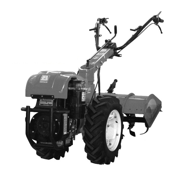
    IDENTIFIZIERUNGS KENNZEICHNUNG Die Maschinennummer ist auf der rechten Seite des Getriebegehäuses über der Schutzverkleidung eingestanzt (Abb.1); die “CE"-Kennzeichnung befindet sich auf der linken Seite des Getriebegehäuses. Kontrollieren Sie bei Erhalt der Maschine, ob das Identifkierungsschild mit der “CE"-Marke vorhanden ist. W I C H T I G ! - G e b e n S i e b e i e v t l .
  • Seite 33: Anschlußflansch

    ANSCHLUßFLANSCH...
  • Seite 34: Bedienungselemente

    BEDIENUNGSELEMENTE (Abb. 2) 1) Motorstop 2) Kupplungshebel 3) Differentialsperrhebel 4) Linker Bremshebel. 5) Rechter Bremshebel. 6) Lenkholmhöhenverstellungshebel 7) Zapfwellenhebel 8) Gangschaltungsgestänge 9) Gashebel 10) Lenkholmseitenverstellungshebel Abb. 2 MIT ELEKTROANLASSER 12) Zündschlüssel P = Parkleuchten 0 = Stromkreisläufe nicht aktiviert Abb. 3 1 = Stromkreisläufe aktiviert 2 = Anlassen 13) Maschinentypen mit Dieselmotor...
  • Seite 35: Zapfwellen

    ZAPFWELLEN (Abb. 5) (Werte auf 3600 U/min bezogen) Abb.5 Die Maschine ist mit zwei Heckzapfwel- len ausgerüstet, von denen eine mit zwei Geschwindigkeiten (585 und 900 U/min) unabhängig steuerbar ist und die andere mit dem Getriebe gleichgeschaltet ist. Die unabhängige Zapfwelle wird über den Hebel 7 (Abb.
  • Seite 36: Sicherheitsvorrichtungen

    4) Hebel 10 ziehen und Lenkholm gegen den Abb.8 Uhrzeigersinn (linksdrehend) schwenken, wie es auf derAbb. 91B dargestellt ist. 5) Hebel 10 wieder in die Originalstellung zurückbringen und den Lenkholm so blockieren. 6) Die Hebel 7 wieder in ihren Lagersitzen S befestigen.
  • Seite 37: Elektroanlasser

    ANLASSEN DES MOTORS (Abb. 12) Abb. 12 Gehen Sie zum Anlassen des Motors wie folgt vor: 1) Zündschlüssel in das Zündschloß stecken und in Stellung 1 drehen (siehe Skizze). 2) Den Zündschlüssel bis in die Stellung 2 weiterdrehen und ihn loslassen, sobald der Motor läuft.
  • Seite 38: Treibstoff

    Abb.13 SCHMIERUNG (Abb. 13) ÖLWECHSEL IM GETRIEBEGEHÄUSE (Abb. 14) SCHMIERMITTELTYP Der Ölwechsel muß bei warmem Öl erfolgen. Motor: Motoren-Betriebsanleitung bea- Ablaßpfropfen A und Einfüllpfropfen mit Meß- chten. stab B abschrauben und Öl ablaufen lassen. Einachsschlepper: Nur Öltyp ESSO UNI- Nach vollständigem Ölablauf Ablaßpfropfen A FARM 15 - 40 W und Fettmarke ESSO wieder anschrauben und durch das Einfülloch MULTIPURPOSE verwenden.
  • Seite 39: Montage Anleitungen Fur Die Bremse

    MONTAGEANLEITUNGEN Abb. 15a FÜR DIE BREMSE (Abb. 15) 1) Den Motor auf einem stabilen Gestell ablegen. 2) Die Befestigungsschrauben des Rades an der Achswelle lockern (Abb. 15a ). 3) Den Motorkultivator auf der Seite der Zapfwelle anheben und die Räder vollständig entfernen.
  • Seite 40: Motors

    KONTROLLEN UND EINSTELLUNGEN MOTOR Zur Ausführung der Kontrollen des Motors und seiner Einzelteile beachten Sie bitte das Motoren-Bedienungs- und Wartun- gs-handbuch. Zur Einstellung des Motors richten Sie sich ausschließlich an die von der Herstellerfirma des Motors autorisierten Werkstätten. KUPPLUNG Abb.16 (Abb.
  • Seite 41: Einbau Der Frase

    EINBAU DER FRÄSE Technische Daten Drehzahlen der Fräse : 1. Geschwindigkei- tsstufe 217 U/min, 2. Geschwindigkeitsstufe 333 U/min mit dem Motor bei 3600 U/min. Einbau am Einachsschlepper (Abb.19) - Montieren Sie auf der Antriebswelle der Frä- se das Verbindungsstück (1) und die beiden Zentrierungsstifte (2) in den entsprechenden Löchern.
  • Seite 42: Anbau Des Frontmähbalken

    ANBAU DES FRONTMÄHBALKENS (Abb.21) Anbau am Einachsschlepper Zum Anbau des Frontmähbalkens am Eina- Hauptbolzen nie völlig mit den Metall- chser ist das entsprechende Verbindungs-teil zwischenscheiben; lassen Sie stets ein (Quickfit) zu verwenden. Spiel von mindestens 0,1 mm. Einstellung des Spiels zwischen dem Einstellung der Schnitthöhe Hauptbolzen und den Metallzwischen- Falls Sie unebenes Gelände bearbeiten...
  • Seite 43: Pfluge

    PFLÜGE Abb. 22 Die Pflüge, die für die Einachsschlepper entwickelt worden sind, sind speziell so kon- struiert worden, daß gute Pflugergebnisse erreicht werden können, ohne den Benutzer der Maschine übemmäßig zu belasten. Der 180°-Wendepflug (Abb. 22) ist besonders für Arbeiten geeignet, bei denen in zwei Richtun- gen gepflügt werden muß, wie beispielsweise zum Häufeln oder Freilegen in Reihen von Weinbergen oder Obstgärten.
  • Seite 44: Kontrolle Und Schmierung

    WARTUNG GERÄUSCHPEGEL ALLGEMEINE VORSCHRIFTEN Gemessener akustischer Schalldruck in einer Eine regelmäßige Wartung ist extrem wichtig, Höhe von 1,60 m vom Boden, in der Mitte um die besten Leistungen und einen dauerhaft zwischen den Lenkholmen, mit auf den Motor sicheren Betrieb zu gewährleisten. gerichtetem Meßgerät (B&K 2230).
  • Seite 45: Information And General Rules

    INDEX PREFACE - Information and General Rules ....43 Before using the machine, read - Explanation of symbols .......43 this manual carefully and keep - Identification data ........44 it at reach for future reference. - Overall dimensions .......44 The Manufacturer reserves the - Speed ...........44 right to make modifications, - Technical data ........44...
  • Seite 46: Identification Data

    IDENTIFICATION DATA On receiving the machine check for the “CE” label on the right hand side of the Gearbox (clutch side) near the serial number printed on the sump (see Fig. 1). IMPORTANT! Whenever requesting technical service or ordering spare parts, always give the serial number of the machine in question (Fig.
  • Seite 47 FLANGING IMPLEMENTS...
  • Seite 48 CONTROLS (Fig. 2) 1) Motorstop 2) Clutch control lever 3) Differential lock lever 4) Left brake lever. 5) Right brake lever. 6) Handlebar height adjustment lever 7) Power Take-off lever 8) Gear control rod 9) Throttle lever Fig. 2 10) Handlebar horizontal adjustment lever WITH ELECTRIC START 12) Start key Fig.
  • Seite 49: Power Take-Off

    POWER TAKE-OFF (Fig. 5) Fig.5 (data refers to 3,600 rpm) The machines are equipped with n° 2 rear P T.O. - 1 independent at 2 speeds 585 and 900 rpm and the other synchronized with the gearbox. The independent P.T.O. is activated by means of lever 7 (Fig.
  • Seite 50: Safety Devices

    4) Pull lever 10 ( Fig. 2 ) and rota- Fig.8 te the column in anti-clockwise direc- tion (leftwards), as shown in Fig. 7/B. 5) Bring lever 10 back to its original position to thus lock the column. 6) Put handles back on support S. N.B.
  • Seite 51: Engine Start

    ENGINE START Fig. 12 (Fig.12) In order to start the engine, proceed as follows: 1 ) Insert the ignition key in the start switch and turn into position 1 (see diagram). 2) Turn the key further into position 2, and when engine has started, release.
  • Seite 52: Tyre Pressure

    Fig.13 LUBRICATION (Fig. 13) GEAR BOX OIL REPLACEMENT (Fig. 14) TYPE OF LUBRICANT Engine: see engine manual. Oil must be replaced when hot, by unscrewing Motorcultivator: use only ESSO UNIFARM fill cap A and fill cap B equipped with an oil 15-40 W oil and ESSO MULTIPURPOSE dipstick.
  • Seite 53 BRAKE ASSEMBLY INSTRUCTIONS Fig. 15a (Fig. 15) 1) Place the engine on a stable support. 2) Unscrew the wheel fixing screws (Fig. 15a ). 3) Lift the engine driven cultivator from the power take-off side and completely remove the wheels. Fig.
  • Seite 54 CONTROLS AND ADJUSTMENT ENGINE For checking the engine and its related parts, consult the Use and Maintenance Manual enclosed. Have adjustments made only at service centres authorised by the engine manufacturer. CLUTCH Fig.16 (Fig. 16) The clutch lever (2) must have a stroke of ap- proximately 5 mm.
  • Seite 55 FITTING THE ROTARY HOE Technical characteristics: Rotary Hoe speed : 1 speed: 217 rpm speed 333 rpm., with engine at 3600 rev/min. Connection to motorcultivator (Fig. 19) - Fit the connection joint (1) to the rotary hoe shaft and fit the two centering pins (2) into the corresponding holes.
  • Seite 56 FRONTAL CUTTER BAR APPLICATION (Fig.21) Connection to motor cultivator Cutter bar height adjustment Couple the cutter bar by using the Quickfit. When working on bad terrain, it is neces- sary to adjust the mower’s cut height in the Clearance adjustment between the cen- following way: tral pin and pads - Loosen nut 1.
  • Seite 57 PLOUGHS Fig. 22 The ploughs that have been designed for use with cultivators have been specially engineered to ensure that a high standard of ploughing is achieved without overtiring the operator. The 180° Scandinavian plough (Fig. 22), is ideal for ploughing in two directions, e.g. for ridging or hoeing between rows of vines or fruit trees.
  • Seite 58: Airborne Noise

    MAINTENANCE AIRBORNE NOISE Acoustic pressure recorded at 1,6 m off the GENERAL RULES ground in the centre of the handlebars by a B Regular maintenance is extremely important & K 2230 instrument facing the engine. for ensuring the best performance and long- Maximum level of acoustic pressure sta- life of the motorcultivator.
  • Seite 59: Informacionesy Normas Generales

    INDICE DEL CONTENIDO PREMISA - Informaciones y normas generales ..57 Antes de utilizar la máquina, - Explicación de los símbolos ....57 leer atentamente el presente - Datos para la identificación ....58 manual conservándolo para - Dimensiones ........58 eventuales futuras consultas. - Velocidad ..........
  • Seite 60: Datos Para La Identificación

    MARCADO E IDENTIFICACION El número de matrícula de la máquina está aplicado sobre el lado derecho de la caja de cambios, sobre la tapa (Fig. 1); la marca “CE” colocada sobre el lado izquierdo de la caja de cambios. Al recibir la máquina controlar la existencia de la etiqueta “CE”.
  • Seite 61: Bridos Aperos

    BRIDA APEROS...
  • Seite 62: Mandos

    MANDOS (Fig. 2) 1) Motorstop 2) Palanca mando embrague 3) Palanca bloqueo diferencial 4) Palanca freno izquierdo. 5) Palanca freno derecho 6) Palanca regulación manillar en altura 7) Palanca Toma de Fuerza 8) Varilla mando marchas 9) Palanca acelerador 10) Palanca regulación manillar en horizontal Fig.
  • Seite 63: Toma De Fuerza

    TOMA DE FUERZA (Fig. 5) Fig.5 (Datos referidos a 3.600 rev/min.) Las máquinas están provistas de N° 2 T. de F. posteriores, de las cuales una independiente de 2 velocidades, 585 y 900 rev./min., y la otra sincronizada con el cambio. La T.
  • Seite 64: Dispositivos De Seguridad

    3) Quitar las manceras 7 (Fig. 2) de las sedes Fig.8 de soporte S. 4) Jalar la palanca 10 (Fig. 2) y hacer girar el soporte en sentido contrario (hacia la izquier- da), como se indica en la Fig. 7/B. 5) Volver a poner la palanca 10 en la posi- ción original, bloqueando de esta manera el soporte.
  • Seite 65: Encendido Motor

    ENCENDIDO MOTOR Fig. 12 (Fig. 12) Para el encendido del motor es necesario seguir las siguientes operaciones: 1) Introducir la llave en el interruptor de arranque y hacerla girar hacia la posición 1 (ver esquema). 2) Hacer girar la llave ulteriormente a la posición 2 y, apenas el motor ha arrancado, soltarla.
  • Seite 66: Lubricacion

    Fig.13 SUSTITUCION LUBRICACION ACEITE CAJA DE CAMBIOS (Fig. 13) (Fig. 14) TIPOS DE LUBRICANTE La sustitución debe efectuarse con el aceite Motor: Ver el manual de instrucciones del caliente, desenroscando el tapón A y el tapón motor. B completo con varilla nivel de aceite. Una Motocultor: Utilizar solamente aceite ESSO vez terminada la salida del aceite, colocar UNIFARM 15-40 W y grasa ESSO MULTI-...
  • Seite 67: Instrucciones Montaje Freno

    INSTRUCCIONES MONTAJE FRENO Fig. 15a (Fig. 15) 1) Apoyar el motor sobre un soporte estable. 2) Aflojar los tornillos de fijación de la rueda al semieje (Fig. 15a ). 3) Elevar la motocultivadora del lado toma de fuerza y retirar completamente las ruedas. Fig.
  • Seite 68: Controles Y Regulaciones Motor

    CONTROLES Y REGULACIONES MOTOR Para efectuar los controles del motor y de sus respectivos elementos consultar el Manual de Uso y Mantenimiento del motor anexo. Para las regulaciones dirigirse exclu- sivamente a las Estaciones de Servicio Autorizadas por el Fabricante del motor. EMBRAGUE (Fig.
  • Seite 69: Aplicación Fresa

    APLICACION FRESAS Características técnicas Revoluciones fresa (MTC MK 6): 1° velocidad 217 rev./min., 2° velocidad 333 rev./min. con motor a 3.600 rev./min. Conexión al Motocultor ( fig. 19) - Montar en el eje fresa la junta de conexión (1) y las 2 clavijas de centrado (2) en los respectivos agujeros.
  • Seite 70: Aplicación Barra Segadora Frontale

    BARRA SEGADORA FRONTALE (Fig.21) Regulación de la altura de la barra de la Conexión al motocultivador segadora La aplicación de la barra al motocultor es Debiendo segar sobre terrenos accidentados, realizada utilizando el correspondiente en- es necesario regular la altura de corte de la ganche rápido.
  • Seite 71: Arados

    ARADOS Fig. 22 Los arados para el motocultor han sido estudiados para obtener buenos trabajos de arado sin fatigar excesivamente al ope- rador. El arado “gira oreja” a 180° (Fig. 22) es particularmente indicado en los lugares en donde deban realizarse trabajos en dos sentidos como recalzado y excavado en hileras de viñas o plantaciones de fruta.
  • Seite 72: Ruido Aéreo

    MANTENIMIENTO RUIDO AEREO NORMAS GENERALES Valor de presión acústica tomada a 1,6 m Es muy importante llevar a cabo un regular del suelo, en el centro de las manceras, mantenimiento para obtener las mejores pre- con instrumento (B&K 2230) dirigido hacia staciones y un funcionamiento seguro en el el motor.
  • Seite 73: Informação E Normas Gerais

    INDICE DO CONTEUDO INTRODUÇÃO - Informação e normas gerais ....71 Antes do uso da máquina, - Explicação dos símbolos ..... 71 leia este manual com atenção - Indentificação ........72 e guarde-o para consultas - Dimensões .......... 72 futuras. A Empresa constru- - Velocidade ..........
  • Seite 74: Marcas E Identificação

    MARCAS E IDENTIFICAÇÃO O número de matrícula da máquina está impressa no lado direito da caixa de velocidades, em cima da tampa (Fig. 1); a marca CE está no lado esquerdo da caixa de velocidades. Ao recebimento da máquina controle a esistência da etiqueta “CE”. IMPORTANTE Nos eventuais pedidos de assistência técnica ou nas encomendas de peças,...
  • Seite 75: Flange Equipos

    FLANGE EQUIPOS...
  • Seite 76: Comandos

    COMANDOS (Fig. 2) 1) Motorstop 2) Manete de comando da embraiagem 3) Manete bloqueio diferencial 4) Manete do travão esquerdo 5) Manete do travão direito. 6) Manete regulação em altura do guiador 7) Manete da Tomada de Força 8) Haste de comando das marchas 9) Manete do acelerador Fig.
  • Seite 77: Tomada De Força

    TOMADA DE FORÇA (Fig. 5) Fig.5 (Os dados referem-se a 3.600 r.p.m.) Os motocultivadores estão equipados com n° 2 tomadas de força posteriores, cuja uma indipendente a 2 velocidades, 585 e 900 rpm, e outra sincronizada com a caixa. A T.D.F. indipendente é acionada atravéz a manete 7 (Fig.
  • Seite 78: Dispositivos De Segurança

    4) Tirar a manete 10 e rodar a coluna em Fig.8 sentido contrário (para a esquerda), como indicado na Fig. 7/B. 5) Pôr novamente a manete 10 na sua posição original para assim bloqueiar a coluna. 6) Inserir os braços 7 no suporte S. N.B.
  • Seite 79: Arranque Do Motor

    ARRANQUE DO MOTOR Fig. 12 (Fig. 12) Para o arranque do motor é preciso executar as seguintes operações: 1) Introduzir a chave no interuptor e virá-la na posição 1 (vêr esquema). 2) Virar a chave ulteriormente até á posição 2, de modo que o motor arrancar, deixando ficar a chave.
  • Seite 80: Reabastecimento

    Fig.13 SUBSTITUIÇÃO OLEO CAIXA REABASTECIMENTOS (FIG. 14) (Fig.13) A substituição tem que ser feita com o óleo quente, desapertando a tampa A e a tampa B TIPO DE LUBRIFICANTE equipada com a vareta nível óleo. Terminada Motor: Vêr manual de instruções do motor. a saída de óleo, colocar a tampa A e introdu- Motocultivador: Usar sómente óleo ESO zir o óleo novo no buraco B (2,5 Kg.).
  • Seite 81: Instruções De Montagem Do Travão

    INSTRUÇÕES DE MONTAGEM Fig. 15a DO TRAVÃO (Fig. 15) 1) Apoiar o motor sobre um suporte estável. 2) Afrouxar os parafusos de fixação da roda ao semieixo (Fig. 15a). 3) Erguer o moto-cultivador pelo lado da tomada de força e tirar completamente as rodas.
  • Seite 82: Contrôles E Regulações Motor

    CONTRôLES E REGULAÇõES MOTOR Para efectuar os controles do motor e dos seus componentes, consultar o manual de Uso e Manutenção do motor em anexo. Para as regulações, dirigir-se exclusiva-mente aos Centros de Servício autorizados pelo fabricante do motor. EMBRAIAGEM (Fig.
  • Seite 83: Aplicação Da Fresa

    APLICAÇÃO DA FRESA Características técnicas Rotações fresa : 1 velocidade - 217 rpm, 2 velocidade - 333 rpm com motore a 3.600 rpm Coligamento ao motocultivador (Fig. 19) - Montar a juntura de coligamento (1) e as 2 tomadas de centragem (2) nos relativos buracos do eixo da fresa.
  • Seite 84: Barra De Corte Frontal

    BARRA DE CORTE FRONTAL (Fig.21) Aplicação ao motocultivador Regulação da altura da barra de corte A aplicação da barra ao motocultivador é feita Quando se ceifar em terrenos acidentados, é usando o relativo engate rápido. necessário regular a altura de corte da barra de corte na seguinte maneira: Registracção do jogo entre perne central - Aliviar o dado 1.
  • Seite 85: Arados

    ARADOS Fig. 22 Os arados dos motocultivadores foram projectados para obter um bom trabalho de aradura sem cansar demasiadamente o operador. O arado reversível a 180° (Fig. 22) é particularmente indicado para executar tra- balhos nos dois sentidos, como abacelar ou cavar nas fileiras dos vinhedos e pomares.
  • Seite 86: Manutenção

    MANUTENÇÃO RUÍDO AÉREO Valor de pressão acústica relevada a 1,6 Normas gerais m do chão, ao centro dos braços, com Uma manutenção periódica é muito impor- instrumento (B&K 2230) em direção do tante para obter uma melhor prestação e motor. seguro funcionamento da máquina.
  • Seite 87: Ter Informatie En Algemene Richtlijnen

    INHOUDSOPGAVE TER INLEIDING - Ter informatie en algemene richtlijnen . 85 Lees vóór de ingebruikname - Verklaring van de symbolen ....85 van de machine aandachtig - Identificatiegegevens ......86 deze handleiding en hou deze - Afmetingen ........... 86 bij de hand voor toekomstige raadpleging.
  • Seite 88: Identificatiegegevens

    IDENTIFICATIEGEGEVENS Kijk bij de levering van de machine na of het identificatieplaatje zich bevindt op de versnellingsbak, in de nabijheid van het gegraveerde serienummer, en verifiëer of dit het "CE" merkteken draagt (fig. 1). BELANGRIJK! Vermeld steeds het serienummer van de minimaaier in kwestie wanneer U technische bijstand verlangt of (Fig.
  • Seite 89: Flens Werktuigen

    FLENS WERKTUIGEN...
  • Seite 90: Bedieningshendels

    BEDIENINGSHENDELS(Fig. 2) 1) Motorstop 2) Koppelingshendel 3) Hendel differentieelblokkering 4) Linkerremhendel 5) Rechterremhendel 6) Bedieningshendel instellen stuurhoogte 7) Aftakashendel 8) Versnellingspook 9) Gashendel Fig. 2 10) Bedieningshendel horizontale instellingstuur MET ELECTRISCHE STARTER 12) Contactsleutel P = parkeerlichten Fig. 3 0 = geen spanning op electrisch circuit 1 = spanning op electrisch circuit 2 = starten 13) Modellen met dieselmotor...
  • Seite 91: Aftakas

    AFTAKASSEN (Fig. 5) Fig.5 (Gegevens gelden voor 3000 toeren/min.) De machines zijn met 2 aftakassen achteraan uitgerust, waarvan 1 onafhankelijke aftakas met 2 snelheden, 585 en 900 toeren/min, en 1 die met de versnelling gesynchroniseerd is. De onafhankelijke aftakas wordt bediend met hendel 7 (Fig.
  • Seite 92: Beveiligingen Motorstop

    door hem naar rechts te trekken. Fig.8 4) Haal hefboom 10 over (Fig. 2) en draai de duwboom in tegenuurwijzerzin (naar links), zoals aangeduid in Fig. 7/B. 5) Plaats hefboom 10 weer terug in zijn oorspronkelijke stand, zo blokkeert de duwboom.
  • Seite 93: Electrisch Starten Van De Motor

    STARTEN VAN DE MOTOR (Fig. 12) Fig. 12 Voor het starten van de motor dienen de volgende handelingen uitgevoerd te worden: 1) Steek de sleutel in de contactschakelaar en draai haar in positie 1 (zie schema). 2) Draai de sleutel verder in positie 2 en laat haar daar zodra de motor is aangeslagen.
  • Seite 94: Brandstoftoevoer

    Fig.13 OLIE VERVANGEN VERSNELLINGSBAK SMERING (Fig. 13) (FIG. 14) Het olieverversen dient plaats te vinden TYPE SMERING terwijl de olie nog warm is. Draai dop A en MOTOR: Kijk in het instructie boekje van dop B met oliepeilmeter los. Als alle olie eruit de motor.
  • Seite 95: Instructies Voor Montage Van De Rem

    INSTRUCTIES VOOR MONTAGE VAN DE REM Fig. 15a (Fig. 15) 1) Laat de motor op een stabiele bok steu- nen. 2) Draai de moeren los waarmee het wiel op de wielas bevestigd is (Fig. 15a). 3) Til de tweewielige trekker op langs de zijde van de aftakas en verwijder de wielen.
  • Seite 96: Controlen En Afstellingen

    CONTROLES EN AFSTELLINGEN MOTOR O m d e c o n t ro l e s v a n d e m o t o r e n annverwante onderdelen uit te voeren dient men de handleiding Gebruik en Onderhoud te raadplegen en dient men zich uitsluitend te wenden tot de Geautoriseerde Werkplaatsen van de Fabrikant van de motor.
  • Seite 97: Aankoppelen Van De Frees

    AANKOPPELEN FREES Technische kenmerken Toerental frees: 1e snelheid 217 toeren/ min., 2de snelheid 333 toeren/min bij motortoerental 3600 toeren/min. Aankoppelen aan de motorploeg (Fig. 19) - M o n t e e r v e r b i n d i n g s s t u k ( 1 ) e n centreerstukjes (2) in de betreffende gaten.
  • Seite 98: Frontale Maaibalk

    TOEPASSING VAN DE FRONTALE MAAIBALK Aansluiting op de motorploeg Hoogteafstelling van de maaibalk Men gebruikt voor het aansluiten van de balk Als men op onregelmatig terrein moet op de motorploeg het desbetreffende snelle maaien dan is het nodig de snijhoogte van aankoppelmechanisme.
  • Seite 99: Ploegen

    PLOEGEN Fig. 22 De voor motorploegen bestudeerde ploe- gen zijn speciaal gefabriceerd om goede ploegwerkzaamheden te verrichten zonder de gebruiker vaan de ploeg al te zeer te vermoeien. De 180° draaibare draaioor- ploeg (Fig. 22) is bijzonder geschikt voor werkzaamheden in twee richtingen zoals het aanaarden en ondergraven in rijen in boom- of wijngaarden.
  • Seite 100: Onderhoud

    ONDERHOUD GELUID ALGEMENE RICHTLIJNEN Om zich langdurig van optimale prestaties Waarde van de acoustische druk gemeten en veilig functioneren van de motorploeg te op 1,6 m van de grond in hef midden van verzekeren is regelmatig onderhoud uiterst de stuurhendels, met de geluidsmeter belangrijk.
  • Seite 103 INFORMAZIONI SULLA DEMOLIZIONE Al termine della sua vita operativa la macchina deve essere avviata alla demolizione, che può essere eseguita solo da enti autorizzati, nel rispetto delle vigenti leggi nazionali in campo ambientale. È pertanto necessario informarsi presso le autorità locali compe- tenti sulla procedura da seguire.
  • Seite 105: Certificato Di Garanzia

    CERTIFICATO DI GARANZIA Questa macchina è stata concepita e realizzata - Utilizzo non corretto del prodotto o manomis attraverso le più moderne tecniche produttive. La sioni, Ditta costruttrice garantisce i propri prodotti per - Utilizzo di lubrificanti o combustibili non adat- un periodo di 24 mesi dalla data di acquisto per utilizzo privato e hobbistico.
  • Seite 106: Certificat De Garantie

    CERTIFICAT DE GARANTIE Cette machine a été conçue et réalisée avec les - Utilisation incorrecte ou transformations non techniques de production les plus modernes. Le autorisées du produit. fabricant garantit ses produits pendant une période - Utilisation de lubrifiants ou de combustibles de 24 mois à...
  • Seite 107: Warranty Certificate

    WARRANTY CERTIFICATE This machine has been designed and manufactured - the machine has been used for improper using the most modern techniques. The manufac- purposes or has been modified in any way, turer guarantees its products for 24 months from - unsuitable lubricants and fuels have been the date of purchase, for private and hobby use.
  • Seite 108: Garantie-Zertificat

    GARANTIE-ZERTIFICAT Diese Maschine wurde mit den modernsten tung, Produktionstechniken konzipiert und gebaut. Der - Bei nicht korrekter Verwendung oder Verän- Hersteller garantiert seine Produkte für einen derungen des Produkts, Zeitraum von 24 Monaten ab dem Kaufdatum bei - Bei Benutzung von ungeeigneten Schmiermit- Privat- und Heimwerkereinsatz.
  • Seite 109: Certificado De Garantía

    CERTIFICADO DE GARANTÍA Esta máquina ha sido proyectada y fabricada con - Falta evidente de mantenimiento. las técnicas más modernas. - Uso incorrecto o manipulación del producto. El fabricante garantiza sus productos durante 24 - Uso de lubricantes o combustibles inadecua- meses desde la fecha de compra, siempre que el dos.
  • Seite 110 CERTIFICADO DE GARANTIA Este aparelho foi projectado e fabricado em con- - Utilização de lubrificantes ou combustíveis formidade com os critérios mais avançados da impróprios; tecnologia actual. O fabricante garante os seus - Utilização de sobresselentes ou acessórios produtos por um período de 24 meses a partir da não originais;...
  • Seite 111: Garantiebewijs

    GARANTIE BEWIJS Deze machine is ontworpen en vervaardigd 4) De garantie vervalt bij: volgens de modernste productietechnieken. - Overduidelijk gebrek aan onderhoud, De fabrikant geeft een garantie van 24 maanden - Onjuist gebruik van het product of sabotage, vanaf de aankoopdatum op de eigen producten - Gebruik van ongeschikte smeermiddelen of voor privé-/hobbygebruik.
  • Seite 116: Bagnolo In Piano (Re) Italy

    ATTENZIONE! - Questo manuale deve accompagnare la macchina durante tutta la sua vita. ATTENTION! - Le manuel doit accompagner la machine pour toute sa vie. WARNING! - This owner's manual must stay with the machine for all its life. ACHTUNG! - Dieses Anweisungsheft muß das Gerät während seiner gesamten Lebensdauer begleiten. ¡ATENCIÓN! - Este manual debe acompañar a la máquina durante toda su vida útil.

Inhaltsverzeichnis