ABB CM-Serie Betriebs- Und Montageanleitung
Isolationsüberwachungsrelais
Vorschau ausblenden
Andere Handbücher für CM-Serie:
- Betriebs- und montageanleitung (20 Seiten) ,
- Betriebs- und montageanleitung (16 Seiten) ,
- Betriebs- und montageanleitung (12 Seiten)
Verfügbare Sprachen
Verfügbare Sprachen
Quicklinks
CM-IWS.1
CM-IWS.2
(D)
Betriebs- und Montageanleitung
Isolationsüberwachungsrelais, CM Reihe
Hinweis: Diese Betriebs- und Montageanleitung enthält nicht
sämtliche Detailinformationen zu allen Typen der Produktreihe
und kann auch nicht jeden Einsatzfall der Produkte berück-
sichtigen. Alle Angaben dienen ausschließlich der Produkt-
beschreibung und sind nicht als zugesicherte Eigenschaften
im Rechtssinne aufzufassen. Weiterführende Informationen
und Daten erhalten Sie in den Katalogen und Datenblättern
der Produkte, über die örtliche ABB-Niederlassung sowie auf
der ABB Homepage unter http://www.abb.com. Technische
Änderungen jederzeit vorbehalten. In Zweifelsfällen gilt der
deutsche Text.
Nur von einer entsprechend qualifizierten Fachkraft zu
installieren. Dabei landesspezifische Vorschriften (z.B.
VDE, etc.) beachten. Vor der Installation diese Be-
triebs- und Montageanleitung sorgfältig lesen und be-
achten. Die Geräte sind wartungsfreie Einbaugeräte.
(GB) Operating and installation instructions
Insulation monitoring relays, CM range
Note: These operating and installation instructions cannot
claim to contain all detailed information of all types of this
product range and can even not consider every possible ap-
plication of the products. All statements serve exclusively
to describe the product and have not to be understood as
assured characteristics with legal force. Further information
and data is obtainable from the catalogues and data sheets
of this product, from the local ABB sales organisations as
well as on the ABB homepage http://www.abb.com. Subject
to change without prior notice. The German text applies in
cases of doubt.
The device must be installed by qualified persons only
and in accordance with the specific national regula-
tions (e.g., VDE, etc.). Before installing this unit, read
these operating and installation instructions carefully
and completely. The devices are maintenance-free
chassis-mounted units.
(F)
Instructions de service et de montage
Relais de contrôle d'isolement, gamme CM
Note: Ces instructions de service et de montage ne con-
tiennent pas toutes les informations relatives à tous les types
de cette gamme de produits et ne peuvent pas non plus tenir
compte de tous les cas d'application. Toutes les indications
ne sont données qu'à titre de description du produit et ne
constituent aucunes obligations légales. Pour de plus amples
informations, veuillez-vous référer aux catalogues et aux
fiches techniques des produits, à votre agence ABB ou à
notre site http://www.abb.com. Sous réserve de modifica-
tions techniques. En cas de divergences, le texte allemand
fait foi.
L'installation de ces produits doit être réalisée uni-
quement par une personne compétente et en confor-
mité avec les prescriptions nationales (p.e. VDE,
etc.). Avant l'installation de cet appareil veuillez lire
l'intégralité de ces instructions. Ces produits sont
des appareils encliquetables qui ne nécessitent pas
d'entretien.
ABB Stotz-Kontakt GmbH
Hauptstr. 14-16
78132 Hornberg / Germany
www.abb.com/lowvoltage -> Control Products -> Electronic Relays and Controls
(E)
Instrucciones de servicio y de montaje
Relé de control de aislamiento, serie CM
Nota: Estas instrucciones no contienen todas las informa-
ciones detalladas relativas a todos los tipos del producto ni
pueden considerar todos los casos de operación. Todas las
indicaciones son a título descriptivo del producto y no consti-
tuyen obligaciones legales. Para más información, consulte
los catálogos, las hojas de características, la sucursal local
de ABB o la Web http://www.abb.com. Sujeto a cambios
técnicos sin previo aviso. En caso de duda, prevalece el texto
alemán.
La instalación debe llevarse a cabo sólo por personal
especializado. Es necesario respetar las normas es-
pecificas del país (p.ej. VDE, etc.). Antes de la insta-
lación lea completamente estas instrucciones. Estos
aparatos son equipos para su montaje en conjuntos y
son de libre mantenimiento.
(I)
Istruzioni per l'uso ed il montaggio
Relè di controllo di isolamento, serie CM
Nota: Le presenti istruzioni per l'uso ed il montaggio non con-
tengono tutte le informazioni di dettaglio sull'intera gamma di
prodotti e non possono trattare tutti i casi applicativi. Tutte le
indicazioni servono esclusivamente a descrivere il prodotto e
non sono da interpretare come caratteristiche garantite con
valore di legge. Per ulteriori informazioni consultare i catalo-
ghi ed i data sheet dei prodotti, o la nostra homepage http://
www.abb.com, oppure rivolgersi alla filiale locale ABB. Ci
riserviamo il diritto di effettuare eventuali modifiche tecniche.
In caso di discrepanze o fraintendimenti fa fede il testo in
lingua tedesca.
Installazione solo a cura di personale specializzato.
Bisogna osservare le specifiche norme nazionali p.e.
VDE, etc.). Prima dell'installazione leggere attenta-
mente le seguenti istruzioni. Questi prodotti sono
apparecchi ad incasso, che non hanno bisogno di
manutenzione.
(CN)
CM
ABB
http://www.abb.com
VDE
ABB

Verwandte Anleitungen für ABB CM-Serie


Inhaltszusammenfassung für ABB CM-Serie
- Seite 1 ABB sales organisations as www.abb.com, oppure rivolgersi alla filiale locale ABB. Ci well as on the ABB homepage http://www.abb.com.
- Seite 3 Produkt anbringen (GB) Fix product Montage du produit Fijar el producto Montare il prodotto (CN) (RU) Установка устройства Produkt entfernen (GB) Remove product Démontage du produit Desmontar el producto Rimuovere il prodotto (CN) (RU) Демонтаж устройства CM-IWS.1 CM-IWS.2 S2 S3 Plombierbare Klarsichtabdeckung anbringen (GB) Fix sealable transparent cover Fixation du capot transparent condamnable...
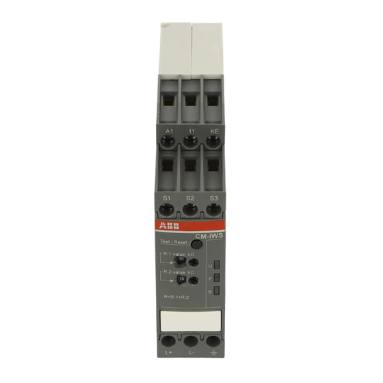
- Seite 5 Front views with operating controls Frontansichten mit Bedienelementen English Deutsch Indication of operational states with LEDs Betriebszustandsanzeige mit LEDs U: green LED - Status indication of control supply U: LED grün - Anzeige Steuerspeisespannung V Steuerspeisespannung liegt an voltage V Control supply voltage applied F: LED rot - Fehlermeldung F: red LED...
- Seite 10 V Funktionsdiagramme Deutsch Arbeitsweise a) Isolationswiderstandsüberwachung ohne Fehler speicherung, Das zu überwachende Netz wird an den Klemmen L (CM-IWS.2) Auto-Reset bzw. L+, L- (CM-IWS.1) angeschlossen. Das Erdpotential wird an b) Isolationswiderstandsüberwachung mit Fehlerspeicherung, manueller Reset den Klemmen und KE angeschlossen. Die Geräte arbeiten nach dem Ruhestromprinzip –...
- Seite 15 CM-IWS.2) IWN.1) test/reset IEC61557 8 CM-IWS.1 IT AC S1-S3 IEC61557 8 CM-IWS.2 IT AC test/reset S2-S3 CM-IWS.2 : 0-400V AC 45-65Hz CM-IWS.1 : 0-300V DC 0-250V AC 15-400Hz CM-IWS.1 CM-IWS.2 CM-IWS.1 CM-IWS.1 AC DC AC/DC...