Herunterladen Inhalt Inhalt Diese Seite drucken

Werbung

Verfügbare Sprachen
  • DE

Verfügbare Sprachen

  • DEUTSCH, seite 18
Fig.1 | Abb.1 | рис.1

Werbung

Inhaltsverzeichnis
loading

Inhaltszusammenfassung für TECNOINOX PPF8GG7

  • Seite 1 Fig.1 | Abb.1 | рис.1...
  • Seite 2 PPF8GG7 PF_8GG7 PF_8SGG7 PF_8G7 PF_8V7 PFP_8GG7 PF_12GG7 PFP_12GG7 PF_12G7 PF_12V7 PF_X12GG7 PF_X12GGE7 PF_X12G7 1200 1200 1200 1200 1200 1200 1200 Dimensioni esterne - External dimensions - Außenmaße - Dimensions extérieures - Dimensiones externas. (mm) Forno gas, Gas oven, Gasabackofen, Газовая печь, Four à gaz, Horno a 4.7 kW...
  • Seite 3 Fig.4 | Abb.4 | рис.4 Fig.5 | Abb.5 | рис.5 Fig.6 | Abb.6 | рис.6 Fig.7 | Abb.7 | рис.7 Fig.8 | Abb.8 | рис.8 Fig.9 | Abb.9 | рис.9 Fig.10 | Abb.10 | рис.10 Fig.11 | Abb.11 | рис.11 Fig.12 | Abb.12 | рис.12 Fig.13 | Abb.13 | рис.13 Fig.14 | Abb.14 | рис.14...
  • Seite 4 T1. Tabella ugelli – Düsentabelle - Nozzle table - Tableau des injecteurs - Tabla de los inyectores - Таблица форсунок Bruciatore (Brenner, burner, brûleur, quemador) ½ PIASTRA * PIASTRA * FORNO ** FORNO XL ** CATEGORIA P [mbar] Kat.;Cat. 1/100 mm 3.3 kW 4.5 kW 7.2 kW...
  • Seite 5 Cat. (kat.) Paese (land - country - pays - país) 20 mbar LU,PL I2E+ 20/25 mbar 28-30/37 mbar BE,LU I3B/P 28-30 mbar NL,NO,CY,MT II2E+3+ 20/25, 28-30/37 mbar BE,FR I3B/P 37 mbar II2ELL3B/P 20, 50 mbar II2H3+ 20, 28-30/37 mbar ES,GB,GR,IE,IT,PT,SK II2H3B/P 20, 28-30 mbar BG,DK,EE,FI,LV,LT,CZ,SE,SI...
  • Seite 6: Avvertenze Generali

    Le condutture di collegamento dal rubinetto al bruciatore sono in rame. La targhetta matricola in poliestere autoadesivo “T” fig.7 si trova dietro al Modello N°bruciatori Fornelli Forno pannello portacomandi (all'interno dell'apparecchio). PPF8GG7 Essa contiene i seguenti dati: per es.: 1×3.3kW+2×5.5kW + PF_8GG7 Modello PF_8GG7 1×7.2kW...
  • Seite 7: Controllo Della Pressione

    distanza minima di 80mm tra apparecchiatura ed eventuali pareti in Durante la prova di tenuta non usare fiamme libere! materiale infiammabile, divisori, mobili da cucina o apparecchiature adiacenti. Le superfici a contatto con l’apparecchiatura dovranno essere Il costruttore non si assume nessun impegno di garanzia per danni che rivestite in materiale isolante termico di tipo non combustibile.
  • Seite 8 Parte 2 – Trasformazione ed adattamento Per la trasformazione da un tipo di gas ad un altro, per es. da metano a GPL, si rende necessaria la sostituzione degli ugelli del bruciatore Si raccomanda che tutti i lavori relativi all’allacciamento, principale, del by-pass e del pilota.
  • Seite 9 Parte 3 - Uso Messa in funzione IMPORTANTE: CONSIGLI PER L'USO: Il forno alla prima accensione emana cattivi odori dovuti ai residui di È buona norma, per la riuscita dei vostri piatti, non introdurre mai le produzione quali grassi, oli e resina. pietanze a forno freddo, bensì...
  • Seite 10: Controllo Del Funzionamento

    Accensione e spegnimento del forno gas ACCENSIONE: Controllare attraverso il foro sul coperchio d’ispezione “I” (fig.5) l’avvenuta accensione. Aprire la porta del forno Posizionare successivamente la manopola sulla temperatura Premere e ruotare la manopola “O” (fig.4) della valvola termostatica desiderata. dalla posizione “...
  • Seite 11: Manutenzione

    Parte 4 – Manutenzione e pulizia Sostituzione di parti La sostituzione di parti difettose, deve essere eseguita esclusivamente I pezzi di ricambio sono da richiedere esclusivamente al costruttore da personale abilitato. Prima di iniziare qualsivoglia lavoro scollegare o da un rivenditore autorizzato. l’apparecchio dalla rete di distribuzione del gas e quella elettrica.
  • Seite 12: Installation

    II2H3+ gas ranges. are made of copper. The self-adhesive polyester data plate "T" (pic.7) is behind the control Model burners Rings Oven panel (inside the appliance). PPF8GG7 It contains the following information: PF_8GG7 1×3.3kW+2×5.5kW + 1×7.2kW Modell PF_8GG7 PF_8SGG7 4 × 7.2kW...
  • Seite 13 The appliance, and especially the cable, must not be installed near heat All the models have an equipotential earth terminal “ ” (pic.1) on the bottom. sources and the temperature of the place in which the appliance is installed must not exceed 50°C. The appliances featuring an electric oven have a hole for the cable “...
  • Seite 14 Part 2 Transformation and adaptation After each transformation or adaptation, the unit must undergo an To convert the appliance to another type of gas, e.g. from natural gas to operating test and the supplementary plate must be updated according LPG, the nozzles of the main burner, by-pass and pilot light have to be to the conversion or adaptation carried out.
  • Seite 15: Recommendations For Use

    Part 3 Working phase IMPORTANT: RECOMMENDATIONS FOR USE: The first time the oven is switched on, you will notice a bad smell due to For best results, you would always better put food in a hot oven. You production residues such as grease, oil and resin. ought to wait for the oven to reach the chosen temperature first.
  • Seite 16: Operational Checks

    Turning the gas oven on and off TURNING THE OVEN ON: Check the ignition through the hole in the inspection cover “I” (pic.5) Open the oven door Now set the knob to the desired temperature. Press and turn the knob “O” (pic.4) of the thermostatic valve from position “...
  • Seite 17: Maintenance

    Part 4 Maintenance and cleaning Replacing parts Only qualified personnel should replace faulty parts. Prior to If you remove the control panel, all the functional parts of the appliance commencing any kind of work, disconnect the unit from the gas will be easily accessible.
  • Seite 18: Gasherde Mit Backofen

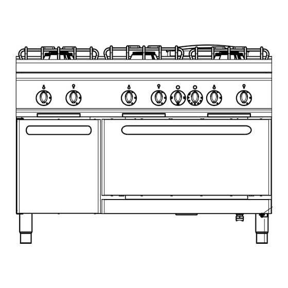
    Stahl, die Anschlussleitungen vom Hahn zum sich hinter der Bedienblende (im Geräteinneren). Brenner aus Kupfer. Es enthält folgende Daten: z.B.: Modell Brennerzahl Flammen Backofen Modell: PF_8GG7 PPF8GG7 Seriennummer: PF_8GG7 1×3.3kW+2×5.5kW + 1×7.2kW Kategorie: II2H3+ Baujahr: PF_8SGG7 4 × 7.2kW Nennwärmebelastung: [kW]...
  • Seite 19 Die Geräte mit Elektrobackofen sind mit einem Netzkabeleingang “ ” Für Deutschland (Abb.1) ausgestattet. Das Gerät kann sowohl freistehend als auch  DVGW-Arbeitsblatt G600 (TRGI) „Technische Regeln für gemeinsam mit anderen Geräten installiert werden. Gasinstallation“. Zwischen dem Gerät und eventuellen Wänden aus brennbarem ...
  • Seite 20 Teil 2 Umstellung und Anpassung Die Umstellung auf eine andere Gasart z.B. von Erdgas auf Flüssiggas Nach jeder Umstellung oder Anpassung ist eine Funktionskontrolle erfolgt durch den Austausch der Hauptbrenner-, Bypass- und vorzunehmen und das Zusatzschild entsprechend der erfolgten Zündbrennerdüsen. Alle Düsen sind mit einer Ziffer (Durchmesser in Umstellung bzw.
  • Seite 21 Teil 3 Gebrauch Inbetriebnahme WICHTIG: GEBRAUCHSEMPFEHLUNGEN Bei der ersten Inbetriebnahme erzeugt der Backofen einen Für ein gutes Gelingen Ihrer Speisen ist es empfehlenswert, diese nie in unangenehmen Geruch, der auf Produktionsrückstände, wie Fette, Öle den kalten Backofen einzuschieben. Die Speisen erst dann einschieben, und Harz zurückzuführen ist.
  • Seite 22 Ein- und Ausschalten des Gas-Backofens EINSCHALTEN: Die Flamme über das Inspektionsloch "I" (Abb.5) prüfen. Den Drehschalter auf die gewünschte Temperatur drehen. Die Backofentür öffnen. Den Drehschalter "0" (Abb. 4) des Thermostatventils drücken und Der Brenner ist mit einem Sicherheitsventil von “ ”...
  • Seite 23: Wartung

    Teil 4 Wartung und Reinigung Austausch von Teilen Der Austausch von defekten Teilen hat nur durch Fachpersonal zu Nach Abnahme der Bedienblende sind alle Funktionsteile des Gerätes erfolgen. Bevor jegliche Arbeit angefangen wird, ist grundsätzlich der leicht zugänglich. Gasabsperrhahn zu schließen. Die Ersatzteile ausschließlich beim Hersteller oder befugten Händler bestellen.
  • Seite 24: Характеристики Оборудования

    использованию N° Moдель Конфорки Печь относяться к газовым кухням категории II2H3+. форсунки Идентификационная табличка из самоклеющегося полиестра “T” PPF8GG7 (рис.7) находиться в задней части панели управления (внутри PF_8GG7 1×3.3kW+2×5.5kW + 1×7.2kW оборудования). PF_8SGG7 4 × 7.2kW Она содержит следующие данные: PF_8G7 1×3.3kW+2×5.5kW + 1×7.2kW...
  • Seite 25 Предписания и нормы учреждения выпускающего Оставлять минимальную дистанцию в 80mm. между  электроэнергию. оборудованием и возможной стенкой из невозгораемого материала, разделительными панелями, кухонной мебелью или близлежащим Действующие норма против несчастных случаев.  оборудованием.. Противопожарные предписания.  Поверхности, находящиеся в контакте с оборудованием должны Соответствующие...
  • Seite 26 Часть 2 Трансформация и адаптирование Для трансформации одного типа газа к другому, например от После каждой трансформации или адаптирования, подвергнуть метана к GPL необходимо заменить форсунки главной горелки, оборудование рабочему тестированию и обновить дополнительную обводной канал и пламя. Все форсунки обозначены номером, табличку, указывая...
  • Seite 27: Советы По Использованию

    Часть 3 Использование Запуск в работу ВНИМАНИЕ: СОВЕТЫ ПО ИСПОЛЬЗОВАНИЮ: При первом зажигании печь производит неприятные запахи, Следуя норме, для качественного приготовления ваших блюд , не производимые при сгорании остатков масел, смазки и резины. готовить ваши блюда в холодной печи, а дождаться разогрева печи Когда...
  • Seite 28: Инструкции Для Пользователя

    Включение и выключение газовой печи ВКЛЮЧЕНИЕ: Затем позиционировать ручку на желаемую тепературу. Открыть дверцу печи Нажать и повернуть ручку “O” (рис.4) термостатического горелка предлагается в комплекте с клапаном клапана с позиции “ ” на “ ” удерживая ее в нажатом безопасности...
  • Seite 29 Часть 4 Обслуживание и чистка Замена частей Замена поврежденных частей должна производиться только квалифицированным персоналом. Прежде чем начать любые работы необходимо отсоединить оборудование от сети распределения газа или электроэнергии. После снятия панели управления все рабочие части оборудования становяться легкодоступными. Запчасти должны запрашиваться непосредственно у производителя или у официального дистрибъютора. Чистка...
  • Seite 30: Conseils Généraux

    La présente notice d’installation se réfère se réfère aux cuisinières à Modèle brûleurs Feux vifs Four gaz, catégorie II2H3+. PPF8GG7 La plaque signalétique “T” (fig.7) en polyester autoadhésive se trouve PF_8GG7 1×3.3kW+2×5.5kW + 1×7.2kW derrière le panneau de commande (à l’intérieur de l’appareil). PF_8SGG7 4 ×...
  • Seite 31 ■ Normes CEI correspondantes. l’appareil et les parois réalisées en matériau inflammable, les cloisons, les meubles de cuisine ou d’autres appareils adjacents. Les surfaces en Il est recommandé d’installer l’appareil dans un local bien aéré ou sous contact avec les éléments sus-mentionnés devront être revêtues avec un une hotte aspirante afin d’évacuer les fumées ou les vapeurs qui se matériau isolant thermique de type non combustible.
  • Seite 32 Partie Transformation et adaptation ème Pour la transformation d’un type de gaz à un autre - par exemple pour sont fournis avec l’appareil dans un sachet. Après chaque changer du gaz naturel au GPL - il est nécessaire de remplacer les transformation ou adaptation, essayer les fonctions de l’appareil et injecteurs du brûleur principal, du by-pass et de la veilleuse.
  • Seite 33: Plaque Chauffante

    partie Utilisation ème Mise en service IMPORTANT: CONSEILS POUR L'EMPLOI: Lors de son premier allumage, le four émane de mauvaises odeurs dues Pour réussir vos plats, il est important de ne jamais introduire d’aliments aux substances, comme les graisses, les huiles et la résine, appliquées dans le four froid.
  • Seite 34: Instructions Pour L'usager

    Allumage et extinction du four à gaz ALLUMAGE: Contrôler à travers le regard “I” (fig.5) si la flamme est allumée. Positionner la manette du thermostat sur la température désirée. Ouvrir la porte du four Appuyer sur la manette “O” (fig.4) de la valve thermostatique et la Le brûleur est doté...
  • Seite 35: Maintenance Et Nettoyage

    partie Maintenance et nettoyage ème Remplacement des pièces Le remplacement des pièces défectueuses ne doit être effectué que par Toutes les parties servant au fonctionnement de l'appareil seront du personnel agréé. Avant de commencer toute opération, couper facilement accessibles après avoir enlevé le panneau de commande. l’arrivée du gaz à...
  • Seite 36: Instalación

    Este manual de instrucciones para la instalación y el uso se refiere a las Modelo quemadores Fuegos Horno cocinas a gas de la categoría II2H3+. PPF8GG7 La placa de características de poliéster autoadhesivo “T” (fig. 7) está PF_8GG7 1×3.3kW+2×5.5kW + 1×7.2kW situada detrás del panel de mandos (en el interior del aparato). PF_8SGG7 4 ×...
  • Seite 37 Se aconseja instalar el aparato en un ambiente bien ventilado o debajo El aparato puede instalarse solo o en batería. Respete una distancia de una campana extractora para la evacuación de los humos o vahos mínima de 80mm entre el aparato y las paredes eventuales de material producidos durante la cocción.
  • Seite 38 capítulo 2 Transformación y adaptación Después de cada transformación o adaptación debe efectuarse una Para la transformación a otro tipo de gas, por ejemplo de metano a GLP, prueba de las funciones del aparato y actualizar la placa suplementaria es necesario sustituir los inyectores del quemador principal, del by-pass de acuerdo con la transformación o adaptación efectuadas.
  • Seite 39 capítulo 3 Puesta en marcha IMPORTANTE: CONSEJOS PARA EL USO Al poner el horno en marcha por primera vez, podrían salir unos olores Es buena regla, para conseguir los mejores resultados con la comida, desagradables, debido a los residuos de producción, tales como grasas, nunca introducir los alimentos cuando el horno está...
  • Seite 40: Control Del Funcionamiento

    Encendido y apagamiento del horno a gas ENCENDIDO: Compruebe el encendido por el agujero posicionado encima la tapa “I” (fig.5). Abra la puerta del horno. Coloque el pomo del termostato en la temperatura deseada. Oprima y ruede el pomo “O” (fig.4) de la válvula termostática desde la posición “...
  • Seite 41: Mantenimiento Y Limpieza

    capítulo 4 Mantenimiento y limpieza Sustitución de piezas Solamente el personal experto puede sustituir las piezas eventualmente defectuosas. Desconecte el aparato de la red de suministro de gas y electricidad antes de comenzar cualquier trabajo. Quite el tablero de mandos, asì que es más fácil acceder a todas las piezas funcionales del aparato. Los recambios se deben pedir únicamente al fabricante o a un distribuidor autorizado.

Inhaltsverzeichnis