System Sensor 2351TEM Installations- Und Wartungsanleitung
Verfügbare Sprachen
Verfügbare Sprachen
2351TEM
B401x
57mm
70°C
-30°C
105 g
Figure 1: Base Terminal Wiring
V-
2
3
-
1
+
4
5
R
V+
Figure 2: Tamper Resist Feature
PLASTIC LEVER
TO REMOVE, USE A SMALL
SCREWDRIVER TO PUSH
PLASTIC IN THE DIRECTION
OF THE ARROW, WHILST
ROTATING THE SENSOR
ANTI-CLOCKWISE
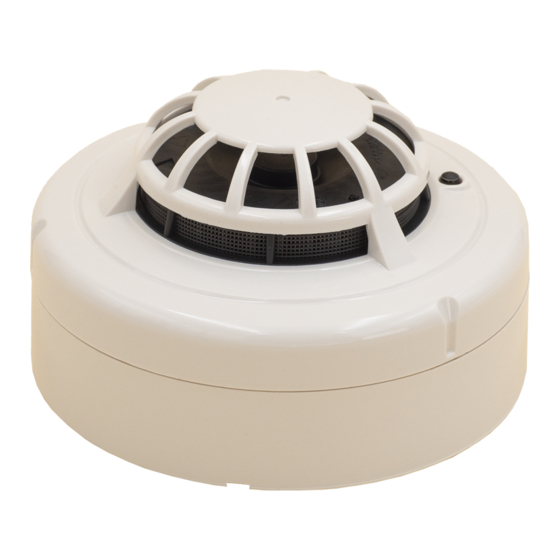
Figure 3: 2351TEM Optical-Thermal Smoke Detector
0832 05
DETECTOR
COVER
2351TEM
DoP Ref:
0832-CPD-0060
EN54-7: 2000
EN54-5: Class A1R
System Sensor Europe
Life Safety Distribution
GmbH
Javastrasse 2
THERMISTOR
8604 Hegnau
Switzerland
SENSING
CHAMBER
ENGLISH
INSTALLATION AND MAINTENANCE INSTRUCTIONS
GENERAL DESCRIPTION
Model 2351TEM photo-thermal fire sensors combine a state of the art optical sensing chamber
with a thermistor to offer greater flexibility and higher immunity to nuisance alarms. The ability
to plug these sensors into a variety of base options extends panel compatibility and application
flexibility. These sensors are designed to provide open area protection and are only to
be used with compatible control panels.
A bicolour LED on each sensor lights red to provide a local visible alarm indication, flashes
yellow to indicate a chamber fault or drift compensation limit reached, and may also be set to
flash green to indicate correct operation of the sensor. Remote LED annunciator capability is
available as an optional accessory wired to the standard base terminals. These sensors also
have a latching alarm feature. The alarm can be reset only by a momentary power interruption.
Three sensitivity settings are available on the 2351TEM: high, medium and low. These
sensitivities are set using a dedicated tool available from System Sensor. This tool may also be
used to access operating data from the sensor .
D300-04-01
I 56- 1721- 021
102 mm
V-
SHORTING
SPRING
NOTE: WHEN A BASE FITTED WITH A
RESISTOR (R) - BETWEEN TERMINALS
4 AND 5 - IS USED, THE WIRING SHOULD
FOLLOW THE DASHED LINE.
A SCHOTTKY DIODE
CONNECTED BETWEEN
TERMINALS 2 AND 3 DOES
NOT AFFECT BASE WIRING.
V+
TO ACTIVATE, BREAK TAB ON PLASTIC
LEVER AT DOTTED LINE BY TWISTING
TOWARD CENTRE OF BASE
SCREEN
Pittway Tecnologica S.r.l. Via Caboto 19/3, 34147 TRIESTE, Italy
SPECIFICATIONS
Supply voltage
Air velocity
Humidity
Quiescent current
Maximum alarm current
Latching alarm
This sensor has been independently tested and certified to EN54-7, EN54-5 Class A1R and
CEA 4021.
Note: Do not install in locations where the normal ambient temperature range extends
beyond 0°C to 50°C for extended periods, particularly if icing or condensation may be
expected.
BASE MOUNTING AND WIRING INSTRUCTIONS
Verify that the sensor base supplied is compatible with the system control panel.
400 series bases may be mounted to standard electrical junction boxes with 50-60 mm centre
fixings.
See figure 1 for terminal connections on standard bases. If relay bases are to be used, please
refer to the relevant base instructions.
Notes:
1.
Series 300 sensors are polarity conscious, and must be wired as indicated.
2.
Do not loop wire under terminals: break the wire run to ensure supervision of connections.
3.
All wiring must conform to applicable local and national codes and regulations.
Each 400 series base is fitted with a shorting spring, which may be used to connect across
terminals 2 and 3 to permit loop wiring to be checked before installation of sensor heads. This
spring automatically disengages when the sensor is fitted into the base.
Remove power from sensor monitoring circuits before installing sensors.
SENSOR INSTALLATION
1.
Insert the sensor into the base and rotate it clockwise until it locks into place.
2.
After all sensors have been installed, apply power to the sensor monitoring circuits.
3.
Test the sensor as described under TESTING.
4.
Reset the sensor at the system control panel.
Tamper-resistance
The sensor bases include a feature that, when activated, prevents removal of the sensor
without the use of a tool. See figure 2 for details .
Dust covers are fitted to the sensors to help protect units during shipment and
when first installed. They are not intended to provide complete protection against
contamination; therefore sensors should be removed before beginning construction,
major re-decoration or other dust producing activity. Dust covers must be removed
before the system can be made operational.
TESTING
Sensors must be tested after installation and following periodic maintenance. Disable the zone
or system undergoing maintenance to prevent unwanted alarms. Test the sensor as follows:
Smoke Method
1.
Using generated smoke, or synthetic smoke aerosol from an approved manufacturer
such as No Climb Products Ltd, subject the sensor to controlled amounts of smoke in
accordance with local codes of practice and manufacturer recommendations.
2.
The red LED on the sensor should latch into alarm within 40 seconds, and the control
panel should activate into alarm.
Direct Heat Method
1.
Use either a specialised tool such as supplied by No Climb Products Limited, or a
hairdryer of 1000 to 1500 Watts.
2.
Direct the heat towards the sensor thermistor from its side. Hold the heat source about
15cm away from the detector to prevent damage during the test.
3.
The red LED on the detector should latch into alarm within 40 seconds, and the control
panel should activate into alarm.
Laser Test Tool Method (Model No. S300RTU)
Note: this method does not carry out a complete functional test of the sensor.
1.
Align the flashing red spot produced by the laser beam with the LED on the sensor.
2.
Provided the sensor has not reached its drift compensation limit, it should latch into alarm
within a few seconds, and the control panel should activate into alarm.
The S300RTU test tool is a Class II laser product. Do not direct the beam towards a
person's face or eyes
A fter completion of all tests notify the proper authorities that the fire system is operational.
MAINTENANCE
Before cleaning, disable the system to prevent unwanted alarms.
1.
Remove the sensor to be cleaned from the system.
2.
Gently release the 4 cover removal tabs that secure the cover in place by inserting a
small screwdriver into the recess, and gently levering outwards, and remove the sensor
cover.
3.
Vacuum the outside of the screen carefully without removing it.
4.
Carefully remove the screen from the sensing chamber.
5.
Use a vacuum cleaner and/or clean, compressed air to remove dust and debris from the
sensing chamber and the inside of the screen.
6.
Re-install the screen by aligning the arrow moulded on it with the arrow on the sensing
chamber. Slide the screen over the chamber, applying gentle pressure to secure it in
place.
7.
Reinstall the sensor cover. Align the LED with the cover assembly and snap the cover
into place, ensuring that all the cover removal tabs are correctly engaged.
8.
When all the sensors have been cleaned, restore power to the circuit and test the sensor
as described in TESTING above.
WARNING - LIMITATIONS OF SMOKE SENSORS
Smoke sensors must be used in conjunction with compatible equipment.
Smoke sensors will not sense fires which start where smoke does not reach the sensors.
A sensor may not detect a fire developing on another level of a building.
Smoke sensors also have sensing limitations. Consideration must be made of the environment
when selecting fire sensors.
Smoke sensors cannot last forever. Smoke sensors contain electronic parts. Even though
sensors are made to last over 10 years, any of these parts could fail at any time. Therefore, test
your smoke detection system at least semi-annually. Clean and take care of your smoke sensors
regularly. Taking care of the fire detection system you have installed will significantly reduce your
product liability risks.
8 - 30VDC
20m/s (4000 ft/min)
5 - 95%RH (non-condensing)
65µA Typical
80mA (Limited by panel or base resistance)
Reset by momentary power interruption.
WARNING
CAUTION
CAUTION
I56-1721-021

Verwandte Anleitungen für System Sensor 2351TEM


Inhaltszusammenfassung für System Sensor 2351TEM
- Seite 4 Für den optischen Rauchmelder Typ 2351TEM sind drei unterschiedliche Meldeempfindlichkeiten ausfallen. Testen Sie deshalb mindestens halbjährlich Ihr Meldersystem. Reinigen und inspizieren einstellbar: hoch, mittel und niedrig. Mit einem speziellen System Sensor Werkzeug können diese Sie die Brandmelder regelmäßig. Inspektionen des Brandmeldesystems reduzieren erheblich das Einstellungen durchgeführt und auch auf die Betriebsdaten des Brandmelders zugegriffen werden.