Herunterladen Inhalt Inhalt Diese Seite drucken

Werbung

Verfügbare Sprachen
  • DE

Verfügbare Sprachen

  • DEUTSCH, seite 25
NEDERLANDS
Conceptronic CB100S24S & CB100S48S
Snelstartgids
Gefeliciteerd met uw nieuwe
Conceptronic 24/48-poorts 10/100 Mbps Smart switch.
In deze snelstartgids vindt u stap-voor-stap instructies voor de installatie van de Conceptronic 24/48-
poorts 10/100 Mbps Smart switch.
Bij problemen kunt u het beste naar onze support-site gaan (www.conceptronic.net - klik op 'Support').
Daar vindt u een database met veel gestelde vragen (FAQ).
Als u een vraag over dit product heeft die niet op onze website wordt beantwoord, kunt u ons gerust e-
mailen op support@conceptronic.net.
Ga voor meer informatie over Conceptronic producten naar de Conceptronic website:
www.conceptronic.net.
1. Inhoud verpakking
U vindt de volgende items in de verpakking van de Conceptronic Web Smart switch:
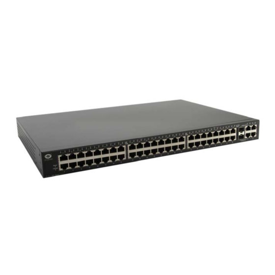
• Conceptronic 24/48-poorts 10/100 Mbps Smart Switch (in deze snelstartgids aangeduid als 'de switch').
• Netsnoer
• DCE RS-232 consolekabel
• Switch montageset (2 hoeksteunen met schroeven)
• 4 rubberen voetjes
• Product-cd
• Deze snelstartgids
1

Werbung

Inhaltsverzeichnis
loading

Inhaltszusammenfassung für Conceptronic CB100S48S

  • Seite 1 In deze snelstartgids vindt u stap-voor-stap instructies voor de installatie van de Conceptronic 24/48- poorts 10/100 Mbps Smart switch. Bij problemen kunt u het beste naar onze support-site gaan (www.conceptronic.net - klik op 'Support'). Daar vindt u een database met veel gestelde vragen (FAQ).
  • Seite 2 NEDERLANDS 2. Aansluitcomponenten Hieronder ziet u een korte beschrijving van de aansluitcomponenten van de switch. CB100S24S • 24x 10/100 Mbps BASE-T poorten. • 2x SFP-poorten, rechter zijkant.** • 4x 1000 BASE-T poorten, rechter zijkant.** • 1x DCE RS-232 DB-9 poort (vrouwelijk). •...
  • Seite 3 DCE RS-232 DB-9 poort (vrouwelijk), achterkant van de switch. • 1x Lichtnetaansluiting, achterkant. • Aan/uit- en console-lampjes. • Link/ACT/snelheid-lampjes voor elke poort. [ CB100S48S ] Wanneer de SFP-transceiver een verbinding legt, wordt de bijbehorende 10/100/1000 BASE-T poort van de switch uitgeschakeld.
  • Seite 4 NEDERLANDS 3. Switch installeren 3.1 Switch installeren voor gebruik op bureau of boekenplank Als u de switch op een bureau of plank wilt zetten, plakt u de meegeleverde rubberen voetjes op de vier hoeken aan de onderkant van de switch. Dit is nodig om voldoende ventilatieruimte te creëren tussen de switch en het oppervlak waarop deze is geplaatst.
  • Seite 5 NEDERLANDS Let op: Als u een systeem in een rack zet, kan het rack omvallen als er geen stabilisators aan de voorkant en de zijkant zijn gemonteerd; dit kan tot schade leiden en onder bepaalde omstandigheden lichamelijk letsel veroorzaken. Plaats dus altijd eerst de stabilisators voordat u componenten in het rack zet.
  • Seite 6 NEDERLANDS 4. De SFP-poorten installeren De Managed Web Smart Switches van Conceptronic zijn uitgerust met SFP (Small Form Factor Portable) poorten waarop een transceiver voor optische glasvezelkabel kan worden aangesloten om een (lange- afstand) gigabitverbinding met andere netwerkapparaten te realiseren.
  • Seite 7 NEDERLANDS 5. Switch aansluiten Switch naar End Node "End nodes" zijn onder meer pc's met een 10, 100 or 1000 Mbps RJ 45 Ethernet/Fast Ethernet netwerkkaart (NIC) en de meeste routers. End nodes worden op de switch aangesloten via een UTP/STP kabel, categorie 3, 4 of 5 (twisted-pair).
  • Seite 8 NEDERLANDS Switch naar hub of andere switch Deze verbindingen kunnen op verschillende manieren worden gerealiseerd met normale kabels: • Een 10BASE-T hub of switch kan op de switch worden aangesloten via een UTP/STP kabel, categorie 3, 4 of 5 (twisted-pair). •...
  • Seite 9: Package Contents

    Congratulations on the purchase of your Conceptronic 24/48 Ports 10/100Mbps Smart switch . This Quick Installation Guide gives you a step-by-step explanation of how to install the Conceptronic 24/48 Ports 10/100Mbps Smart switch. When problems occur, we advise you to go to our support-site (go to www.conceptronic.net and click ‘Support’.
  • Seite 10 ENGLISH 2. Switch connection components Below you will find a short description of the connection components of the switches. CB100S24S • 24x 10/100Mbps BASE-T ports. • 2x SFP ports, located on the right side. ** • 4x 1000BASE-T ports, located on the right side. ** •...
  • Seite 11 • 1x AC Power connection, located on the backside of the switch. • Power & Console LEDs. • Link/Act/Speed LEDs for each port. [ CB100S48S ] When the SFP transceiver acquires a link, the associated integrated 10/100/1000BASE-T port is disabled.
  • Seite 12 ENGLISH 3. Switch installation 3.1 Installing the switch for desktop or shelf use When installing the switch on a desktop or shelf, the rubber feet included with the switch should be attached to the bottom. Attach these rubber feet on the bottom at each corner of the switch. This will allow enough ventilation space between the switch and the surface the switch is placed on.
  • Seite 13 ENGLISH Warning: Installing systems in a rack without the front and side stabilizers installed could cause the rack to tip over, potentially resulting in bodily injury under certain circumstances. Therefore, always install the stabilizers before installing components in the rack. After installing components in a rack, do not pull more than one component out of the rack on its slide assemblies at one time.
  • Seite 14 ENGLISH 4. Installing the SFP ports The Conceptronic Managed Web Smart Switches are equipped with SFP (Small Form Factor Portable) ports, which can be used with fiber-optical transceiver cabling, in order to uplink various other networking devices for a gigabit link that may span great distances.
  • Seite 15: Connecting The Switch

    ENGLISH 5. Connecting the switch 5.1 Switch to End Node End nodes include PCs outfitted with a 10, 100 or 1000 Mbps RJ 45 Ethernet/Fast Ethernet Network Interface Card (NIC) and most routers. An end node can be connected to the switch via a twisted-pair Category 3, 4, or 5 UTP/STP cable.
  • Seite 16 ENGLISH 5.2 Switch to hub or other switch These connections can be accomplished in a number of ways using a normal cable: • A 10BASE-T hub or switch can be connected to the switch via a twisted-pair Category 3, 4 or 5 UTP/STP cable.
  • Seite 17: Guía De Instalación Rápida

    24/48 puertos de Conceptronic. Si se producen problemas, le aconsejamos que consulte a nuestro servicio técnico (en www.conceptronic.net y haga clic en “Support”. Aquí encontrará la base de datos de las preguntas más frecuentes o FAQ). Si tiene otras preguntas sobre su producto y no las encuentra en nuestro sitio web, póngase en contacto con nosotros por correo electrónico: apoyo@conceptronic.net.
  • Seite 18 ESPAÑOL 2. Componentes de conexión del switch A continuación enumeramos brevemente los componentes de conexión de los switches. CB100S24S • 24 puertos BASE-T de 10/100Mbps • 2 puertos SFP, ubicados en la parte derecha** • 4 puertos 1000BASE-T, ubicados en la parte derecha** •...
  • Seite 19 AC, ubicada en la parte trasera del switch • LEDs de encendido y consola • LEDs Link/Act/Velocidad para cada puerto [ CB100S48S ] Cuando el transceptor SFP incorpore un enlace, el puerto 10/100/1000BASE-T asociado integrado quedará desactivado.
  • Seite 20 ESPAÑOL 3. Instalación del switch 3.1 Instalación del switch para su uso en un escritorio o en un estante Cuando instale el switch en un escritorio o en un estante, deberá colocar y adherir las peanas de goma que incluye el producto en la parte inferior de cada esquina del switch. Así...
  • Seite 21 ESPAÑOL Atención: Instalar sistemas en un rack sin haber montado primero los estabilizadores frontal y lateral podría hacer que el rack volcase y provocar lesiones en determinadas situaciones. Por tanto, monte siempre los estabilizadores antes de instalar componentes en un rack. Una vez instalados los componentes, no saque del rack más de un componente al mismo tiempo por las juntas deslizantes.
  • Seite 22 ESPAÑOL 4. Instalación de los puertos SFP Los conectores Web Smart Switches de Conceptronic están equipados con puertos SFP (Small Form Factor Portable), que pueden utilizarse con cableado de fibra óptica del transceptor para realizar enlaces ascendentes con otros dispositivos de red y obtener un enlace gigabit capaz de abarcar grandes distancias.
  • Seite 23 ESPAÑOL 5. Conectar el switch 5.1 Conectar el nodo final al switch Entre los nodos finales se incluyen PCs equipados con una tarjeta de interfaz de red (NIC) RJ 45 Ethernet/Fast Ethernet de 10, 100 o 1000 Mbps y la mayoría de routers. Un nodo final puede conectarse al switch mediante un cable UTP/STP de par trenzado de categoría 3, 4 o 5.
  • Seite 24 ESPAÑOL 5.2 Conexión a un hub o a otro switch Pueden llevarse a cabo las conexiones siguientes de diversas maneras utilizando un cable normal: • Un hub o switch 10BASE-T puede conectarse al switch mediante un cable UTP/STP de par trenzado de categoría 3, 4 o 5.
  • Seite 25 1. Packungsinhalt In der Verpackung des Conceptronic Web Smart Switches ist Folgendes enthalten: • Conceptronic 10/100Mbps Smart Switch mit 24/48 Ports (in dieser Anleitung als ‚Switch’ bezeichnet) • Wechselstromkabel • DCE RS-232-Konsolenkabel • Montagesatz für Switch (2 Halter mit Schrauben) •...
  • Seite 26: Anschlusskomponenten Des Switches

    DEUTSCH 2. Anschlusskomponenten des Switches Es folgt eine kurze Beschreibung der Anschlusskomponenten des Switches. CB100S24S • 24x 10/100Mbps BASE-T-Ports • 2x SFP-Ports, auf der rechten Seite ** • 4x 1000BASE-T-Ports, auf der rechten Seite ** • 1x Buchse DCE RS-232 DB-9-Konsolen-Port •...
  • Seite 27 Buchse DCE RS -232 DB-9-Konsolen-Port, auf der Rückseite des Switches • 1x Wechselstromanschluss, auf der Rückseite des Switches • Power- und Konsolen-LED-Anzeigen • Link/Act/Speed-LED-Anzeigen für jeden Port [ CB100S48S ] Wenn der SFP-Transceiver eine Verbindung unterhält, ist der zugehörige integrierte 10/100/1000BASE-T-Port deaktiviert.
  • Seite 28: Installation Des Switches

    DEUTSCH 3. Installation des Switches 3.1 Installation des Switches auf einem Schreibtisch oder Regal Bei der Installation des Switches auf einem Schreibtisch oder Regal müssen die im Lieferumfang enthaltenen Gummifüße an der Unterseite des Switches befestigt werden. Bringen Sie diese Gummifüße auf der Unterseite des Switches in jeder Ecke an.
  • Seite 29 DEUTSCH Warnung: Der Einbau eines Switches in ein Rack, ohne dazu die vorderen und seitlichen Stabilisatoren anzubringen, könnte dazu führen, dass das Rack umkippt, was unter gewissen Umständen Körperverletzungen zur Folge haben kann. Bringen Sie deshalb immer die Stabilisatoren an, bevor Sie Komponenten im Rack installieren.
  • Seite 30: Installation Der Sfp-Ports

    DEUTSCH 4. Installation der SFP-Ports Die Conceptronic Managed Web Smart Switches sind mit SFP-(Small Form Factor Portable – kleiner Formfaktor, tragbar) Ports ausgerüstet, die für die Verbindung verschiedener anderer Netzwerkgeräte für einen Gigabit-Link mit großen Distanzen mit Glasfaser-Transceiver-Kabeln verwendet werden können.
  • Seite 31: Anschluss Des Switches

    DEUTSCH 5. Anschluss des Switches 5.1 Switch an Endknoten Zu Endknoten gehören PCs, die mit einer 10, 100 oder 1000 Mbps RJ 45 Ethernet/Fast Ethernet Netwerkschnittstellenkarte (NIC) ausgerüstet, sind und die meisten Router. Ein Endknoten kann mit einem verdrillten UTP-/STP-Kabel der Kategorie 3, 4 oder 5 an den Switch angeschlossen werden. Der Endknoten sollte an einem der Ports des Switches angeschlossen werden.
  • Seite 32 DEUTSCH 5.2 Switch an Hub oder an anderen Switch Diese Verbindungen können auf verschiedene Arten mit einem normalen Kabel hergestellt werden: • Ein 10BASE-T-Hub oder -Switch kann mit einem verdrillten UTP-/STP-Kabel der Kategorie 3, 4 oder 5 an den Switch angeschlossen werden. •...
  • Seite 33: Guide D'installation Rapide

    10/100 Mbps à 24/48 ports de Conceptronic. En cas de problème, nous vous conseillons de consulter notre site web de support technique (en allant sur www.conceptronic.net et en cliquant sur « Support »). Vous y trouverez les réponses aux questions les plus fréquentes (FAQ).
  • Seite 34 FRANÇAIS 2. Éléments de branchement du commutateur Vous trouverez ci-dessous une brève description des éléments de branchement du commutateur. CB100S24S • 24 ports BASE-T à 10/100 Mbps. • 2 ports SFP situés sur le côté droit. ** • 4 ports 1000BASE-T situés sur le côté droit. ** •...
  • Seite 35 • 1 alimentation électrique CA située à l’arrière du commutateur. • voyants d’alimentation et de la console. • voyant Connexion/Actif/Vitesse de chaque port. [ CB100S48S ] Quand le transcepteur SFP détecte une connexion, le port intégré 10/100/1000BASE-T associé est désactivé.
  • Seite 36 FRANÇAIS 3. Installation du commutateur 3.1 Installation du commutateur sur un bureau ou une étagère Pour installer le commutateur sur un bureau ou une étagère, les pieds en caoutchouc fournis avec ce dernier doivent être posés sur la base. Collez ces pieds en caoutchouc à chaque angle du commutateur. Cela créera un espace suffisant pour une bonne ventilation entre le commutateur et la surface sur laquelle il repose.
  • Seite 37 FRANÇAIS Attention : le fait d’installer un dispositif dans un rack sans avoir monté les stabilisateurs avant et arrière peut faire basculer l’ensemble et, dans certaines circonstances, supposer un danger de blessures. Par conséquent, posez toujours les stabilisateurs avant d’insérer tout dispositif dans un rack.
  • Seite 38 FRANÇAIS 4. Installation des ports SFP Les connecteurs Smart Web de Conceptronic sont équipés de ports SFP (Small Form Factor Portable) qui peuvent être utilisés avec un câblage de transmission-réception à fibre optique afin de créer une liaison montante avec d’autres appareils connectés au réseau pour une connexion de haute capacité pouvant supporter de grandes distances.
  • Seite 39 FRANÇAIS 5. Branchement du commutateur 5.1 Connexion à un End node (point de départ et d’arrivée des données) Les End nodes supposent des connexions vers PC à travers une carte interface réseau (NIC) RJ 45 Ethernet/Fast Ethernet de 10, 100 ou 1000 Mbps et à travers la plupart des routers. Un End node peut être connecté...
  • Seite 40 FRANÇAIS 5.2 Connexion à un hub ou à un autre commutateur Ces connections peuvent être obtenues de plusieurs manières en utilisant un câble normal : • Un hub ou un commutateur 10BASE-T peut être connecté à l’appareil à l’aide d’un câble à paire torsadée de catégorie 3, 4 ou 5 UTP/STP.
  • Seite 41: Contenuto Della Confezione

    In caso di domande e dubbi di altra natura riguardanti il prodotto e che non appariranno nel nostro sito web, potete contattarci via e-mail al seguente indirizzo: support@conceptronic.net Per maggiori informazioni sui prodotti di Conceptronic potete consultare la pagina web di Conceptronic: www.conceptronic.net 1. Contenuto della confezione...
  • Seite 42 ITALIANO 2. Componenti di connessione Switch Qui di seguito appare una breve descrizione dei componenti di connessione dello switch. CB100S24S • 24 porte BASE-T 10/100Mbps • 2 porte SFP, poste sul lato destro. ** • 4 porte 1000BASE-T, poste sul lato destro ** •...
  • Seite 43 AC, posta nella zona posteriore dello switch • LED di alimentazione e di console • LED di connessione (Link), attività (Act) e velocità (Speed) per ogni porta [ CB100S48S ] Quando il ricetrasmettitore SFP trova una connessione, la porta 10/100/1000BASE-T integrata a esso associata viene disattivata.
  • Seite 44 ITALIANO 3. Come installare lo Switch 3.1 Come installare lo switch da usare su una scrivania o su un ripiano Quando lo switch viene installato per essere usato su una scrivania o su un ripiano, è necessario applicare nella zona inferiore i piedini in gomma acclusi, in ognuno dei quattro angoli. In questo modo verrà...
  • Seite 45 ITALIANO Avviso: Se si installano diversi sistemi in un rack senza i moduli di stabilizzazione frontale e laterale il rack potrebbe rovesciarsi. Per questo motivo è sempre necessario collocare tali moduli prima di installare i componenti nel rack. Dopo aver installato i componenti in un rack, non tirare fuori dal rack più...
  • Seite 46 4. Come installare le porte SFP Gli Smart Switch gestiti via web di Conceptronic sono dotati di porte SFP (Small Form Factor Portable), che si possono usare con ricetrasmettitori via cavo a fibre ottiche, per poter realizzare uplink con diversi dispositivi di rete per una connessione gigabit che può...
  • Seite 47 ITALIANO 5. Come collegare lo switch 5.1 Switch collegato a End Node Gli end node comprendono PC dotati di una scheda di interfaccia di rete (NIC) RJ 45 Ethernet/Fast Ethernet da 10, 100 o 1000 Mbps e la maggior parte dei router. Un end node si può collegare allo switch attraverso un doppino intrecciato categoria 3, 4, o 5 UTP/STP.
  • Seite 48 ITALIANO 5.2 Switch collegato a un hub o a un altro switch Questo tipo di connessioni si può realizzare in diverse maniere usando un cavo normale: • Un hub o un switch 10BASE-T si può collegare allo switch attraverso un doppino intrecciato categoria 3, 4 o 5 UTP/STP.
  • Seite 49: Conteúdo Da Embalagem

    24/48 portas a 10/100 Mbps da Conceptronic. Quando tiver algum problema, aconselhamo-lo a consultar a nossa página de suporte (vá a www.conceptronic.net) e clicar em ‘Support’ (Suporte). Aí vai encontrar a Base de Dados das Perguntas Mais Frequentes.
  • Seite 50 PORTUGUÊS 2. Componentes de ligação do comutador A seguir vai encontrar uma pequena descrição dos componentes de ligação do comutador. CB100S24S • 24 portas BASE-T 10/100 Mbps. • 2 portas SFP localizadas do lado direito. ** • 4 portas BASE-T 1000 localizadas do lado direito. ** •...
  • Seite 51 CA, localizada na parte de trás do comutador. • LEDs da consola e de alimentação. • LEDs de Ligação/ Activo/ Velocidade para cada porta. [ CB100S48S ] Quando o transmissor-receptor SFP adquirir uma ligação, a porta integrada BASE-T 10/100/1000 associada é desactivada.
  • Seite 52 PORTUGUÊS 3. Instalação do comutador 3.1 Instalação do comutador numa secretária ou numa estante Quando instalar o comutador numa secretária ou numa estante, os pés de borracha incluídos no mesmo devem ser fixados à parte de baixo. Fixe estes pés de borracha em todos os cantos da parte de baixo do comutador.
  • Seite 53 PORTUGUÊS Atenção: Instalar os sistemas num bastidor sem ter os estabilizadores da frente e do lado instalados pode fazer com que o bastidor vire, podendo resultar em danos corporais em certas circunstâncias. Por isso, instale sempre os estabilizadores antes de instalar os componentes no bastidor.
  • Seite 54 PORTUGUÊS 4. Instalação das portas SFP Os comutadores inteligentes geridos pela web da Conceptronic estão equipados com portas SFP (Small Form Factor Portable) que podem ser usadas com cabos de transmissor-receptor de fibra óptica de modo a ligar outros dispositivos de rede a uma rede gigabite que pode cobrir grandes distâncias.
  • Seite 55 PORTUGUÊS 5. Ligar o comutador 5.1 O comutador a um terminal Um terminal pode ser um PC equipado com Ethernet RJ 45 a 10, 100 ou 1000 Mbps/ placa de interface de rede Fast Ethernet (NIC) e a maior parte dos routers. Um terminal pode ser ligado ao comutador através de um cabo cruzado UTP/STP de categoria 3, 4 ou 5.
  • Seite 56 PORTUGUÊS 5.2 O comutador a um hub ou a outro comutador Estas ligações podem ser conseguidas de inúmeras maneiras usando um cabo normal: • Um hub 10BASE-T ou um comutador podem ser ligados ao comutador através de um cabo cruzado UTP/STP de categoria 3, 4 ou 5.
  • Seite 57: Gyorstelepítési Útmutató

    Gyorstelepítési útmutató Köszönjük, hogy a Conceptronic 24/48 portos 10/100 Mb/s intelligens kapcsolóját választotta. Ez a gyorstelepítési útmutató lépésről-lépésre elmagyarázza, miként kell a Conceptronic 24/48 portos 10/100 Mb/s intelligens kapcsolóját telepítenie. Ha probléma jelentkeznek, azt tanácsoljuk, hogy keresse fel terméktámogatást gyújtó webhelyünket (látogasson el a www.conceptronic.net honlapra, majd ott kattintson a „Support”-ra).
  • Seite 58 MAGYAR 2. A kapcsoló csatlakoztatásához szükséges alkatrészek Alábbiakban ismertetjük röviden a kapcsolók csatlakoztatására szolgáló alkatrészeket. CB100S24S • 24x 10/100 Mb/s BASE-T port. • 2x SFP-port, a jobb oldalon.** • 4x 1000BASE-T port, a jobb oldalon.** • 1x Dugaszhüvelyes DCE RS-232 DB-9-es konzolport. •...
  • Seite 59 • 1x Váltakozó áramú hálózati csatlakozó, a kapcsoló hátoldalán. • Az áramellátást jelző és konzol-LED-ek. • Kapcsolat-/tevékenység-/sebességjelző LED-ek minden egyes porthoz. [ CB100S48S ] Ha az SFP adó-vevő kapcsolatot alakít ki, a hozzá tartozó, integrált 10/100/1000BASE-T port le van tiltva.
  • Seite 60 MAGYAR 3. A kapcsoló telepítése 3.1 Kapcsoló telepítése asztali vagy polcos alkalmazáskor A kapcsolónak asztalra vagy polcra történő telepítésekor a kapcsolóhoz mellékelt gumilábakat a berendezés aljára kell rögzíteni. Ezeket a gumilábakat a kapcsolónak mind a négy sarkán alul rögzítse. Ezzel elegendő teret biztosít a szellőzéshez a kapcsoló és a között a felület között, amelyen a kapcsolót elhelyezik.
  • Seite 61 MAGYAR Figyelem! Ha a különböző rendszereket elülső és oldalsó stabilizátorok felszerelése nélkül telepítik állványkeretre, akkor az állványkeret felbillenhet, ezzel pedig esetleg testi sérülést okozhat bizonyos feltételek mellett. Ennélfogva a stabilizátorokat mindig még azelőtt fel kell szerelni, hogy az adott alkatrészeket beépítenék a keretre. Az alkatrészeknek egy adott keretre történő beépítése után soha ne húzzon ki —...
  • Seite 62 MAGYAR 4. Az SFP portok telepítése A Conceptronic irányított webintelligens kapcsolói SFP- (kis formatényezős, hordozható) portokkal vannak felszerelve, amelyek az adó-vevőhöz tartozó, száloptikás kábelezéssel együtt használhatók, így különböző, további hálózati eszközök is csatlakoztathatók felfelé az esetleg nagyobb távolságokat lefedő, gigabites kapcsolat kialakítása érdekében.
  • Seite 63 MAGYAR 5. A kapcsoló csatlakoztatása 5.1 Kapcsoló csatlakoztatása végső csomóponthoz A végső csomópontokhoz hozzátartoznak a 10, 100 vagy 1000 Mb/s RJ 45-ös Ethernet/Fast Ethernet hálózati illesztőkártyával (NIC) felszerelt PC-k, valamint a legtöbb útválasztó is. Az adott végső csomópont a kapcsolóhoz sodrott érpárú, 3-, 4-, illetve 5-ös kategóriájú UTP-/STP-kábelen keresztül csatlakoztatható.
  • Seite 64 MAGYAR 5.2 Kapcsoló csatlakoztatása hubhoz vagy másik kapcsolóhoz Ezek a csatlakozások — normál kábel alkalmazásával — sokféleképpen kialakíthatók: • 10BASE-T hub vagy kapcsoló csatlakoztatható a kapcsolóhoz, ha sodrott érpárú. 3-, 4- vagy 5-ös kategóriájú UTP-/STP-kábelt alkalmaznak. • 100BASE-TX hub vagy kapcsoló csatlakoztatható a kapcsolóhoz, ha sodrott érpárú, 5-ös kategóriájú UTP- /STP-kábelt alkalmaznak.
  • Seite 65: Hızlı Kurulum Kılavuzu

    Hızlı Kurulum Kılavuzu Conceptronic 24/48 Port 10/100Mbps Smart switch Satın Aldığınız İçin Tebrikler. Bu Hızlı Kurulum Kılavuzu Conceptronic 24/48 Port 10/100Mbps Smart switch kurulumunun adım adım nasıl yapılacağı konusunda bilgi içermektedir. Problem ortaya çıktığında, destek sitemize gitmenizi (www.conceptronic.net adresine gidin ve ‘Support’...
  • Seite 66 TÜRKÇE 2. Switch Bağlantı Parçaları Aşağıda switch bağlantı parçalarının kısa bir açıklamasını bulacaksınız. CB100S24S • 24x 10/100Mbps BASE-T port. • 2x SFP port, sağ tarafta yer alır. ** • 4x 1000BASE-T port, sağ tarafta yer alır. ** • 1x Dişi DCE RS-232 DB-9 konsol port. •...
  • Seite 67 Dişi DCE RS-232 DB-9 konsol port, switch’in arka kısmında yer alır. • 1x AC Güç bağlantısı, switch’in arka kısmında yer alır. • Güç ve Konsol LED’leri • Her bir port için Link/İşlem/Hız LED’leri [ CB100S48S ] SFP alıcı-verici bir link aldığında ilgili tümleşik 10/100/1000BASE-T port devre dışı kalır.
  • Seite 68 TÜRKÇE 3. Switch Montajı 3.1 Switch’in masaüstü ya da raf montajı Switch masaüstü ya da rafa monte edildiğinde switch ile birlikte gelen lastik ayaklar alt kısma takılmalıdır. Bu lastik ayakları switch’in alt kısmında her bir köşeye takın. Böylece switch ve switch’in yerleştirildiği yüzey arasında yeterli havalandırma alanı oluşturulacaktır. 3.2 Switch’in rafa monte edilmesi Switch standart 19”...
  • Seite 69 TÜRKÇE Uyarı: Ön ve kenar dengeleyiciler olmadan sistemlerin rafa monte edilmesi rafın devrilmesine ve bazı durumlarda vücut yaralanmalarına neden olabilir. Bu nedenle, parçaların rafa monte edilmesinden önce her zaman dengeleyicileri monte edin. Parçaların rafa monte edilmesinden sonra, bir kerede birden fazla parçayı raftan çekerek çıkarmayın. Birden fazla genişletilmiş parçanın ağırlığı...
  • Seite 70 TÜRKÇE 4. SFP portlarının montajı Conceptronic Yönetilebilir Web Smart Switch’ler büyük mesafeleri kapsayabilecek bir gigabit link için diğer birçok ağ aygıtını uplink etmek amacıyla fiber optik alıcı-verici kablolar ile kullanılabilen SFP (Small Form Factor Portable) portlarla donatılmıştır. Bu SFP portlar full-duplex iletimleri destekler, otomatik anlaşma özelliğine sahiptir ve aşağıdaki alıcı- vericilerle kullanılabilir:...
  • Seite 71 TÜRKÇE 5. Switch Bağlantıları 5.1 Switch - End Node End node kapsamında 10, 100 ya da 1000 Mbps RJ 45 Ethernet/Fast Ethernet Ağ Arayüz Kartı (NIC) ile donatılmış bilgisayarlar ve router’lar bulunur. Bir end node’u bükülü çift Kategori 3, 4 ya da 5 UTP/STP kablo üzerinden switch’e bağlamak mümkündür.
  • Seite 72 TÜRKÇE 5.2 Switch - hub ya da diğer switch Bu bağlantılar normal bir kablo kullanılarak birkaç şekilde gerçekleştirilebilir. • Bir 10BASE-T hub ya da switch’i bükülü çift Kategori 3, 4 ya da 5 UTP/STP kablo üzerinden switch’e bağlamak mümkündür. • Bir 100BASE-TX hub ya da switch’i bükülü çift Kategori 5 UTP/STP kablo üzerinden switch’e bağlamak mümkündür.

Diese Anleitung auch für:

B100s24s

Inhaltsverzeichnis