Regin DMD-C Installationsanleitung
Quicklinks
EN
INSTRUCTION
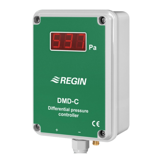
DMD-C
IN20004 REV. B, 2019-10-03
C C a a u u t t i i o o n n ! ! Read and understand the instruction before using the product.
C C a a u u t t i i o o n n ! ! Ensure that the installation complies with local safety
regulations.
C C a a u u t t i i o o n n ! ! Before installation or maintenance, the power supply should first
be disconnected. Installation or maintenance of this unit should only be
carried out by qualified personnel. The manufacturer is not responsible
for any eventual damage or injury caused by inadequate skills during instal-
lation, or through removal of or deactivation of any security devices.
Technical Data
Supply voltage
24 V AC/DC (21...27 V AC/DC)
Power consumption
5 VA
Load impedance, 0...10 V
> 2 kΩ
Load impedance, 4...20 mA
< 500 Ω
Protection class
IP54
Ambient humidity
Max. 90 % RH (non-condensing)
Ambient temperature
0...50 °C
Storage temperature
-40...+50 °C
Media temperature
0...70 °C
Max. overload pressure
20 kPa
Mounting
Wall
Media
Air and non-corrosive gases
Measuring range, pressure
0...100 / 0...300 / 0...500 / 0...999 Pa
Output signal, pressure
0...10 V DC / 4...20 mA
Temperature dependency,
± 0.05 %/°C
pressure
Accuracy, pressure
±1 % full scale at 20 °C
Display
Yes
Display type
LED, three digits
Setpoint range
0...999 Pa depending on selected measur-
ing range
Output signal, controller
0...10 V DC
Cable connection
Screw terminals max. 1.5 mm² (AWG 16)
Pressure connection
Connection pipes for 6 mm tube
Electronic damping
0...20 s
Zero-point adjustment
Manual
P-band
0...300 %
I-time
0...999 s
D-factor
0...999
Dimensions, external (WxHxD)
89 x 129 x 58 mm
Weight (incl. packaging)
0.39 kg
Accessories, included
2 pressure outlets (article MTU) and 2 m
plastic tube, 6 mm
Installation
Mount the unit on a steady, non-vibrating surface. It should preferably
be mounted vertically with the pressure connections pointing
downwards. The two screw pockets located in the lower part of the unit
are used when mounting the unit.
The hose with the positive pressure is mounted to the connector marked
+ on the front cover and the hose with the negative pressure is mounted
to the connector marked -.
Wiring
Terminal
Description
1
Supply voltage
2
System neutral
3
Signal neutral
4
Output signal, 0...10 V DC
5
Output signal, 4...20 mA
DMD-C
Terminal
Description
6
Output signal, controller
7-8
Not used
9
Ground
Teminal 1 is connected to + and teminal 2 to - for DC supply.
The ground should be connected since several protection functions are
internally coupled to this terminal.
Settings
The setting of measuring range, setpoint, electronic damping, PID-
settings and zero-point adjustments are made in the menu system, using
three buttons under the front cover (Up, Down, Enter).
Up and Down are used to scroll upwards and downwards between the
possible settings. Enter is used to select the alternative which currently
appears on the display. If the buttons are left unattended for a period of
10 seconds, the unit automatically returns to running mode.
Always start by setting the working range and doing a zero-point
adjustment. The zero-point adjustment should be done before
connecting the pressure hoses.
A zero-point adjustment is done the following way:
1. Press Enter. The display shows -01.
2. Press Up until the display shows -08.
3. Press Enter and the display shows 000.
4. Press Enter again and the new zero-point is stored in the memory.
After that the transmitter automatically returns to running mode.
The settings are changed the following way:
1. Remove the front cover.
2. Press Enter. The display shows -01.
3. Press Up until the display shows the required menu.
4. Press Enter and the display shows the currently set value. The
display alternates between the value and the menu number.
5. To change the value press the Up or Down buttons until the required
value appears.
6. Press Enter again to confirm the setting which is then stored in the
memory. After that the display automatically returns to running
mode and shows the current pressure.
The pressure signals are automatically scaled to the set working range.
1

Verwandte Anleitungen für Regin DMD-C


Inhaltszusammenfassung für Regin DMD-C
- Seite 1 INSTRUCTION Media Air and non-corrosive gases Terminal Description DMD-C Measuring range, pressure 0...100 / 0...300 / 0...500 / 0...999 Pa Output signal, controller Output signal, pressure 0…10 V DC / 4…20 mA Not used Ground Temperature dependency, ± 0.05 %/°C pressure Teminal 1 is connected to + and teminal 2 to - for DC supply.
-
Seite 2: Installation
Contact Inställningar Typ av display LED, tre siffror AB Regin, Box 116, 428 22 Kållered, Sweden Inställning av mätområde, börvärde, elektronisk dämpning, PID- Tel: +46 31 720 02 00, Fax: +46 31 720 02 50 Börvärdesområde 0…999 Pa beroende på valt mätområde inställningar och nollpunktsjusteringar görs i menysystemet, med hjälp... -
Seite 3: Technische Daten
Installation entfernt oder manipuliert wurden, verursacht werden. I-tid = 0 betyder att integreringsfunktionen är avstängd. Montieren Sie den DMD-C auf eine stabile, schwingungsfreie Oberfläche. Das Gerät sollte möglichst senkrecht und mit den Elektronisk dämpning används om trycksignalen upplevs som ostabil. - Seite 4 6. Drücken Sie dann erneut auf Enter, um die Einstellung zu Signal Masse bestätigen, die dann im Speicher gespeichert wird. Danach schaltet Regin Controls Deutschland GmbH, Haynauer Str. 49, 12249 Berlin, das Gerät dann automatisch in den normalen Betriebsmodus zurück Ausgangssignal 0...10 V DC Deutschland und der aktuelle Druck wird angezeigt.
- Seite 5 6. Appuyer sur Entrée à nouveau pour confirmer l'enregistrement de Neutre (système) la valeur. Ensuite, l'écran revient automatiquement au mode de AB Regin, Box 116, 428 22 Kållered, Sweden Neutre (signal) fonctionnement et affiche la pression actuelle. Tel: +46 31 720 02 00, Fax: +46 31 720 02 50 Signal de sortie, 0...10 V DC...