Inhaltsverzeichnis
Werbung
Quicklinks
Copyright Notice:
No part of this installation guide may be reproduced, transcribed, transmitted, or trans-
lated in any language, in any form or by any means, except duplication of documentation
by the purchaser for backup purpose, without written consent of ASRock Inc.
Products and corporate names appearing in this guide may or may not be registered
trademarks or copyrights of their respective companies, and are used only for identifi ca-
tion or explanation and to the owners' benefi t, without intent to infringe.
Disclaimer:
Specifi cations and information contained in this guide are furnished for informational use
only and subject to change without notice, and should not be constructed as a commit-
ment by ASRock. ASRock assumes no responsibility for any errors or omissions that may
appear in this guide.
With respect to the contents of this guide, ASRock does not provide warranty of any kind,
either expressed or implied, including but not limited to the implied warranties or condi-
tions of merchantability or fi tness for a particular purpose. In no event shall ASRock, its
directors, offi cers, employees, or agents be liable for any indirect, special, incidental, or
consequential damages (including damages for loss of profi ts, loss of business, loss of
data, interruption of business and the like), even if ASRock has been advised of the pos-
sibility of such damages arising from any defect or error in the guide or product.
This device complies with Part 15 of the FCC Rules. Operation is subject to the following
two conditions:
(1) this device may not cause harmful interference, and
(2) this device must accept any interference received, including interference that
may cause undesired operation.
CALIFORNIA, USA ONLY
The Lithium battery adopted on this motherboard contains Perchlorate, a toxic substance
controlled in Perchlorate Best Management Practices (BMP) regulations passed by the
California Legislature. When you discard the Lithium battery in California, USA, please
follow the related regulations in advance.
"Perchlorate Material-special handling may apply, see
www.dtsc.ca.gov/hazardouswaste/perchlorate"
The terms HDMI™ and HDMI High-Defi nition Multimedia Interface, and the HDMI logo
are trademarks or registered trademarks of HDMI Licensing LLC in the United States and
other countries.
1
Werbung
Inhaltsverzeichnis

Verwandte Anleitungen für ASROCK Z68 Extreme7 Gen3


Inhaltszusammenfassung für ASROCK Z68 Extreme7 Gen3
- Seite 1 ASRock. ASRock assumes no responsibility for any errors or omissions that may appear in this guide. With respect to the contents of this guide, ASRock does not provide warranty of any kind, either expressed or implied, including but not limited to the implied warranties or condi- tions of merchantability or fi...
-
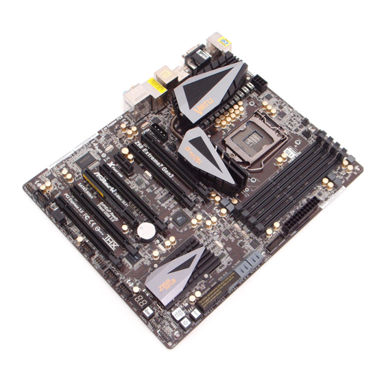
Seite 2: Motherboard-Layout
PCI Express 3.0 x16 Slot (PCIE2, Black) Chassis Speaker Header (SPEAKER 1, Black) 44 PCI Express 2.0 x16 Slot (PCIE1, Black) Clear CMOS Switch (CLRCBTN) SLI / XFIRE Power Connector Dr. Debug Chassis Fan Connector (CHA_FAN3) ASRock Z68 Extreme7 Gen3 Motherboard... - Seite 3 See the table below for connection details in accordance with the type of speaker you use. TABLE for Audio Output Connection Audio Output Channels Front Speaker Rear Speaker Central / Bass Line In or (No. 10) (No. 7) (No. 6) Side Speaker (No. 9) ASRock Z68 Extreme7 Gen3 Motherboard...
- Seite 4 PS/2 Mouse/Keyboard + USB 2.0 Bracket PS/2 Mouse/Keyboard + USB 2.0 Bracket can support one PS2 Mouse/Keyboard port and two additional USB 2.0 ports besides the I/O panel. Please refer to page 43 for proper installation. ASRock Z68 Extreme7 Gen3 Motherboard...
-
Seite 5: Package Contents
In case any modifi cations of this manual occur, the updated version will be available on ASRock website without further notice. You may fi nd the latest VGA cards and CPU support lists on ASRock website as well. - Seite 6 Sandy Bridge CPU - Max. shared memory 1759MB (see CAUTION 6) - Four VGA Output options: D-Sub, DVI-D, HDMI and DisplayPort (see CAUTION 7) - Supports HDMI 1.4a Technology with max. resolution up to 1920x1200 @ 60Hz ASRock Z68 Extreme7 Gen3 Motherboard...
- Seite 7 SATA3 - 2 x SATA3 6.0 Gb/s connectors by Intel Z68, support RAID (RAID 0, RAID 1, RAID 10, RAID 5, Intel Rapid Storage and Intel Smart Response Technology), NCQ, AHCI and “Hot Plug” functions ASRock Z68 Extreme7 Gen3 Motherboard...
-
Seite 8: Smart Switch
- CPU Core, IGPU, DRAM, PCH, CPU PLL, VTT, VCCSA Voltage Multi-adjustment Support CD - Drivers, Utilities, AntiVirus Software (Trial Version), CyberLink MediaEspresso 6.5 Trial, ASRock Software Suite (CyberLink DVD Suite - OEM and Trial; ASRock MAGIX Multimedia Suite - OEM) ASRock Z68 Extreme7 Gen3 Motherboard... - Seite 9 - FCC, CE, WHQL - ErP/EuP Ready (ErP/EuP ready power supply is required) (see CAUTION 22) * For detailed product information, please visit our website: http://www.asrock.com WARNING Please realize that there is a certain risk involved with overclocking, including adjusting the setting in the BIOS, applying Untied Overclocking Technology, or using the third-party overclocking tools.
- Seite 10 6-channel, and 8-channel modes. Please check the table on page 3 for proper connection. 10. ASRock Extreme Tuning Utility (AXTU) is an all-in-one tool to fi ne-tune different system functions in a user-friendly interface, which is including Hardware Monitor, Fan Control, Overclocking, OC DNA and IES. In Hardware Monitor, it shows the major readings of your system.
- Seite 11 11. ASRock Instant Flash is a BIOS fl ash utility embedded in Flash ROM. This convenient BIOS update tool allows you to update system BIOS ® without entering operating systems fi rst like MS-DOS or Windows . With this utility, you can press <F6> key during the POST or press <F2> key to BIOS setup menu to access ASRock Instant Flash.
- Seite 12 GPU and advanced media features of Intel graphics. 18. ASRock On/Off Play Technology allows users to enjoy the great audio ex- perience from the portable audio devices, such like MP3 player or mobile phone to your PC, even when the PC is turned off (or in ACPI S5 mode)! This motherboard also provides a free 3.5mm audio cable (optional) that...
-
Seite 13: Cpu Installation
CPU surface is unclean or if there is any bent pin on the socket. Do not force to insert the CPU into the socket if above situation is found. Other- wise, the CPU will be seriously damaged. ASRock Z68 Extreme7 Gen3 Motherboard... - Seite 14 Pin1 Pin1 alignment key 1155-Pin Socket orientation key notch 1155-Pin CPU For proper inserting, please ensure to match the two orientation key notches of the CPU with the two alignment keys of the socket. ASRock Z68 Extreme7 Gen3 Motherboard...
- Seite 15 Please be noticed that this motherboard supports Combo Cooler Option (C.C.O.), which provides the fl exible option to adopt three dif- ferent CPU cooler types, Socket LGA 775, LGA 1155 and LGA 1156. The white throughholes are for Socket LGA 1155/1156 CPU fan. ASRock Z68 Extreme7 Gen3 Motherboard...
- Seite 16 DDR3 slot; otherwise, this motherboard and DIMM may be dam- aged. Some DDR3 1GB double-sided DIMMs with 16 chips may not work on this motherboard. It is not recommended to install them on this motherboard. ASRock Z68 Extreme7 Gen3 Motherboard...
-
Seite 17: Installing A Dimm
DIMM if you force the DIMM into the slot at incorrect orientation. Step 3. Firmly insert the DIMM into the slot until the retaining clips at both ends fully snap back in place and the DIMM is properly seated. ASRock Z68 Extreme7 Gen3 Motherboard... -
Seite 18: Installing An Expansion Card
Step 2. Remove the system unit cover (if your motherboard is already installed in a chassis). Step 3. Remove the bracket facing the slot that you intend to use. Keep the screws for later use. ASRock Z68 Extreme7 Gen3 Motherboard... - Seite 19 Align the card connector with the slot and press fi rmly until the card is completely seated on the slot. Step 5. Fasten the card to the chassis with screws. Step 6. Replace the system cover. ASRock Z68 Extreme7 Gen3 Motherboard...
- Seite 20 PCIE1 slot and the other graphics card to PCIE4 slot. Make sure that the cards are properly seated on the slots. Step2. If required, connect the auxiliary power source to the PCI Express graph- ics cards. ASRock Z68 Extreme7 Gen3 Motherboard...
- Seite 21 Step3. Align and insert ASRock SLI_Bridge_2S Card to the goldfi ngers on each graphics card. Make sure ASRock SLI_Bridge_2S Card is fi rmly in place. ASRock SLI_Bridge_2S Card Step4. Connect a VGA cable or a DVI cable to the monitor connector or the DVI connector of the graphics card that is inserted to PCIE1 slot.
- Seite 22 Repeat this step on the three graphics cards. Step3. Align and insert ASRock 3-Way SLI-2S2S Bridge Card to the goldfi ngers on each graphics card. Make sure ASRock 3-Way SLI-2S2S Bridge Card is fi rmly in place.
- Seite 23 Set PhysX GPU acceleration item, please select Enabled. In Select an SLI confi guration item, please select Enable SLI. And click Apply. C. Reboot your system. D. You can freely enjoy the benefi t of SLI feature. ASRock Z68 Extreme7 Gen3 Motherboard...
-
Seite 24: For Windows
Set PhysX GPU acceleration item, please select Enabled. In Select an SLI confi guration item, please select Enable SLI. And click Apply. F. Reboot your system. G. You can freely enjoy the benefi t of SLI or Quad SLI feature. ASRock Z68 Extreme7 Gen3 Motherboard... - Seite 25 D. You can freely enjoy the benefi t of 3-Way SLI feature. ® * SLI appearing here is a registered trademark of NVIDIA Technologies Inc., and is used only for identifi cation or explanation and to the owners’ benefi t, without intent to infringe. ASRock Z68 Extreme7 Gen3 Motherboard...
- Seite 26 AMD graphics card manuals for detailed installation guide. Step 1. Insert one Radeon graphics card into PCIE1 slot and the other Radeon graphics card to PCIE4 slot. Make sure that the cards are properly seated on the slots. ASRock Z68 Extreme7 Gen3 Motherboard...
- Seite 27 Connect the DVI monitor cable to the DVI connector on the Radeon graphics card on PCIE1 slot. (You may use the DVI to D-Sub adapter to convert the DVI connector to D-Sub interface, and then connect the D-Sub monitor cable to the DVI to D-Sub adapter.) ASRock Z68 Extreme7 Gen3 Motherboard...
- Seite 28 Bridge to connect Radeon graphics cards on PCIE4 and PCIE6 slots. (CrossFire Bridge is provided with the graphics card you purchase, not bundled with this motherboard. Please refer to your graphics card vendor for details.) ASRock Z68 Extreme7 Gen3 Motherboard...
- Seite 29 Connect the DVI monitor cable to the DVI connector on the Radeon graph- ics card on PCIE1 slot. (You may use the DVI to D-Sub adapter to convert the DVI connector to D-Sub interface, and then connect the D-Sub monitor cable to the DVI to D-Sub adapter.) ASRock Z68 Extreme7 Gen3 Motherboard...
- Seite 30 ”, and then check the item “Enable CrossFireX ”. Select “2 GPUs” and click “Apply” (if you install two Radeon graphics cards). Select “3 GPUs” and click “OK” (if you install three Radeon graphics cards). ASRock Z68 Extreme7 Gen3 Motherboard...
- Seite 31 AMD Technologies Inc., and is used only for identifi cation or explanation and to the owners’ benefi t, without intent to infringe. * For further information of AMD CrossFireX technology, please check AMD website for updates and details. ASRock Z68 Extreme7 Gen3 Motherboard...
- Seite 32 If you haven’t installed onboard VGA driver yet, please install onboard VGA driver from our support CD to your system and restart your computer. D-Sub, DVI-D, HDMI and DisplayPort monitors cannot be enabled at the same time. You can only choose two of them. ASRock Z68 Extreme7 Gen3 Motherboard...
- Seite 33 D. Click “Extend my Windows desktop onto this monitor”. E. Right-click the display icon and select “Attached”, if necessary. F. Set the “Screen Resolution” and “Color Quality” as appropriate for the second monitor. Click “Apply” or “OK” to apply these new values. ASRock Z68 Extreme7 Gen3 Motherboard...
- Seite 34 PCs requires a secure connection to a compliant display. Due to the increase in manufacturers employing HDCP in their equipment, it is highly recommended that the HDTV or LCD monitor you purchase is compatible. ASRock Z68 Extreme7 Gen3 Motherboard...
- Seite 35 Hot-Plug function. Please install it before you boot the system. * ASRock Smart Remote is only supported by some of ASRock motherboards. Please refer to ASRock website for the motherboard support list: http://www.asrock.com ASRock Z68 Extreme7 Gen3 Motherboard...
- Seite 36 No. 4 2. USB 2.0 port (USB6) header see p.2 No. 27 With ASRock XFast Charger feature, you can freely enjoy the quick charging convenience by installing the USB cable on these two ports. ASRock Z68 Extreme7 Gen3 Motherboard...
- Seite 37 Please be noted that the password, date, time, user default profi le, 1394 GUID and MAC address will be cleared only if the CMOS battery is removed. The Clear CMOS Switch has the same function as the Clear CMOS jumper. ASRock Z68 Extreme7 Gen3 Motherboard...
- Seite 38 (Optional) connect to the SATA Then connect the white end of HDD power connector SATA power cable to the power connect to the power supply connector of the power supply. ASRock Z68 Extreme7 Gen3 Motherboard...
- Seite 39 (19-pin USB3_5_6) IntA_P2_SSTX+ IntA_P2_SSTX- one USB 3.0 header on this (see p.2 No. 9) IntA_P2_SSRX+ IntA_P2_SSRX- motherboard. This USB 3.0 Vbus header can support two USB 3.0 ports. Vbus IntA_P1_SSRX- IntA_P1_SSRX+ IntA_P1_SSTX- IntA_P1_SSTX+ IntA_P1_D- IntA_P1_D+ ASRock Z68 Extreme7 Gen3 Motherboard...
- Seite 40 PWRBTN (Power Switch): Connect to the power switch on the chassis front panel. You may confi gure the way to turn off your system using the power switch. ASRock Z68 Extreme7 Gen3 Motherboard...
- Seite 41 (4-pin CHA_FAN1) +12V FAN_SPEED_CONTROL match the black wire to the (see p.2 No. 31) ground pin. (3-pin CHA_FAN2) (see p.2 No. 30) (3-pin CHA_FAN3) (see p.2 No. 46) (3-pin PWR_FAN1) (see p.2 No. 3) ASRock Z68 Extreme7 Gen3 Motherboard...
-
Seite 42: Atx Power Connector
SLI/XFIRE Power Connector It is not necessary to use this connector, but please connect it (4-pin SLI/XFIRE_PWR1) with a hard disk power (see p.2 No. 45) SLI/XFIRE_POWER1 connecor when two graphics cards are plugged to this motherboard. ASRock Z68 Extreme7 Gen3 Motherboard... - Seite 43 PS2 header, and connect the 9-pin connector on the bracket cable to the USB 2.0 header (USB2_3, USB4_5, USB6_7 or USB8_9) and fasten the bracket to the chassis with screws. ASRock Z68 Extreme7 Gen3 Motherboard...
- Seite 44 Put the USB 3.0 cable and the rear Panel. USB 3.0 bracket together. Step 3 Step 4 Screw the two screws into the rear USB 3.0 Put the rear USB 3.0 bracket into the bracket. chassis. ASRock Z68 Extreme7 Gen3 Motherboard...
-
Seite 45: Smart Switches
(RSTBTN) RESET the system. (see p.2 No. 16) Clear CMOS Switch Clear CMOS Switch is a smart switch, allowing users to quickly (CLRCBTN) CMOS clear the CMOS values. (see p.2 No. 23) ASRock Z68 Extreme7 Gen3 Motherboard... - Seite 46 CPU post-memory initialization is started 0x33 CPU post-memory initialization. Cache initialization 0x34 CPU post-memory initialization. Application Processor(s) (AP) initialization 0x35 CPU post-memory initialization. Boot Strap Processor (BSP) selection 0x36 CPU post-memory initialization. System Management Mode (SMM) initialization ASRock Z68 Extreme7 Gen3 Motherboard...
- Seite 47 Reserved for future AMI progress codes 0xF8 Recovery PPI is not available 0xF9 Recovery capsule is not found 0xFA Invalid recovery capsule 0xFB – 0xFF Reserved for future AMI error codes 0x60 DXE Core is started 0x61 NVRAM initialization ASRock Z68 Extreme7 Gen3 Motherboard...
- Seite 48 USB Detect 0x9D USB Enable 0x9E – 0x9F Reserved for future AMI codes 0xA0 IDE initialization is started 0xA1 IDE Reset 0xA2 IDE Detect 0xA3 IDE Enable 0xA4 SCSI initialization is started 0xA5 SCSI Reset ASRock Z68 Extreme7 Gen3 Motherboard...
- Seite 49 No Console Input Devices are found 0xD8 Invalid password 0xD9 Error loading Boot Option (LoadImage returned error) 0xDA Boot Option is failed (StartImage returned error) 0xDB Flash update is failed 0xDC Reset protocol is not available ASRock Z68 Extreme7 Gen3 Motherboard...
-
Seite 50: Installing Windows
B. Set the option “SATA Mode” to [IDE] for SATA2_2 to SATA2_5 and SATA3_0 and SATA3_1 ports. Set the option “ASMedia SATA3 Mode” to [IDE] for SATA3_A1 to SATA3_A4 ports.) ® STEP 2: Install Windows XP / XP 64-bit OS on your system. ASRock Z68 Extreme7 Gen3 Motherboard... - Seite 51 B. Set the option “SATA Mode” to [AHCI] for SATA2_2 to SATA2_5 and SATA3_0 and SATA3_1 ports. Set the option “ASMedia SATA3 Mode” to [AHCI] for SATA3_A1 to SATA3_A4 ports.) ® STEP 2: Install Windows 7 / 7 64-bit / Vista / Vista 64-bit OS on your system. ASRock Z68 Extreme7 Gen3 Motherboard...
- Seite 52 “Unassigned Adapters” sections, which means all adapters are already assigned to teams. 3. Click Expert Mode. * If you want to always use Expert Mode to create a team, click Default to Expert Mode on next start. ASRock Z68 Extreme7 Gen3 Motherboard...
- Seite 53 * Adding a network adapter to a team where its driver is disabled may negatively affect the offl oading capabilities of the team. This may have an impact on the team’s performance. Therefore, it is recommended that only driver-enabled network adapters be added as members to a team. ASRock Z68 Extreme7 Gen3 Motherboard...
- Seite 54 * When confi guring an SLB team, although connecting team members to a hub is supported for testing, it is recommended to connect team members to a switch. * Not all network adapters made by others are supported or fully certifi ed for teaming. ASRock Z68 Extreme7 Gen3 Motherboard...
- Seite 55 On the General tab, click Internet Protocol (TCP/IP), and then click Properties. d. Confi gure the IP address and any other necessary TCP/IP confi guration for the team, and then click OK when fi nished. ASRock Z68 Extreme7 Gen3 Motherboard...
- Seite 56 It will display the Main Menu automatically if “AUTORUN” is enabled in your computer. If the Main Menu does not appear automatically, locate and double-click on the fi le “ASSETUP.EXE” from the BIN folder in the Support CD to display the menus. ASRock Z68 Extreme7 Gen3 Motherboard...
-
Seite 57: Einführung
1. Einführung Wir danken Ihnen für den Kauf des ASRock Z68 Extreme7 Gen3 Motherboard, ein zuverlässiges Produkt, welches unter den ständigen, strengen Qualitätskontrollen von ASRock gefertigt wurde. Es bietet Ihnen exzellente Leistung und robustes De- sign, gemäß der Verpfl ichtung von ASRock zu Qualität und Halbarkeit. Diese Sch- nellinstallationsanleitung führt in das Motherboard und die schrittweise Installation... -
Seite 58: Spezifikationen
HD Graphics 2000/3000, Intel Advanced Vector Extensions (AVX) ® - Pixel Shader 4.1, DirectX 11 mit Intel Ivy Bridge-Prozessor, ® DirectX 10.1 mit Intel Sandy Bridge-Prozessor - Maximal gemeinsam genutzter Speicher 1759MB (siehe VORSICHT 6) ASRock Z68 Extreme7 Gen3 Motherboard... -
Seite 59: E/A-Anschlüsse An Der Rückseite
- 2 x RJ-45 LAN Port mit LED (ACT/LINK LED und SPEED LED) - 1 x IEEE 1394 Port - HD Audiobuchse: Lautsprecher hinten / Mitte/Bass / Audioeingang / Lautsprecher vorne / Mikrofon (siehe VORSICHT 9) ASRock Z68 Extreme7 Gen3 Motherboard... -
Seite 60: Anschlüsse
- 1 x CMOS löschen-Schalter mit LED - 1 x Netzschalter mit LED - 1 x Rücksetzschalter (Reset) mit LED BIOS - 64Mb AMI BIOS - AMIs Legal BIOS UEFI mit GUI-Unterstützung - Unterstützung für “Plug and Play” - ACPI 1.1-Weckfunktionen ASRock Z68 Extreme7 Gen3 Motherboard... - Seite 61 - CPU Core, IGPU, DRAM, PCH, CPU PLL, VTT, VCCSA Stromspannung Multianpassung CD d’assistance - Pilotes, utilitaires, logiciel anti-virus (version d’évaluation), CyberLink MediaEspresso 6.5 Trial, Suite logicielle ASRock (CyberLink DVD Suite et Version OEM et d’essai; ASRock MAGIX-Multimedia-Suite - OEM) Einzigartige - ASRock Extreme Tuning Utility (AXTU) Eigenschaft...
- Seite 62 7 64-Bit / 7 unter- stützt. Der Deep Color-Modus wird nur aktiviert, wenn der Bildschirm ® 12bpc in EDID unterstützt. HBR wird unter Windows 7 64 Bit / 7 / Vista 64 Bit / Vista unterstützt. ASRock Z68 Extreme7 Gen3 Motherboard...
- Seite 63 APP Charger. Installieren Sie einfach den ASRock APP Charger-Treiber; dadurch lädt sich Ihr iPhone wesentlich schneller über einen Computer auf – genaugenommen bis zu 40 % schneller als zuvor. Der ASRock APP Charger ermöglicht Ihnen die schnelle Aufl adung mehrerer Apple-Geräte gleichzeitig;...
- Seite 64 14. ASRocks XFast USB dient der Steigerung der Leistungsfähigkeit Ihrer USB-Speichergeräte. Die Leistung kann je nach Eigenschaften des Gerätes variieren. 15. ASRock XFast LAN bietet einen schnelleren Internetzugang mit den nachfolgenden Vorteilen. LAN-Anwendungspriorisierung: Hiermit kon- fi gurieren Sie auf ideale Weise Ihre Anwendungspriorität und/oder fügen neue Programme hinzu.
- Seite 65 Empfehlung von Intel muss eine EuP-fähige Stromversorgung dem Standard entsprechen, was bedeutet, dass bei einem Stromverbrauch von 100 mA die 5-Volt-Standby-Energieeffi zienz höher als 50% sein sollte. Für die Wahl einer EuP-fähigen Stromversorgung empfehlen wir Ihnen, weitere Details beim Hersteller der Stromversorgung abzufragen. ASRock Z68 Extreme7 Gen3 Motherboard...
-
Seite 66: Einstellung Der Jumper
1.4 Integrierte Header und Anschlüsse Integrierte Header und Anschlüsse sind KEINE Jumper. Setzen Sie KE- INE Jumperkappen auf diese Header und Anschlüsse. Wenn Sie Jump- erkappen auf Header und Anschlüsse setzen, wird das Motherboard unreparierbar beschädigt! ASRock Z68 Extreme7 Gen3 Motherboard... - Seite 67 Serial ATA- (SATA-) Verbinden Sie das schwarze Stromversorgungskabel Ende des SATA-Netzkabels mit dem Netzanschluss am (Option) Verbindung zum Laufwerk. Verbinden Sie dann SATA-HDD-Stromanschluss das weiße Ende des SATA- Verbindung zum Netzteil Stromversorgungskabels mit dem Stromanschluss des Netzteils. ASRock Z68 Extreme7 Gen3 Motherboard...
- Seite 68 USB 3.0- (siehe S.2 - No. 9) IntA_P2_SSRX+ IntA_P2_SSRX- Header an diesem Vbus Motherboard. Dieser USB 3.0- Header kann zwei USB 3.0- Ports unterstützen. Vbus IntA_P1_SSRX- IntA_P1_SSRX+ IntA_P1_SSTX- IntA_P1_SSTX+ IntA_P1_D- IntA_P1_D+ ASRock Z68 Extreme7 Gen3 Motherboard...
- Seite 69 / Vista 64 Bit: Wählen Sie im Realtek-Bedienfeld die „FrontMic“ (Vorderes Mikrofon)- Registerkarte. Passen Sie die „Recording Volume“ (Aufnahmelautstärke) System Panel-Header Dieser Header unterstützt mehrere Funktion der (9-pin PANEL1) Systemvorderseite. (siehe S.2 - No. 21) ASRock Z68 Extreme7 Gen3 Motherboard...
-
Seite 70: Gehäuselautsprecher-Header
(siehe S.2 - No. 20) PLED+ PLED+ Systembetriebsstatus an diesem Header an. Die LED leuchtet, wenn das System in Betrieb ist. Die LED blinkt im S1-Zustand. Im S3-/S4- oder S5-Zustand (ausgeschaltet) leuchtet die LED nicht. ASRock Z68 Extreme7 Gen3 Motherboard... - Seite 71 Stromanschluss bietet, kann es auch mit einem modifi zierten traditionellen 20-pol. ATX-Netzteil verwendet werden. Um ein 20-pol. ATX-Netzteil zu verwenden, stecken Sie den Stecker mit Pin 1 und Pin 13 ein. Installation eines 20-pol. ATX-Netzteils ASRock Z68 Extreme7 Gen3 Motherboard...
-
Seite 72: Com-Anschluss-Header
IEEE-1394 Header +12V (FRONT_1394) auf dieser RXTPBP_0 Hauptplatine. Dieser IEEE-1394 RXTPAP_0 Header kann einen IEEE-1394 Port unterstützen. COM-Anschluss-Header Dieser COM-Anschluss- Header wird verwendet, um (9-pin COM1) ein COM-Anschlussmodul zu (siehe S.2 - No. 35) unterstützen. ASRock Z68 Extreme7 Gen3 Motherboard... - Seite 73 5-poligen Stecker des Kabels Ihres Anschlussblechs mit der PS/2-Stiftleiste; verbinden Sie den 9-poligen Stecker des Kabels Ihres Anschlussblechs mit der USB 2.0-Stiftleiste (USB2_3, USB4_5, USB6_7 oder USB8_9) und befestigen das Blech mit Schrauben am Gehäuse. ASRock Z68 Extreme7 Gen3 Motherboard...
- Seite 74 Installieren Sie die USB 3.0-Frontblende im mit sechs Gehäuseschrauben am 2,5 Zoll-Festplatteneinschub des Gehäuses. Festplatteneinschub. Schritt 5 Schritt 6 Schließen Sie das Kabel der Die USB 3.0-Frontblende ist nun USB 3.0-Frontblende am USB 3.0-Header einsatzbereit. (USB3_5_6) am Motherboard an. ASRock Z68 Extreme7 Gen3 Motherboard...
- Seite 75 RESET Benutzer das System schnell (siehe S.2 - No. 16) zurücksetzen können. CMOS löschen-Schalter Der CMOS löschen-Schalter ist ein Schnellschalter, mit dem (CLRCBTN) CMOS Benutzer die CMOS-Werte (siehe S.2 - No. 23) schnell löschen können. ASRock Z68 Extreme7 Gen3 Motherboard...
- Seite 76 ASSETUP.EXE im BIN-Verzeichnis der Support-CD, um die Menüs aufzurufen. Das Setup-Programm soll es Ihnen so leicht wie möglich machen. Es ist menüges- teuert, d.h. Sie können in den verschiedenen Untermenüs Ihre Auswahl treffen und die Programme werden dann automatisch installiert. ASRock Z68 Extreme7 Gen3 Motherboard...
-
Seite 77: Contenu Du Paquet
1. Introduction Merci pour votre achat d’une carte mère ASRock Z68 Extreme7 Gen3, une carte mère très fiable produite selon les critères de qualité rigoureux de ASRock. Elle offre des performances excellentes et une conception robuste conformément à l’engagement d’ASRock sur la qualité et la fi abilité au long terme. - Seite 78 VGA sur carte - Supporte Intel HD Graphics Built-in Visuals: Intel Quick ® ® Sync Video, Intel InTru 3D, Intel Clear Video HD ® ® Technology, Intel HD Graphics 2000/3000, Intel Advanced Vector Extensions (AVX) ASRock Z68 Extreme7 Gen3 Motherboard...
-
Seite 79: Panneau Arrière
- 1 x port DVI-D - 1 x port HDMI - 1 x DisplayPort - 1 x Port de sortie optique SPDIF - 2 x ports USB 2.0 par défaut - 1 x Connecteur eSATA3 ASRock Z68 Extreme7 Gen3 Motherboard... - Seite 80 - Connecteur d’alimentation SLI/XFIRE - Connecteur audio panneau avant - 4 x En-tête USB 2.0 (prendre en charge 8 ports USB 2.0 supplémentaires) - 1 x En-tête USB 3.0 (prendre en charge 2 ports USB 3.0 supplémentaires) ASRock Z68 Extreme7 Gen3 Motherboard...
- Seite 81 - CPU Core, IGPU, DRAM, PCH, CPU PLL, VTT, VCCSA Tension Multi-ajustement CD d’assistance - Pilotes, utilitaires, logiciel anti-virus (version d’évaluation), CyberLink MediaEspresso 6.5 Trial, Suite logicielle ASRock (CyberLink DVD Suite et Version OEM et d’essai; Suite multimédia ASRock MAGIX - OEM) Caractéristique...
- Seite 82 à la page 18. La dimension maximum du memoire partage est defi nie par le vendeur ® de jeu de puces et est sujet de changer. Veuillez verifi er la Intel website pour les informations recentes SVP. ASRock Z68 Extreme7 Gen3 Motherboard...
- Seite 83 ASRock Extreme Tuning Utility (AXTU). Site Web de ASRock : http://www.asrock.com 11. O ASRock Instant Flash é um utilitário de fl ash do BIOS incorporado na memória Flash ROM. Esta prática ferramenta de actualização do BIOS permite-lhe actualizar o BIOS do sistema sem necessitar de entrar nos ®...
- Seite 84 USB. Les performances réelles dépendent des propriétés du périphérique. 15. ASRock XFast LAN fournit un accès Internet plus rapide, avec les avan- tages suivants. Priorisation d’application LAN : Vous pouvez confi gurer votre priorité d’application idéalement et/ou ajouter des nouveaux pro- grammes.
- Seite 85 électrique de 5v en mode de veille doit être supérieure à 50% pour 100 mA de consommation de courant. Pour choisir une alimentation électrique conforme à la norme EuP, nous vous recommandons de con- sulter votre fournisseur de courant pour plus de détails. ASRock Z68 Extreme7 Gen3 Motherboard...
- Seite 86 Les en-têtes et connecteurs sur carte NE SONT PAS des cavaliers. NE PAS placer les capuchons de cavalier sur ces en-têtes et con- necteurs. Le fait de placer les capuchons de cavalier sur les en-têtes et connecteurs causera à la carte mère des dommages irréversibles! ASRock Z68 Extreme7 Gen3 Motherboard...
- Seite 87 Connectez ensuite l’extrémité c o n n e c t e r à d’alimentation du blanche du cordon l’unité disque d’alimentation d’alimentation SATA sur le dur SATA électrique connecteur d’alimentation de l’unité d’alimentation électrique. ASRock Z68 Extreme7 Gen3 Motherboard...
- Seite 88 E/S, il y a une barrette (voir p.2 No. 9) IntA_P2_SSRX+ USB 3.0 sur la carte mère. IntA_P2_SSRX- Vbus Cette barrette USB 3.0 peut prendre en charge deux ports USB 3.0. Vbus IntA_P1_SSRX- IntA_P1_SSRX+ IntA_P1_SSTX- IntA_P1_SSTX+ IntA_P1_D- IntA_P1_D+ ASRock Z68 Extreme7 Gen3 Motherboard...
- Seite 89 Connectez l’interrupteur d’alimentation, l’interrupteur de réinitialisation et l’indicateur d’état du système du châssis sur cette barrette en respectant l’affectation des broches décrite ci-dessous. Faites attention aux broches positives et négatives avant de connecter les câbles. ASRock Z68 Extreme7 Gen3 Motherboard...
- Seite 90 Connecteur pour châssis et ventilateur Branchez les câbles du ventilateur aux connecteurs pour (CHA_FAN1 br. 4) CHA_FAN_SPEED (voir p.2 No. 31) +12V ventilateur et faites correspondre FAN_SPEED_CONTROL le fi l noir à la broche de terre. ASRock Z68 Extreme7 Gen3 Motherboard...
- Seite 91 à l’alimentation électrique ainsi qu’aux broches 1 et 13. 20-Installation de l’alimentation électrique ATX Connecteur ATX 12V Veuillez connecter une unité d’alimentation électrique ATX (ATX12V1 br.8) 12V sur ce connecteur. (voir p.2 No. 1) ASRock Z68 Extreme7 Gen3 Motherboard...
- Seite 92 (voir p.2 No. 37) et permettant au système de se connecter au un téléviseur numérique HDMI /un projecteur / un périphérique LCD. Veuillez brancher le connecteur HDMI_SPDIF de la carte VGA HDMI sur ce connecteur. ASRock Z68 Extreme7 Gen3 Motherboard...
- Seite 93 Etape 3 Etape 4 Vissez le panneau USB 3.0 frontal dans la Installez le panneau USB 3.0 frontal dans la baie de disque avec les six vis de châssis. baie de disque 2,5” du châssis. ASRock Z68 Extreme7 Gen3 Motherboard...
- Seite 94 (voir p.2 No. 17) à l’utilisateur d’allumer/éteindre rapidement le système. Interrupteur de réinitialisation L’interrupteur de réinitialisation (RSTBTN) est un interrupteur rapide, qui (voir p.2 No. 16) RESET permet à l’utilisateur de réinitialiser rapidement le système. ASRock Z68 Extreme7 Gen3 Motherboard...
- Seite 95 CD-ROM. Le Menu principal s’affi che automatiquement si “AUTORUN” est activé dans votre ordinateur. Si le Menu principal n’apparaît pas automatiquement, locali- sez dans le CD technique le fi chier “ASSETUP.EXE” dans le dossier BIN et double- cliquez dessus pour affi cher les menus. ASRock Z68 Extreme7 Gen3 Motherboard...
-
Seite 96: Contenuto Della Confezione
1. Introduzione Grazie per aver scelto una scheda madre ASRock Z68 Extreme7 Gen3, una sche- da madre affi dabile prodotta secondo i severi criteri di qualità ASRock. Le prestazi- oni eccellenti e il design robusto si conformano all’impegno di ASRock nella ricerca della qualità... - Seite 97 Extensions (AVX) ® - Pixel Shader 4.1, DirectX 11 con CPU Intel Ivy Bridge, ® DirectX 10.1 con CPU Intel Sandy Bridge - Pixel Shader 4.1, DirectX 10.1 - Memoria massima condivisa 1759MB (vedi ATTENZIONE 6) ASRock Z68 Extreme7 Gen3 Motherboard...
- Seite 98 - 2 x porte LAN RJ-45 con LED (LED azione/collegamento e LED velocità) - 1 x porte IEEE 1394 - Connettore HD Audio: cassa posteriore / cassa centrale / bassi / ingresso linea / cassa frontale / microfono (vedi ATTENZIONE 9) ASRock Z68 Extreme7 Gen3 Motherboard...
- Seite 99 - AMI UEFI Legal BIOS con interfaccia di supporto - Supporta “Plug and Play” - Compatibile con ACPI 1.1 wake up events - Supporta jumperfree - Supporta SMBIOS 2.3.1 - Regolazione multi-voltaggio CPU Core, IGPU, DRAM, PCH, CPU PLL, VTT, VCCSA ASRock Z68 Extreme7 Gen3 Motherboard...
- Seite 100 SO XP 64 bit Certifi cazioni - FCC, CE, WHQL - Predisposto ErP/EuP (è necessaria l’alimentazione predisposta per il sistema ErP/EuP) (vedi ATTENZIONE 22) * Per ulteriori informazioni, prego visitare il nostro sito internet: http://www.asrock.com ASRock Z68 Extreme7 Gen3 Motherboard...
- Seite 101 Questa scheda madre supporta l’ingresso stereo e mono per il microfono. Questa scheda madre supporta le modalità 2 canali, 4 canali, 6 canali e 8 canali per l’uscita audio. Controllare la tavola a pagina 3 per eseguire il collegamento appropriato. ASRock Z68 Extreme7 Gen3 Motherboard...
- Seite 102 AXTU (ASRock Extreme Tuning Utility). Sito ASRock: http://www.asrock.com 11. ASRock Instant Flash è una utilità Flash BIOS integrata nella Flash ROM. Questo comodo strumento d’aggiornamento del BIOS permette di aggior- nare il sistema BIOS senza accedere a sistemi operativi come MS-DOS ®...
- Seite 103 USB. Le prestazioni dipendono dalle proprietà del dispositivo. 15. ASRock XFast LAN offre un accesso a Internet più veloce, che compren- de i seguenti benefi ci. Priorità alle applicazioni LAN: è possibile confi gu- rare la priorità assegnata alle applicazioni in modo ideale e/o aggiungere nuovi programmi.
- Seite 104 I collettori ed i connettori su scheda NON sono dei jumper. NON instal- lare cappucci per jumper su questi collettori e connettori. L’installazione di cappucci per jumper su questi collettori e connettori provocherà danni permanenti alla scheda madre! ASRock Z68 Extreme7 Gen3 Motherboard...
- Seite 105 SATA al connettore di alimentazione del (Opzionale) Connettere all’ailmentazio- drive. Poi connettete l’estremità Connettere al grup- dei dischi SATA bianca del cavo di alimentazio ne SATA al connettore power di alimentazione dell’alimentatore. ASRock Z68 Extreme7 Gen3 Motherboard...
- Seite 106 I/O, (19-pin USB3_5_6) IntA_P2_SSTX+ IntA_P2_SSTX- questa scheda madre è dotata (vedi p.2 Nr. 9) IntA_P2_SSRX+ IntA_P2_SSRX- di un header USB 3.0 che Vbus supporta due porte USB 3.0. Vbus IntA_P1_SSRX- IntA_P1_SSRX+ IntA_P1_SSTX- IntA_P1_SSTX+ IntA_P1_D- IntA_P1_D+ ASRock Z68 Extreme7 Gen3 Motherboard...
- Seite 107 Andare alla scheda “FrontMic” (Microfono frontale) del pannello di controllo Realtek. Regolare la voce “Recording Volume” (Volume registrazione). Collettore pannello di sistema Questo collettore accomoda diverse funzioni di sistema (9-pin PANEL1) pannello frontale. (vedi p.2 Nr. 21) ASRock Z68 Extreme7 Gen3 Motherboard...
- Seite 108 Il (vedi p.2 Nr. 20) PLED+ PLED+ LED è acceso quando il sistema è in funzione. Il LED continua a lampeggiare in stato S1. Il LED è spento in stato S3/S4 o S5 (spegnimento). ASRock Z68 Extreme7 Gen3 Motherboard...
- Seite 109 ATX a 24 pin, ma può funzionare lo stesso se si adotta un alimentatore ATX a 20 pin. Per usare l’alimentatore ATX a 20 pin, collegare l’alimentatore con il Pin 1 e il Pin 13. Installazione dell’alimentatore ATX a 20 pin ASRock Z68 Extreme7 Gen3 Motherboard...
- Seite 110 SPDIF su scheda (2-pin HDMI_SPDIF1) SPDIFOUT HDMI VGA, consente al (vedi p.2 Nr. 37) sistema di collegare dispositivi per TV digitale HDMI/proiettori/ LCD . Collegare il connettore HDMI_SPDIF della scheda VGA HDMI a questo header. ASRock Z68 Extreme7 Gen3 Motherboard...
- Seite 111 5 pin sul cavo della staffa all’header PS2, quindi collegare il connettore a 9 pin sul cavo della staffa all’header USB 2.0 (USB2_3, USB4_5, USB6_7 o USB8_9) e fi ssare la staffa allo chassis con le apposite viti. ASRock Z68 Extreme7 Gen3 Motherboard...
- Seite 112 Punto 2 Collegare il cavo USB 3.0 e il anteriore. supporto USB 3.0 posteriore. Punto 3 Punto 4 Avvitare le due viti nel supporto USB 3.0 Inserire il supporto USB 3.0 posteriore. posteriore nel telaio. ASRock Z68 Extreme7 Gen3 Motherboard...
- Seite 113 (vedi p.2 Nr. 16) agli utenti di resettare rapidamente il sistema. Interruttore pulizia CMOS L’interruttore di pulizia CMOS è (CLRCBTN) un interruttore rapido che (vedi p.2 Nr. 23) CMOS consente agli utenti di cancellare velocemente i valori CMOS. ASRock Z68 Extreme7 Gen3 Motherboard...
- Seite 114 Inserire il CD di supporto nel lettore CD-ROM. Se la funzione “AUTORUN” è attivata nel computer, apparirà automaticamente il Menù principale. Se il Menù principale non appare automaticamente, posizionarsi sul fi le “ASSETUP.EXE” nel CESTINO del CD di supporto e cliccare due volte per visualizzare i menù. ASRock Z68 Extreme7 Gen3 Motherboard...
-
Seite 115: Contenido De La Caja
1. Introducción Gracias por su compra de ASRock Z68 Extreme7 Gen3 placa madre, una placa de confi anza producida bajo el control de calidad estricto y persistente. La placa madre provee realización excelente con un diseño robusto conforme al compromiso de calidad y resistencia de ASRock. - Seite 116 ® - Pixel Shader 4.1, DirectX 11 con CPU Intel Ivy Bridge, ® DirectX 10.1 con CPU Intel Sandy Bridge - Pixel Shader 4.1, DirectX 10.1 - 1759MB de Memoria máxima compartida (vea ATENCIÓN 6) ASRock Z68 Extreme7 Gen3 Motherboard...
- Seite 117 - 2 x puertos USB 2.0 predeterminados - 1 x Conector eSATA3 - 4 x puertos USB 3.0 predeterminados - 2 x Puertos LAN RJ-45 con LED (LED de ACCIÓN/ENLACE y LED de VELOCIDAD) - 1 x puerto IEEE 1394 ASRock Z68 Extreme7 Gen3 Motherboard...
- Seite 118 - 1 x Dr. Debug (indicador LED de avería de 7 segmentos) Conmutador - 1 x conmutador de borrado de memoria CMOS con rápido indicador LED - 1 x conmutador de encendido con indicador LED - 1 x conmutador de reinicio con indicador LED ASRock Z68 Extreme7 Gen3 Motherboard...
- Seite 119 VTT, VCCSA Voltage CD de soport - Controladores, utilidades, software de antivirus (versión de prueba), Prueba de CyberLink MediaEspresso 6.5, conjunto de aplicaciones ASRock (CyberLink DVD Suite - OEM y versión de prueba; Conjunto multimedia ASRock MAGIX - OEM) Característica - ASRock Extreme Tuning Utility (AXTU) (vea ATENCIÓN 10)
- Seite 120 El tamaño de la memoria compartido máximo es defi nido por el vendedor del chipset y está conforme al cambio. Por favor compruebe el Web site ® de Intel para la información más última. ASRock Z68 Extreme7 Gen3 Motherboard...
- Seite 121 . Gracias a esta utilidad, sólo necesitará pulsar <F6> durante la fase POST o pulsar <F2> para acceder al menú de confi guración del BIOS y a la utilidad ASRock Instant Flash. Ejecute esta herramienta y guarde el archivo correspondiente al sistema BIOS nuevo en su unidad fl...
- Seite 122 fi riendo actualmente. 16. XFast Charger de ASRock es la mejor tecnología y la más rápida para cargar dispositivos móviles a través de su PC. Con el magnífi co puerto USB de XFast Charger, los usuarios disfrutarán con toda seguridad de una experiencia de carga rápida en cualquier momento.
- Seite 123 5v en modo de espera debería ser mayor del 50% con un consumo de corriente de 100mA. Para seleccionar una fuente de alimen- tación que cumpla la directiva EuP, le recomendamos que consulte con el fabricante de la fuente de alimentación para obtener más detalles. ASRock Z68 Extreme7 Gen3 Motherboard...
- Seite 124 Tenga en cuenta que la contraseña, la fecha, la hora, el perfi l predeterminado del usuario, el GUID 1394 y la dirección MAC solamente se borrará si la batería CMOS se quita. El conmutador Borrar CMOS tiene la misma función que el puente Borrar CMOS. ASRock Z68 Extreme7 Gen3 Motherboard...
- Seite 125 A (Opcional) Connettere all’ailmentazio- continuación, conecte el dei dischi SATA Connettere al grup- extremo blanco del cable de alimentación SATA a la di alimentazione conexión de alimentación de la fuente de alimentación. ASRock Z68 Extreme7 Gen3 Motherboard...
- Seite 126 IntA_P2_SSTX- panel E/S, encontrará una (vea p.2, N. 9) IntA_P2_SSRX+ IntA_P2_SSRX- cabecera USB 3.0 en esta Vbus placa base. Esta cabecera USB 3.0 admiten dos puertos USB 3.0. Vbus IntA_P1_SSRX- IntA_P1_SSRX+ IntA_P1_SSTX- IntA_P1_SSTX+ IntA_P1_D- IntA_P1_D+ ASRock Z68 Extreme7 Gen3 Motherboard...
- Seite 127 Acceda a la fi cha “FrontMic” (Micrófono frontal) del panel de control Realtek. Ajuste la posición del control deslizante “Recording Volume” (Volumen de grabación). Cabezal de panel de sistema Este cabezar acomoda varias dunciones de panel frontal de (9-pin PANEL1) sistema. (vea p.2, N. 21) ASRock Z68 Extreme7 Gen3 Motherboard...
- Seite 128 El indicador LED se encenderá si el sistema se encuentra en funcionamiento. El indicador LED parpadeará en el estado S1. El indicador LED se apagará en los estados S3/S4 o S5 (apagado). ASRock Z68 Extreme7 Gen3 Motherboard...
- Seite 129 20 pins tradicional. Para usar una fuente de alimentación ATX de 20 pins, por favor, conecte su fuente de alimentación usando los Pins 1 y 13. Instalación de una Fuente de Alimentación ATX de 20 Pins ASRock Z68 Extreme7 Gen3 Motherboard...
- Seite 130 Este jefe de IEEE 1394 +12V RXTPBP_0 puede apoyar un puerto de RXTPAP_0 IEEE 1394. Cabezal del puerto COM Este cabezal del puerto COM se utiliza para admitir un (9-pin COM1) módulo de puerto COM. (vea p.2, N. 35) ASRock Z68 Extreme7 Gen3 Motherboard...
- Seite 131 PS2 e inserte el conector de 9 contactos del cable del soporte en la base de conexiones USB 2.0 (USB2_3, USB4_5, USB6_7 o USB8_9) y fi je el soporte al chasis con tornillos. ASRock Z68 Extreme7 Gen3 Motherboard...
- Seite 132 fi jación al chasis. Paso 5 Paso 6 Conecte el cable del Panel frontal USB 3.0 a El Panel frontal USB 3.0 quedará así listo la cabecera USB 3.0 (USB3_5_6) de la placa para su uso. base. ASRock Z68 Extreme7 Gen3 Motherboard...
- Seite 133 CMOS. Conmutador de borrado de memoria CMOS El conmutador de encendido es (CLRCBTN) un conmutador rápido que (vea p.2, N. 23) permite al usuario encender / CMOS apagar rápidamente el sistema. ASRock Z68 Extreme7 Gen3 Motherboard...
- Seite 134 Para iniciar la instalación, ponga el CD en el lector de CD y se des- plegará el Menú Principal automáticamente si «AUTORUN» está habilitado en su computadora. Si el Menú Principal no aparece automáticamente, localice y doble-pulse en el ar- chivo “ASSETUP.EXE” para iniciar la instalación. ASRock Z68 Extreme7 Gen3 Motherboard...
- Seite 135 1. Введение Благодарим вас за покупку материнской платы ASRock Z68 Extreme7 Gen3 надежной материнской платы, изготовленной в соответствии с постоянно предъявляемыми ASRock жесткими требованиями к качеству. Она обеспечивает превосходную производительность и отличается отличной конструкцией, которые отражают приверженность ASRock качеству и долговечности.
- Seite 136 (см. ОСТОРОЖНО, пункт 6) - четыре VGA-выхода: D-Sub, DVI-D и HDMI (см. ОСТОРОЖНО, пункт 7) - Поддержка HDMI 1.4a с максимальным разрешением до 1920х1200 @ 60 Гц - Поддержка DVI с максимальным разрешением до 1920х1200 @ 60 Гц ASRock Z68 Extreme7 Gen3 Motherboard...
- Seite 137 NCQ, AHCI и «горячего подключения» (порт SATA3_A4 объединен с портом eSATA3) USB 3.0 - 4 x задних порта USB 3.0 на контроллере ASMedia ASM1042 с поддержкой интерфейсов USB 1.0/2.0/3.0 и скорости передачи данных до 5 Гбит/с ASRock Z68 Extreme7 Gen3 Motherboard...
- Seite 138 - Драйверы, служебные программы, антивирусное программное диск обеспечение (пробная версия), Пробная версия программы поддержки CyberLink MediaEspresso 6.5, пакет программ ASRock (CyberLink DVD Suite – OEM-версия и пробная версия; ASRock MAGIX Multimedia Suite - поставщик) Уникальная - Средство ASRock Extreme Tuning Utility (AXTU) Особенность...
- Seite 139 - ASRock XFast LAN (см. ОСТОРОЖНО, пункт 15) - Зарядное устройство ASRock XFast (см. ОСТОРОЖНО, пункт 16) - Lucid Virtu (см. ОСТОРОЖНО, пункт 17) - Технология ASRock для воспроизведения звука во включенном и выключенном состоянии (см. ОСТОРОЖНО, пункт 18) - Hybrid Booster: - плавная...
- Seite 140 стерео. Поддерживаются 2-, 4-, 6- и 8-канальный режимы вывода звука. Соответствующие схемы подключения описаны на стр. 3. Служебная программа ASRock Extreme Tuning Utility (AXTU) – это универсальное средство тонкой настройки различных функций системы с удобным и понятным интерфейсом, включающая разделы Hardware Monitor (Наблюдение...
- Seite 141 ее производительности во время простоя ядер ЦПУ. Чтобы узнать, как работать с программой ASRock Extreme Tuning Utility (AXTU), посетите наш сайт в Интернете. Адрес сайта ASRock: http://www.asrock.com 11. ASRock Instant Flash – программа для прошивки BIOS, встроенная в Flash ROM. Данное средство для обновления BIOS умеет работать без ®...
- Seite 142 Youtube и загружать файлы. Анализ данных в реальном времени: в окне состояния можно легко определить, какие потоки данных передаются в данный момент времени. 16. Зарядное устройство ASRock XFast - оптимальное и самое быстродействующее решение для зарядки мобильных устройств через ПК. Благодаря превосходному USB порту зарядного устройства...
- Seite 143 Переключатель Clear CMOS работает так же, как перемычка Clear CMOS. Колодки и разъемы на плате Имеющиеся на плате колодки и разъемы НЕ ЯВЛЯЮТСЯ контактами для перемычек. НЕ УСТАНАВЛИВАЙТЕ перемычки на эти колодки и разъемы – это приведет к необратимому повреждению материнской платы! ASRock Z68 Extreme7 Gen3 Motherboard...
- Seite 144 соединителей на его черном (дополнительно) конце с ответными подключите к соединителю соединителями питания на питания жесткого диска каждом из жестких дисков. подключите к интерфейса SATA Затем соедините белый источнику конец кабеля питания стандарта питания SATA с блоком питания. ASRock Z68 Extreme7 Gen3 Motherboard...
- Seite 145 вывода, на данной материнской (см. стр. 2, п. 9) IntA_P2_SSTX- плате предусмотрен один разъем IntA_P2_SSRX+ IntA_P2_SSRX- USB 3.0. Этот разъем USB 3.0 Vbus поддерживает два порта USB 3.0. Vbus IntA_P1_SSRX- IntA_P1_SSRX+ IntA_P1_SSTX- IntA_P1_SSTX+ IntA_P1_D- IntA_P1_D+ ASRock Z68 Extreme7 Gen3 Motherboard...
- Seite 146 Перейдите к вкладке «FrontMic» (Передний микрофон) в панели управления Realtek. Отрегулируйте уровень «Recording Volume» (Громкость записи). Колодка системной панели Данная колодка обеспечивает работу нескольких функций (9-контактный PANEL1) передней панели системы. (см. стр. 2, п. 21) ASRock Z68 Extreme7 Gen3 Motherboard...
- Seite 147 к этому разъему для отображения (3-контактный PLED1) PLED- статуса питания системы. Этот (см. стр. 2, п. 20) PLED+ PLED+ светодиод продолжит мигать в режиме S1. Светодиод будет выключен в режимах S3/S4 или S5 (система выключена). ASRock Z68 Extreme7 Gen3 Motherboard...
- Seite 148 ивает 24-штыревой разъем питания ATX, работа будет продолжаться, даже если адаптируется традиционный 20-штыревой разъем питания ATX. Для использования 20-штыревого разъема питания ATX вставьте источник питания вместе со штекером 1 и штекером 13. Установка 20-штыревого разъема питания ATX ASRock Z68 Extreme7 Gen3 Motherboard...
- Seite 149 обеспечивает подачу выходного (2-контактный HDMI_SPDIF1) аудиосигнала на VGA-карту (см. стр. 2, п. 37) SPDIFOUT HDMI, что позволяет подключать к системе цифровые телевизоры, проекторы или жидкокристаллические панели HDMI. Соедините эту колодку с разъемом HDMI_SPDIF на VGA- карте HDMI. ASRock Z68 Extreme7 Gen3 Motherboard...
- Seite 150 помимо панели ввода/вывода. Подсоедините 5-контактный переходник, расположенный на кабеле скобы, к разъему PS2 и подсоедините 9-контактный переходник, расположенный на кабеле скобы, к разъему USB 2.0 (USB2_3, USB4_5, USB6_7 или USB8_9) и закрепите скобу на корпусе винтами. ASRock Z68 Extreme7 Gen3 Motherboard...
- Seite 151 в отсеке накопителя с помощью шести отсек 2,5”-накопителя на шасси. винтов. Шаг 5 Шаг 6 Подключите кабель передней панели Передняя панель USB 3.0 готова к USB 3.0 к монтажной колодке порта использованию. USB 3.0 (USB3_5_6) на материнской плате. ASRock Z68 Extreme7 Gen3 Motherboard...
- Seite 152 Reset Switch Кнопка Reset Switch позволяет (RSTBTN) быстро перезагрузить систему. RESET (см. стр. 2, п. 16) Clear CMOS Switch Кнопка Clear CMOS Switch (CLRCBTN) позволяет быстро сбросить (см. стр. 2, п. 23) CMOS установки CMOS. ASRock Z68 Extreme7 Gen3 Motherboard...
- Seite 153 Если в вашем компьютере включена функция автозапуска (AUTORUN), то на экране автоматически появится главное меню компакт-диска (Main Menu). Если этого не произошло, найдите в папке BIN на компакт-диске поддержки файл ASSETUP.EXE и дважды щелкните на нем, чтобы открыть меню. ASRock Z68 Extreme7 Gen3 Motherboard...
- Seite 154 önceden haber verilmeksizin değişebilir. Bu belgede değişiklik yapılması durumun -da, güncelleştirilmiş sürüm ayrıca haber verilmeksizin ASRock web sitesinde sunulur. En son VGA kartlarını ve CPU destek listelerini de ASRock web sitesinde bulabilirsiniz. ASRock web sitesi http://www.asrock.com Bu anakartla ilgili teknik desteğe ihtiyacınız olursa, kullandığınız modele özel bilgiler için lütfen web sitemizi ziyaret edin.
- Seite 155 - Pixel Shader 4.1, DirectX 10.1 - Maks. paylaюэlan bellek 1759 MB (bkz. DЭKKAT 6) - Dört VGA Зэkэю seзeneрi: D-Sub, DVI-D, HDMI ve DisplayPort (bkz. DЭKKAT 7) - 60Hz’de 1920x1200’e kadar maks. зцzьnьrlьkle HDMI 1.4a Teknolojisini destekler ASRock Z68 Extreme7 Gen3 Motherboard...
-
Seite 156: Arka Panel
Intel Smart Response Teknolojisini), NCQ, AHCI ve "Sistem Açıkken Bileşen Takma" işlevlerini - 4 x SATA3 6,0Gb/sn ASMedia ASM1061 konektör, donanım NCQ, AHCI ve “Sistem Açıkken Bileşen Takma” işlevlerini (SATA3_A4 konektörü eSATA3 portuyla paylaşılır) destekler ASRock Z68 Extreme7 Gen3 Motherboard... - Seite 157 Destek CD’si - Sürücüler, Yardımcı Programlar, AntiVirüs Yazılımı (Deneme Sürümü), CyberLink MediaEspresso 6.5 Deneme Sürümü, ASRock Yazılım Paketi (CyberLink DVD Paketi - OEM ve Deneme Sürümü; ASRock MAGIX Multimedya Seti - OEM) Benzersiz - ASRock Extreme Tuning Utility (AXTU) (bkz. DİKKAT 10) Özellik...
- Seite 158 - FCC, CE, WHQL - ErP/EuP Hazır (ErP/EuP hazır güç kaynağı gerekli) (bkz. DİKKAT 22) * Ayrıntılı ürün bilgileri için lütfen web sitemizi ziyaret edin: http://www.asrock.com UYARI Lütfen, ayarı BIOS'da ayarlama, Untied Overclocking Teknolojisi'ni uygulama veya üçüncü taraf aşırı hızlandırma araçlarını kullanma gibi durumlarda aşırı hızlandırmayla ilgili risk olduğunu unutmayın.
- Seite 159 ASRock Extreme Tuning Utility (AXTU)’nun çalışma prosedürleri için lütfen web sitemizi ziyaret ediniz. ASRock web sitesi: http://www.asrock.com 11. ASRock Anında Flash, Flash ROM’a katıştırılmış bir BIOS fl ash yardımcı programıdır. Bu kullanışlı BIOS güncelleme aracı, sistem BIOS’unu MS- ® DOS veya Windows gibi ilk önce işletim sistemine girmeden güncelle-...
- Seite 160 12. iPhone/iPod/iPad Touch gibi Apple cihazlarınızı şarj etmek için daha hızlı ve daha özgür bir biçimde şarj etmek istiyorsanız, ASRock sizin için mükemmel bir çözüm hazırladı - ASRock APP Charger. Sadece APP Charger sürücünü kurarak, iPhone’unuzu bilgisayarınızdan daha çabuk ve eskisinden 40% daha hızlı...
- Seite 161 18. ASRock Açık/Kapalı Çalma Teknolojisi kullanıcıların bilgisayar kapalıyken (veya ACPI S5 modundayken) bile bilgisayara bağlı MP3 çalar, cep tele- fonu gibi taşınabilir ses aygıtlarında mükemmel ses deneyiminin keyfi ni çıkarmalarına izin verir! Bu ana kart aynı zamanda kullanıcılar için en elverişli bilgisayar kullanım ortamını...
- Seite 162 Seri ATAII Konektörler Bu dört Seri ATAII (SATAII) konektör, dahili depolama (SATA2_2_3: bkz. s.2, No. 13) cihazları için SATA veri (SATA2_4_5: bkz. s.2, No. 14) kablolarını destekler. Geçerli SATAII arayüzü 3,0 Gb/sn veri aktarım hızına izin verir. ASRock Z68 Extreme7 Gen3 Motherboard...
- Seite 163 3,5mm Ses Kablosu 3,5 mm ses kablosunun her iki ucuda MP3 çalar ve cep (İsteğe bağlı) telefonu gibi taşınabilir ses aygıtlarına veya bilgisayarın Line-in (Hat Giriş) yuvasına bağlanabilir. ASRock Z68 Extreme7 Gen3 Motherboard...
- Seite 164 +5VSB aktarma ve alma kızılötesi (5-pinli IR1) DUMMY modülünü destekler. (bkz. s.2 No. 34) IRRX Kullanıcı Kızılötesi Modül Bağlantısı Bu fi ş, uzaktan kumanda alıcısı destekler. (4-pinli CIR1) IRTX IRRX (bkz. s.2 No. 28) ATX+5VSB ASRock Z68 Extreme7 Gen3 Motherboard...
- Seite 165 PLED (Sistem Gücü LED’i): Kasa üzerindeki güç durumu göstergesini ön panele bağlayın. Sistem çalışırken LED yanar. Sistem S1 uyku modunda iken LED yanıp sön meye devam eder. Sistem S3/S4 uyku modunda veya kapalı (S5) iken LED söner. ASRock Z68 Extreme7 Gen3 Motherboard...
- Seite 166 (3-pinli PWR_FAN1) (bkz. s.2 No. 3) CPU Fan Konektörü Lütfen fan kablolarını CPU 4 3 2 1 fanına bu konektöre bağlayın (4-pinli CPU_FAN1) ve siyah kabloyu toprak pinine (bkz. s.2 No. 4) +12V CPU_FAN_SPEED bağlayın. FAN_SPEED_CONTROL ASRock Z68 Extreme7 Gen3 Motherboard...
- Seite 167 Pin 1 ve Pin 5'le birlikte takın. 4-Pinli ATX 12V Güç Kaynağını Takma SLI/XFIRE Güç Konektörü Lütfen bir SLI/XFIRE güç kaynağını bu konektöre (4-pinli SLI/XFIRE_PWR1) bağlayın. (bkz. s.2 No. 45) SLI/XFIRE_POWER1 ASRock Z68 Extreme7 Gen3 Motherboard...
- Seite 168 PS2 Fare/Klavye bağlantı noktasını ve ilaveten iki USB 2.0 bağlantı noktasını destekler. Lütfen destek kablosunun 5-pinli konnektörünü PS2 bağlantı ucuna takın ve destek kablosundaki 9-pimli konnektörü USB 2.0 bağlantı ucuna (USB2_3, USB4_5, USB6_7 ASRock Z68 Extreme7 Gen3 Motherboard...
- Seite 169 Ön USB 3.0 Paneli zaten kullanılıyor. başlığına (USB3_5_6) takın. Arka USB 3.0 Braketinin Kurulum Kılavuzu Adım 1 Adım 2 Ön USB 3.0 Panelinden iki vidayı sökün. USB 3.0 kablosunu ve arka USB 3.0 braketini bir araya getirin. ASRock Z68 Extreme7 Gen3 Motherboard...
- Seite 170 şekilde (RSTBTN) RESET sistemi sıfırlamalarını (bkz. s.2 No.16) sağlayan akıllı bir anahtardır. CMOS'u Temizleme Anahtarı CMOS'u Temizleme Anahtarı, kullanıcıların hızlı bir şekilde (CLRSBTN) CMOS CMOS değerlerini (bkz. s.2 No.23) temizlemelerini sağlayan akıllı bir anahtardır. ASRock Z68 Extreme7 Gen3 Motherboard...
- Seite 171 Destek CD'sini kullanmaya başlamak için, CD'yi CDROM sürücünüze takın. Bilgisayarınızda "OTOMATİK KULLAN" özelliği etkinleştirilmişse, Ana Menüyü otomatik olarak görüntüler. Ana Menü otomatik olarak görüntülenmezse, menüleri görüntülemek için Destek CD'sinin “BIN” klasöründeki "ASSETUP.EXE" dosyasını bulun ve çift tıklatın. ASRock Z68 Extreme7 Gen3 Motherboard...
- Seite 172 1. 제품소개 ASRock 의 Z68 Extreme7 Gen3 메인 보드를 구매하여 주신것에 대하여 감사 드립니 다 . 이 메인보드는 엄격한 품질관리 하에 생산되어진 신뢰성 있는 메인보드 입니다 . 이 제품은 고 품격 디자인과 함께 ASRock 의 우수한 품질과 최고의 안정성을 자랑하...
- Seite 173 - 4 개의 VGA 출력 옵션 : D-Sub, DVI-D, HDMI 및 DisplayPort ( 주의 7 참조 ) - 최대 해상도 1920x1200 @ 60Hz 까지 HDMI 1.4a 지원 - 최대 해상도 1920x1200 @ 60Hz 까지 DVI 지원 - 최대 해상도 2048x1536 @ 75Hz 까지 D-Sub 지원 ASRock Z68 Extreme7 Gen3 Motherboard...
- Seite 174 - ASMedia ASM1042 에 의한 후면 패널 USB 3.0 포트 4 개 , 최 고 5Gb/s 의 USB 1.0/2.0/3.0 지원 - ASMedia ASM1042 에 의한 전면 패널 USB 3.0 헤더 1 개 (USB 3.0 포트 2 개 지원 ), 최고 5Gb/s 의 USB 1.0/2.0/3.0 지원 ASRock Z68 Extreme7 Gen3 Motherboard...
- Seite 175 (CyberLink DVD 스위트 - OEM 및 시험판 ; ASRock MAGIX Multimedia Suite - OEM) 특점및 특성 - ASRock Extreme Tuning Utility (AXTU) ( 주의 10 참조 ) - ASRock Instant Boot - ASRock Instant Flash ( 주의 11 참조 ) - ASRock APP Charger ( 주의...
- Seite 176 - ASRock XFast 충전기 ( 주의 16 참조 ) - Lucid Virtu ( 주의 17 참조 ) - ASRock On/Off Play 기술 ( 주의 18 참조 ) - 하이드브리 부스터 : - CPU 주파수의 단계적인 조절 ( 주의 19 참조 ) - ASRock U-COP ( 주의...
- Seite 177 (Extreme Tuning Utility) 의 작동 절차는 당사의 웹 사이트를 참조하 십시오 . ASRock 웹 사이트 : http://www.asrock.com 11. ASRock Instant Flash 는 플래시 ROM 에 내장된 BIOS 유틸리티 입니다 . 이 편리한 BIOS 업데이트 툴을 사용하면 먼저 MS-DOS 나 ®...
- Seite 178 14. ASRock XFast USB 는 USB 스토리지 장치 성능을 높여줍니다 . 성능은 장치의 속성에 따라 다를 수 있습니다 . 15. ASRock XFast LAN 은 더 빠른 인터넷 접속과 아래와 같은 이점을 제공 합니다 . LAN 응용 프로그램 우선순위 결정 : 응용 프로그램 우선순위를...
- Seite 179 텔 (Intel) 의 제안에 따르면 EuP 지원 전원공급장치는 5V 대기 전력 효율이 100 mA 전류 소비 하에서 50% 보다 높아야 한다는 기준을 충 족해야 합니다 . EuP 지원 전원공급장치를 선택하려면 전원공급장치 제조업체에 자세한 사항을 문의하시기 바랍니다 . ASRock Z68 Extreme7 Gen3 Motherboard...
- Seite 180 삭제해야 하는 경우 먼저 시스템을 부팅하고 CMOS 를 종료하고 삭제 작업을 해 야 합니다 . CMOS 배터리를 제거할 경우에만 암호 , 날짜 , 시간 , 사용자 기본 프 로파일 , 1394 GUID, MAC 주소가 삭제됩니다 . Clear CMOS Switch는 Clear CMOS 점퍼와 동일한 기능을 갖고 있습니다. ASRock Z68 Extreme7 Gen3 Motherboard...
- Seite 181 SATA 전원 케이블의 검은 전원 케이블 색끝부분을 드라이브의 전원 커넥터에 연결하십시오 . 그 ( 선택 사양 ) 다음에 SATA 전원 케이블의 SATA HDD 전원 커넥터에 연결 흰색 끝을 전원 공급장치의 전원 공급장치에 전원 커넥터에 연결합니다 . 연결 ASRock Z68 Extreme7 Gen3 Motherboard...
- Seite 182 (2 페이지 , 9 번 항목 참조 ) IntA_P2_SSRX+ IntA_P2_SSRX- 더가 있습니다 . 이 USB 3.0 헤 Vbus 더는 2 개의 USB 3.0 포트를 지원할 수 있습니다 . Vbus IntA_P1_SSRX- IntA_P1_SSRX+ IntA_P1_SSTX- IntA_P1_SSTX+ IntA_P1_D- IntA_P1_D+ ASRock Z68 Extreme7 Gen3 Motherboard...
- Seite 183 Realtek 제어판에서 “FrontMic” ( 앞면 마이크 ) 로 가서 “Recording Volume” ( 리코딩 볼륨 ) 을 조정합니다 . 시스템 콘넥터 이 콘넥터는 시스템 전면 패 널기능을 지원하기 위한 (9 핀 PANEL1) 것입니다 . (2 페이지 , 21 번 항목 참조 ) ASRock Z68 Extreme7 Gen3 Motherboard...
- Seite 184 (2 페이지 , 20 번 항목 참조 ) PLED+ 는 LED 에 전원이 켜져 있습니 다 . S1 상태에서는 LED 가 계 속 깜박입니다 . S3/S4 상태 또 는 S5 상태에서는 LED 가 꺼집 니다 ( 전원 꺼짐 ). ASRock Z68 Extreme7 Gen3 Motherboard...
- Seite 185 이 마더보드는 24 핀 ATX 전원 커넥터를 제공하지만 , 종래의 20 핀 ATX 전원 공급장치를 사용해도 작동이 가능합니다 . 20 핀 ATX 전원 공급장치를 사용하려면 , Pin 1 과 Pin 13 으로 전원공급장치를 연결하십시오 . 20 핀 ATX 전원 공급장치 설치 ASRock Z68 Extreme7 Gen3 Motherboard...
- Seite 186 HDMI_SPDIF 헤더는 시스템 (2 페이지 , 37 번 항목 참조 ) SPDIFOUT 이 HDMI 디지털 TV/ 프로젝 터 /LCD 장치에 연결할 수 있 게 합니다 . HDMI VGA 카드의 HDMI_SPDIF 커넥터를 이 헤 더에 연결하십시오 . ASRock Z68 Extreme7 Gen3 Motherboard...
- Seite 187 있습니다 . 브래킷 케이블의 5- 핀 커넥터를 PS2 헤더에 연결하 고 , 브래킷 케이블의 9- 핀 커넥 터를 USB 2.0 헤더 (USB2_3, USB4_5, USB6_7 또는 USB8_9) 에 연결한 후 나사로 브래킷을 섀시에 고정시키십시 오 . ASRock Z68 Extreme7 Gen3 Motherboard...
- Seite 188 전면 USB 3.0 패널에서 두 개의 나사를 USB 3.0 케이블과 후면 USB 3.0 제거합니다. 브래킷을 연결합니다. 4 단계 단계 3 단계 단계 후면 USB 3.0 패널에 두 개의 나사를 후면 USB 3.0 브래킷을 섀시에 장착합니다. 장착합니다. ASRock Z68 Extreme7 Gen3 Motherboard...
- Seite 189 (2 페이지 , 16 번 항목 참조 ) 할 수 있습니다 . CMOS 삭제 스위치 CMOS 삭제 스위치는 빠른 스위 (CLRCBTN) 치로서 , 사용자가 CMOS 값을 CMOS (2 페이지 , 23 번 항목 참조 ) 빠르게 삭제할 수 있습니다 . ASRock Z68 Extreme7 Gen3 Motherboard...
- Seite 190 뉴를 모니터에 디스플레이 시켜 줄 것입니다 . 만일 자동으로 메인 메뉴가 나타나지 않는다면 , 보조 CD 의 디스플레이 메뉴 안에 있는 BIN 폴더 ASSETUP.EXE 파일을 더블 클릭하여 주시기 바랍니다 . (D: \ BIN \ ASSETUP.EXE, D: 는 CD-ROM 드라이브 ) ASRock Z68 Extreme7 Gen3 Motherboard...
- Seite 191 ASRock Z68 Extreme7 Gen3 マザーボード: (ATX フォームファクター : 12.0-in x 9.6-in, 30.5 cm x 24.4 cm) ASRock Z68 Extreme7 Gen3 クイックインストレーションガイド ASRock Z68 Extreme7 Gen3 サポート CD 6 x シリアル ATA (SATA) データケーブル(オプション) 2 x シリアル l ATA (SATA) HDD 用電源変換ケーブル(オプション)...
- Seite 192 - Pixel Shader 4.1、Intel Ivy Bridge CPU を搭載した ® DirectX 11、Intel Sandy Bridge CPU を搭載した DirectX 10.1 - 最大の共有メモリ 1759MB ( 注意 6 を参照 ) - 4 つの VGA 出力オプション :D-Sub、DVI-D、HDMI、 DisplayPort ( 注意 7 を参照 ) ASRock Z68 Extreme7 Gen3 Motherboard...
- Seite 193 Z68 SATA3 6.0Gb/ 秒 コネクタ x 2 ハードウェア RAID (RAID 0, RAID 1, RAID 10, RAID 5, Intel Rapid Storage および Intel Smart Response 技術 ) をサポート , NCQ, AHCI および “ Hot Plug ” ( ホットプラグ ) 機能 ASRock Z68 Extreme7 Gen3 Motherboard...
- Seite 194 - CPU Core, IGPU, DRAM, PCH, CPU PLL, VTT, VCCSA 電 圧のマルチ調整 サポート CD - ドライバ、ユーティリティ、AntiVirus ソフトウェア ( 試用バー ジョン )、CyberLink MediaEspresso 6.5 試用版、ASRock ソフトウェアスイート (CyberLink DVD スイート ・OEM および試 用 ; ASRock MAGIX Multimedia Suite - OEM) ASRock Z68 Extreme7 Gen3 Motherboard...
- Seite 195 - ASRock XFast LAN ( 注意 15 を参照 ) - ASRock XFast チャージャー ( 注意 16 を参照 ) - Lucid Virtu ( 注意 17 を参照 ) - ASRock オン / オフ再生技術 ( 注意 18 を参照 ) - ハイブリッドブースタ : - CPU 周波数無段階制御 ( 注意 19 を参照 ) - ASRock U-COP ( 注意...
- Seite 196 7 64-bit / 7 / Vista 64-bit / Vista で使用できます。 マイク入力の場合、このマザーボードはステレオとモノラルモードをどちら もサポートします。オーディオ出力の場合、このマザーボードは 2 チャン ネル、4 チャンネル、6 チャンネルと 8 チャンネルモードをサポートしま す。正しい接続については、3 ページの表をチェックしてください。 ASRock Extreme Tuning Utility (AXTU) は、分かりやすいインター フェイスでさまざまなシステム機能を微調整するオールインワンツールで、 ハードウェアモニタ、ファンコントロール、オーバークロッキング、OC DNA、ES な どを含んでいます。ハードウェアモニタでは、システムの主要な読み込みを 示します。ファンコントロールでは、調整するファン速度と温度を示します。オー バークロッキングでは、CPU 周波数をオーバークロックして最適のシステムパ フォーマンスを出すことができます。OC DNA では、プロファイルとして OC 設...
- Seite 197 相を削減して効率性の向上を図ります。ASRock Extreme Tuning Utility (AXTU) の操作手順については、当社 Web サイトをご覧ください。 ASRock Web サイト :http://www.asrock.com ASRock Instant Flash は、Flash ROM(フラッシュ ROM)に組み込ま れている BIOS フラッシュユーティリティです。この便利な BIOS 更新ツールに ® より、MS-DOS あるいは Windows のように最初にオペレーティングシステム に入る必要なしに、システム BIOS を更新することができます。このユーティリ ティでは、POST の間に <F6> キーを、 あるいは BIOS 設置アップメニューの 際に <F2> キーを押すことで、ASRock Instant Flash にアクセスするこ...
- Seite 198 を使えば、いつでも素早く充電することができます。 Apple デバイスだけで なく、BC 1.1 標準スマートデバイスを充電することも可能です。 詳細につい ては、36 ページを参照してください。 ® Lucid Virtu 技術を使えば、Intel HD グラフィックスの離散 GPU と最新 型メディア機能の両方の 3D パフォーマンスからのメリットを享受できます。 ASRock オン / オフ技術により、ユーザーは PC の電源がオフになっている場 合でも(または ACPI S5 モードで)、MP3 プレーヤーや携帯電話などのポータ ブルオーディオデバイスから PC に転送された素晴らしいオーディオ体験をお 楽しみいただけます。 このマザーボードは無料の 3.5mm オーディオケーブル (オプション)も付属しているため、もっとも便利なコンピューティング環境を利 用することもできます。 このマザーボードは、無段階制御を提供しますが、オーバークロッキング...
- Seite 199 CMOS の消去 注 : CLRCMOS1 により、CMOS のデータをクリアできます。システムパラメータをクリアしデフォルト設定にリ セットするには、コンピュータの電源をオフにし、電源装置から電源コードを抜いてください。15 秒待って から、ジャンパキャップを使用して CLRCMOS1 のピン 2 とピン 3 を 5 秒間ショートしてください。ただし、 BIOS 更新の後すぐには CMOS をクリアしないでください。BIOS の更新の終了後直ちに CMOS をクリア する必要がある場合、まずシステムを起動してからシャットダウンし、その後クリア CMOS アクションを実 行する必要があります。パスワード、日付、時刻、ユーザーデフォルトのプロファイルを忘れずにメモして ください。1394 GUID と MAC アドレスは、CMOS バッテリを取り外した場合のみ消去されます。 クリアCMOSスイッチには、クリアCMOSジャンパと同じ機能があります。 ASRock Z68 Extreme7 Gen3 Motherboard...
- Seite 200 端をマザーボードの SATA /SATAII / データケーブル(オプション) SATA3 ハードディスク、または SATAII / SATA3 コネクタに接続できます。 シリアル ATA(SATA) SATA 電源ケーブルの黒端を各ドラ 電源ケーブル(オプション) イブの電源コネクタに接続し、白 端をパワーサプライの電源コネク SATA HDD 電源 タに接続してください。 コネクタに接続 パワーサプラ イに接続 3.5mm オーディオケーブル 3.5mm オーディオケーブルのいずれか (オプション) の端を MP3 プレーヤーや携帯電話、 または PC のラインインポートなどの、 ポータブルオーディオデバイスに接続 できます。 ASRock Z68 Extreme7 Gen3 Motherboard...
- Seite 201 ポート 2 基をサポートできます。 Vbus IntA_P1_SSRX- IntA_P1_SSRX+ IntA_P1_SSTX- IntA_P1_SSTX+ IntA_P1_D- IntA_P1_D+ 赤外線モジュールコネクタ このコネクタは赤外線の無線送受信 IRTX +5VSB モジュールに対応します。 (5 ピン IR1) DUMMY ページ2, アイテム 34 を参照 IRRX コンシューマー赤外線モジュールヘッダー このヘッダーは、リモコン受光部 の接続に使用することができます。 (4 ピン CIR1) IRTX ページ2, アイテム 28 を参照 IRRX ATX+5VSB ASRock Z68 Extreme7 Gen3 Motherboard...
- Seite 202 Realtek コントロールパネルから “ FrontMic ” ( フロントマイ ク ) タブを開きます。 “ Recording Volume ” ( 録音音量 ) を調 整します。 システムパネルコネクタ このコネクタは数種類のシステム フ ロントパネルの機能を提供しま (9 ピン PANEL1) す。 ページ2, アイテム 21 を参照 シャーシに付いている電源スイッチ、リセットスイッチ、システムステータ スインジケータを下記のピン割り当て指示に従ってこのヘッダに接続します。 ケーブルを接続する前にピンの正負極性にご注意ください。 PWRBTN ( 電源スイッチ ): 前面パネルに付いている電源スイッチに接続します。電源スイッチによるシス テム電源オフ方法を設定して変更することも可能です。 ASRock Z68 Extreme7 Gen3 Motherboard...
- Seite 203 シャーシおよび電源ファンコネクタ ファンケーブルをファンコネクタ CHA_FAN_SPEED (4 ピン CHA_FAN1) に接続し、黒いワイヤをアースピ +12V FAN_SPEED_CONTROL ページ2, アイテム 31 を参照 ンに合わせてください。 (3 ピン CHA_FAN2) ページ2, アイテム 30 を参照 (3 ピン CHA_FAN3) ページ2, アイテム 46 を参照 (3 ピン PWR_FAN1) ページ2, アイテム 3 を参照 ASRock Z68 Extreme7 Gen3 Motherboard...
- Seite 204 源を供給できるように、ATX 12V (8 ピン ATX12V1) プラグを備えたサワーサプライを ページ2, アイテム 1 を参照 接続する必要があることに注意し てください。接続に問題があると、電源 は正しく供給されません。 このマザーボードで 8-pin ATX 12V 電源コネクタが提供されたが、従来の 4-pin ATX 12V 電源でも動作できます。 4-pin ATX 電源を使用する場合、電源を Pin 1 と Pin 5 とともに差し込んでください。 4-Pin ATX 12V 電源の取り付け ASRock Z68 Extreme7 Gen3 Motherboard...
- Seite 205 USB 2.0 ブラケットは、I/O パネルだけ でなく、1 つの PS2 マウス / キーボード ポートと 2 つの追加 USB 2.0 ポートを サポートできます。 ブラケットケーブ ルの 5 ピンコネクタを PS2 ヘッダに接 続し、ブラケットケーブルの 9 ピンコネク タを USB 2.0 ヘッダ (USB2_3、 USB4_5、USB6_7、USB8_9) に接続し、 ブラケットをねじでシャーシに締め付け ます。 ASRock Z68 Extreme7 Gen3 Motherboard...
- Seite 206 手順 5 手順 手順 6 前面USB 3.0ケーブルをマザーボードのUSB これで前面USB 3.0パネルの 3.0ヘッダ(USB3_5_6)に差し込みます。 使用準備は完了です。 背面USB 3.0ブラケットの取り付けガイド 手順 手順 1 前面USB 3.0パネルの2本のネジをはずします。 手順 手順 2 USB 3.0ケーブルと背面USB 3.0ブラケットを組み立てます。 手順 手順 3 手順 手順 4 背面USB 3.0ブラケットにネジを2本取り付け 背面USB 3.0ブラケットを筐体に ます。 取り付けます。 ASRock Z68 Extreme7 Gen3 Motherboard...
- Seite 207 (PWRBTN) システム電源のオン / オフを素早く切 ページ2, アイテム 17 を参照 り替えることができます。 リセットスイッヱ リセットスイッヱはクイックスイッヱ (RSTBTN) で、システムを素早くリセットするこ RESET ページ2, アイテム 16 を参照 とができます。 クリア CMOS スイッヱはクイックス クリア CMOS スイッヱ イッヱで、CMOS 値を素早くクリア (CLRCBTN) CMOS ページ 2, アイテム 23 を参照 できます。 ASRock Z68 Extreme7 Gen3 Motherboard...
- Seite 208 7 / 7 64-bit / Vista / Vista bit / XP / XP 64-bit といった様々なマイクロソフト ウインドウズ オペレーティングシ ステムをサポートします。マザーボードに付属しているサポート CD はマザーボードの特徴 を有効にするために必要なドライバやユーティリティを含んでいます。サポート CD を使用 するには、CDROM ドライブに CD を挿入してください。AUTORUN 機能が有効な場合、自 動的にメインメニュウが立ち上がります。AUTORUN 機能が無効な場合、サポート CD 内の BIN フォルダにある ASSETUP.EXE をダブルクリックすることにより、メインメニュウが立ち 上がります。 ASRock Z68 Extreme7 Gen3 Motherboard...
- Seite 209 1. 主板簡介 謝謝你采用了華擎 Z68 Extreme7 Gen3 主板 , 本主板由華擎嚴格制造 , 質量可靠 , 穩 定性好 , 能夠獲得卓越的性能。本安裝指南介紹了安裝主板的步驟。更加詳細的主板 信息可參看驅動光盤的用戶手冊。 由于主板規格和 BIOS 軟件將不斷升級 , 本手冊之相關內容變更恕不另 行通知。請留意華擎网站上公布的升級版本。你也可以在華擎網站找 到最新的顯卡和 CPU 支持表。 華擎网址:http://www.asrock.com 如果您需要與此主板有關的技術支持 , 請參觀我們的網站以了解您使用機 種的規格信息。 www.asrock.com/support/index.asp 1.1 包裝盒內物品 華擎 Z68 Extreme7 Gen3 主板 (ATX 規格 : 12.0 英吋 X 9.6 英吋 , 30.5 厘米 X 24.4 厘米 ) 華擎...
- Seite 210 - 支持四個 VGA 輸出選項 :D-Sub、DVI-D、HDMI 和 DisplayPort ( 詳見警告 7) - 支持 HDMI 1.4a, 最高分辨率達 1920x1200 @ 60Hz - 支持 DVI, 最高分辨率達 1920x1200 @ 60Hz - 支持 D-Sub, 最高分辨率達 2048x1536 @ 75Hz - 支持 DisplayPort, 最高分辨率達 2560x1600 @ 60Hz ASRock Z68 Extreme7 Gen3 Motherboard...
- Seite 211 USB 3.0 接口 ),支持 USB 1.0/2.0/3.0 到 5Gb/s 連接頭 - 4 x SATA2 3.0Gb/s 連接頭 , 支持 RAID (RAID 0, RAID 1, RAID 10, RAID 5, Intel Rapid Storage 和 Intel Smart Response 技術 ), NCQ, AHCI 和熱插拔功能 ASRock Z68 Extreme7 Gen3 Motherboard...
- Seite 212 - 驅動程序 , 工具軟件 , 殺毒軟件(測試版本 ),CyberLink MediaEspresso 6.5 試用版 , 華擎軟件套裝 (CyberLink DVD Suite - OEM 試用版 ; 華擎 MAGIX 多媒体套件 - OEM) 獨家功能 - ASRock Extreme Tuning Utility (AXTU)(詳見警告 10) - 華擎即時開機功能 - 華擎 Instant Flash(見警告 11) - 華擎 APP Charger(見警告 12)...
- Seite 213 若要使 PCI Express 運行于 Gen 3 速度,您必須安裝 Ivy Bridge CPU。若 您安裝了 Sandy Bridge CPU,則 PCI Express 只能運行于 Gen 2 速度。請 參考第 18 頁的說明以正确安裝。 7、 您只能從四種顯示器中選擇兩種使用。D-Sub、DVI-D、HDMI 與 Display- Port 顯示器不能同時使用。此外 , 使用 DVI 轉 HDMI 轉接器 , 可使 DVI-D 端口具備與 HDMI 端口一樣的功能。 ASRock Z68 Extreme7 Gen3 Motherboard...
- Seite 214 支持 HBR。 9、 在麥克風輸入方面,這款主板支持立體聲和單聲道這兩種模式。在音頻輸 出方面,這款主板支持 2 聲道、4 聲道、6 聲道以及 8 聲道模式。請查閱 第 3 頁的表格瞭解正確的連接方式。 10、 ASRock Extreme Tuning Utility (AXTU) 是一個多合一的工具,可在用戶 友好的界面中微調不同的系統功能,包括硬件監控、風扇控制、超頻、O C DNA 和 IES。在 Hardware Monitor(硬件監控)中,顯示系統的主要參數。 在 Fan Control(風扇控制)中,顯示風扇速度和溫度,以便您進行調整。 在 Overclocking(超頻)中,您可以對 CPU 進行超頻,以优化系統性能。 在 OC DNA 中,您可以將自己的 OC 設置保存為配置文件,并与您的朋友共...
- Seite 215 消耗必須在 1.00W 以下。為滿足 E uP 標準 , 您需要同時具備支持 E uP 的主 ® 板和支持 EuP 的電源供應器。根據 Intel 的建議 , 支持 EuP 的電源供應器 必須滿足在 100m A 電流消耗時 ,5V s b 電源效率高于 50%。有關支持 E u P 的 電源供應器選擇方面的更多細節 , 我們建議您諮詢電源供應器的製作商。 ASRock Z68 Extreme7 Gen3 Motherboard...
- Seite 216 線帽將 C L R C M O S1 上的插針 2 和插針 3 短接 5 秒。但是,請勿在更新 B I O S 后 立即清除 C M O S。如果需要在更新 B I O S 后立即清除 C M O S,必須在執行 C M O S 清除操作之前,先啟動然后關閉系統。請注意,只有取出 C M O S 電池,密碼、 日期、時間、用戶默認配置文件、1394 GUID 和 MAC 地址才會被清除。 清除CMOS開關与清除CMOS跳線具有相同的功能。 ASRock Z68 Extreme7 Gen3 Motherboard...
- Seite 217 請將 SATA 電源線黑色的一端 電源線 連接到 SATA 驅動器的電源接 口。然后將 SATA 電源線白色 ( 選配 ) 連接到 SATA 硬盤 的一端連接到電源適配器的電源 電源接口 連接到電源 接口。 適配器 3.5mm 音頻線 3.5mm 音頻線的任一端可以連接 到便攜式音頻設備(如 MP3 播放 ( 選配 ) 机和移動電話)或 PC 的線路輸 入端口。 ASRock Z68 Extreme7 Gen3 Motherboard...
- Seite 218 IntA_P1_D- IntA_P1_D+ IRTX 紅外線模塊接頭 這個接頭支持一個選配的無 +5VSB DUMMY 線發送和接受紅外線的 (5 針 IR1) 模塊。 ( 見第 2 頁第 34 項 ) IRRX 消費類紅外線模塊接頭 此接口可以連接遙控器。 (4 針 CIR1) IRTX IRRX ATX+5VSB ( 見第 2 頁第 28 項 ) ASRock Z68 Extreme7 Gen3 Motherboard...
- Seite 219 ( 見第 2 頁第 21 項 ) 根據下面的針腳說明連接機箱上的電源開關、重啟按鈕與系統狀態 指示燈到這個排針。根據之前請注意針腳的正負極。 PWRBTN( 電源開關 ): 連接機箱前面板的電源開關。您可以設置用電源鍵關閉系統的方式。 RESET( 重啟開關 ): 連接機箱前面板的重啟開關。當電腦死機且無法正常重新啟動時 , 可 按下重啟開關重新啟動電腦。 PLED( 系統電源指示燈 ): 連接機箱前面板的電源狀態指示燈。當系統運行時 , 此指示燈亮起。 當系統處于 S1 待機模式時 , 此指示燈保持閃爍。當系統處于 S3/S4 待 機模式或關機 (S5) 模式時 , 此指示燈熄滅。 ASRock Z68 Extreme7 Gen3 Motherboard...
- Seite 220 ( 見第 2 頁第 4 項 ) CPU_FAN_SPEED FAN_SPEED_CONTROL 雖然此主板支持 4-Pin CPU 風扇 (Quiet Fan, 靜音風扇 ), 但是沒有調速功能的 3-Pin CPU 風扇仍然可以在此主板上正常運行。如果您打算將 3-Pin CPU 風扇 連接到此主板的 CPU 風扇接口 , 請將它連接到 Pin 1-3。 Pin 1-3 連接 3-Pin 風扇的安裝 ASRock Z68 Extreme7 Gen3 Motherboard...
- Seite 221 除了位於 I/O 面板的一個默 RXTPAM_0 認 IEEE 1394 接口之外,這 (9 針 FRONT_1394) RXTPBM_0 +12V 款主板有一組 IEEE 1394 接 ( 見第 2 頁第 32 項 ) 針。這組 IEEE 1394 接針可 +12V 以支持一個 IEEE 1394 接口。 RXTPBP_0 RXTPAP_0 ASRock Z68 Extreme7 Gen3 Motherboard...
- Seite 222 此 PS/2 鍵盤 / 鼠標 +USB 2.0 擴 展套件可支持一個 PS2 鼠標 / 鍵 盤接口,以及除后側面板既有 USB 接口以外的兩個額外的 USB 2.0 接口。請將擴展套件數据線 的 5-pin 接口連接到 PS2 連接排 針,然后將擴展套件數据線的 9-pin 接口連接到主板上的 USB 2.0 擴展套件連接插座 (USB2_3、 USB4_5、USB6_7 或 USB8_9), 接著用螺絲將擴展套件擋板固定 于机箱上。 ASRock Z68 Extreme7 Gen3 Motherboard...
- Seite 223 步驟 5 步驟 步驟 6 將前部USB 3.0線插入主板上的USB 3.0接頭 現在,即可使用USB 3.0面板 (USB3_5_6)。 了。 后部USB 3.0面板安裝指南 步驟 步驟 1 步驟 步驟 2 擰下前部USB 3.0面板上的兩個螺絲。 將USB 3.0線連接到后部USB 3.0面板。 步驟 步驟 4 步驟 步驟 3 將兩個螺絲擰入后部USB 3.0面板。 將后部USB 3.0面板裝到机箱 上。 ASRock Z68 Extreme7 Gen3 Motherboard...
- Seite 224 ( 見第 2 頁第 17 項 ) 復位開關 復位開關是一種快速開關 , 可 讓用戶快復位系 (RSTBTN) RESET 統。 ( 見第 2 頁第 16 項 ) CMOS 數據清除開關 CMOS 數據清除開關是一種快 速開關 , 可讓用戶快速清除 (CLRCBTN) CMOS CMOS 中的數據。 ( 見第 2 頁第 23 項 ) ASRock Z68 Extreme7 Gen3 Motherboard...
- Seite 225 進行常規檢驗。如果你需要在開機自檢 ( P O S T ) 之后進入 B I O S 設置程序,請按下 <Ctrl>+<Alt>+<Delete> 鍵重新啟動電腦,或者按下系統面板上的重啟按鈕。有關 BIOS 設置的詳細信息,請查閱隨機支持光盤裡的用戶手冊 (PDF 文件 )。 3. 支持光盤信息 ® ® 本主板支持各種微軟視窗操作系統:Microsoft Windows 7/7 64 位元 /Vista Vista 64 位元 /XP/XP 64 位元。主板隨機支持光盤包含各種有助于提高主板效能的 必要驅動和實用程序。請將隨機支持光盤放入光驅裡,如果電腦的“自動運行”功能 已啟用,屏幕將會自動顯示主菜單。如果主菜單不能自動顯示,請查找支持光盤內 BIN 文件夾下的“ASSETUP.EXE”,并雙擊它,即可調出主菜單。 ASRock Z68 Extreme7 Gen3 Motherboard...
- Seite 226 有害物質或元素 部件名稱 鉛 (Pb) 鎘 (Cd) 汞 (Hg) 六价鉻 (Cr(VI)) 多溴聯苯 (PBB) 多溴二苯醚 (PBDE) 印刷電路板 及電子組件 外部信號連 接頭及線材 O: 表示該有毒有害物質在該部件所有均質材料中的含量均在 SJ/T 11363-2006 標準規定 的限量要求以下。 X: 表示該有毒有害物質至少在該部件的某一均質材料中的含量超出 SJ/T 11363-2006 標準 規定的限量要求,然該部件仍符合歐盟指令 2002/95/EC 的規範。 備註 : 此產品所標示之環保使用年限,系指在一般正常使用狀況下。 ASRock Z68 Extreme7 Gen3 Motherboard...
- Seite 227 1. 主機板簡介 謝謝你採用了華擎 Z68 Extreme7 Gen3 主機板 , 本主機板由華擎嚴格製造 , 品質可靠 , 穩定性好 , 能夠獲得卓越的性能。此快速安裝指南包括了主機板介紹和分步驟安裝指 導。您可以查看支持光碟裡的使用手冊了解更詳細的資料。 由於主機板規格和 BIOS 軟體將不斷更新 , 本手冊之相關內容變更恕不另 行通知。請留意華擎網站上公布的更新版本。你也可以在華擎網站找到最 新的顯示卡和 CPU 支援列表。 華擎網址:http://www.asrock.com 如果您需要與此主機板有關的技術支援 , 請參觀我們的網站以了解您使用 機種的規格訊息。 www.asrock.com/support/index.asp 1.1 包裝盒內物品 華擎 Z68 Extreme7 Gen3 主機板 (ATX 規格 : 12.0 英吋 x 9.6 英吋 , 30.5 公分 x 24.4 公分 ) 華擎...
- Seite 228 - 支援四個 VGA 輸出選項 :D-Sub、DVI-D、HDMI 和 DisplayPort ( 詳見警告 7) - 支援 HDMI 1.4a, 最高解析度達 1920x1200 @ 60Hz - 支援 DVI, 最高解析度達 1920x1200 @ 60Hz - 支援 D-Sub, 最高解析度達 2048x1536 @ 75Hz - 支援 DisplayPort, 最高解析度達 2560x1600 @ 60Hz ASRock Z68 Extreme7 Gen3 Motherboard...
- Seite 229 USB 3.0 接頭 ),支援 USB 1.0/2.0/3.0 到 5Gb/s 接頭 - 4 x SATA2 3.0Gb/s 接頭 , 支援 RAID (RAID 0, RAID 1, RAID 10, RAID 5, Intel Rapid Storage 和 Intel Smart Response 技術 ), NCQ, AHCI 和熱插拔功能 ASRock Z68 Extreme7 Gen3 Motherboard...
- Seite 230 - 驅動程式 , 工具軟體 , 防毒軟體(試用版本 ),CyberLink MediaEspresso 6.5 試用版 , 華擎軟體套餐 (CyberLink DVD Suite - OEM 試用版 ; 華擎 MAGIX 多媒體套餐 - OEM) 獨家功能 - ASRock Extreme Tuning Utility (AXTU)(詳見警告 10) - 華擎即時開機功能 - 華擎 Instant Flash(見警告 11) - 華擎 APP Charger(見警告 12)...
- Seite 231 Bridge CPU。 如果安裝 Sandy Bridge CPU,則僅會以 PCI Express Gen 2 速度執行 PCI Express。 如需正確安裝方式,請參閱第 18 頁。 ® 6、 最大共享記憶體大小由晶片組廠商定義並且可能更改。請查閱 Intel 網站 了解最新訊息。 7、 您只能從四種銀幕中選擇兩種使用。D-Sub、DVI-D、HDMI 與 DisplayPort 銀幕不能同時使用。此外 , 使用 DVI 轉 HD MI 轉接頭 , 可使 DV I-D 接口具 有與 HDMI 接口一樣的功能。 ASRock Z68 Extreme7 Gen3 Motherboard...
- Seite 232 支援 HBR。 9、 在麥克風輸入方面,這款主機板支援立體聲和單聲道這兩種模式。在音 效輸出方面,這款主機板支援 2 聲道、4 聲道、6 聲道以及 8 聲道模式。 請參閱第 3 頁的表格瞭解正確的連接方式。 10、 ASRock Extreme Tuning Utility (AXTU) 是一款多合一的工具,易於操 作的使用者介面便於微調不同的系統功能(例如:Hardware Monitor、 Fan Control、Overclocking、OC DNA 及 IES)。Hardware Monitor 可顯 示系統的主要讀數;Fan Control 可顯示並可供您調整風扇速度及溫度; Overclocking 可供您進行 CPU 超頻以獲得最佳系統效能。透過 OC DNA, 您可將自己的 O C 設定另存為設定檔並與朋友分享,您的朋友可將此 O C 設...
- Seite 233 電量的規定。根據 EuP 的規定 , 一個完整系統在關機模式下的交流電總消耗 必須在 1.00W 以下。為符合 EuP 標準 , 您需要同時具備支援 EuP 的主機板和 ® 支援 EuP 的電源供應器。根據 Intel 的建議 , 支援 EuP 的電源供應器必須 符合在 100mA 電流消耗時 ,5Vsb 電源效率高於 50%。有關支援 EuP 的電源供 應器選擇方面的詳情 , 我們建議您諮詢電源供應器的製造商。 ASRock Z68 Extreme7 Gen3 Motherboard...
- Seite 234 註: C L R C M O S1 可供您清除 C M O S 中的資料。若要清除及重設系統參數並恢復為預設設 定,請先關閉電腦電源,並從電源插座中拔下電源線,等待 15 秒鐘之後,使用跳 線帽使 CLRCMOS1 的 pin2 及 pin3 短路 5 秒的時間。但請勿於更新 BIOS 後立即清除 CMOS。如需於更新 BIOS 後立即清除 CMOS,您必須先開機再關機,然後再執行 CMOS 清除操作。請注意,只有在移除 C M O S 電池的情況下,密碼、日期、時間、使用者 預設設定檔、1394 GUID 及 MAC 位址才會清除。 Clear CMOS開關的功能與Clear CMOS跳線相同。 ASRock Z68 Extreme7 Gen3 Motherboard...
- Seite 235 請將 SATA 電源線黑色的一端 電源線 連接到 SATA 驅動器的電源接 口。然後將 SATA 電源線白色 ( 選配 ) 的一端連接到電源適配器的 連接到 SATA 硬碟 電源接口 電源接口。 連接到電源 適配器 3.5mm 音訊線 您可選擇 3.5mm 音訊線的任一端 接至攜帶式音訊裝置,例如 MP3 ( 選配 ) 播放機及行動電話,或 PC 的線 路輸入 (Line-in) 連接埠。 ASRock Z68 Extreme7 Gen3 Motherboard...
- Seite 236 紅外線模組接頭 這個接頭支援一個選配的模 IRTX +5VSB 組 , 可用來無線傳輸和接收紅 (5 針 IR1) DUMMY 外線。 ( 見第 2 頁第 34 項 ) IRRX 消費性紅外線模組插座 此插座可用於連接遙控器。 (4 針 CIR1) IRTX IRRX ( 見第 2 頁第 28 項 ) ATX+5VSB ASRock Z68 Extreme7 Gen3 Motherboard...
- Seite 237 ( 見第 2 頁第 21 項 ) 請根據下面的腳位說明連接機箱上的電源開關、重開按鈕與系統狀 態指示燈到這個接頭。請先注意針腳的正負極。 PWRBTN( 電源開關 ): 連接機箱前面板的電源開關。您可以設定用電源鍵關閉系統的方式。 RESET( 重開開關 ): 連接機箱前面板的重開開關。當電腦當機且無法正常重新啟動時 , 可 按下重開開關重新啟動電腦。 PLED( 系統電源指示燈 ): 連接機箱前面板的電源狀態指示燈。當系統運行時 , 此指示燈亮起。 當系統處於 S1 待命模式時 , 此指示燈保持閃爍。當系統處於 S3/S4 待 命模式或關機 (S5) 模式時 , 此指示燈熄滅。 ASRock Z68 Extreme7 Gen3 Motherboard...
- Seite 238 ( 見第 2 頁第 4 項 ) +12V CPU_FAN_SPEED FAN_SPEED_CONTROL 雖然此主板支持 4-Pin CPU 風扇 (Quiet Fan, 靜音風扇 ), 但是沒有調速功能的 3-Pin CPU 風扇仍然可以在此主板上正常運行。如果您打算將 3-Pin CPU 風扇 連接到此主板的 CPU 風扇接口 , 請將它連接到 Pin 1-3。 Pin 1-3 連接 3-Pin 風扇的安裝 ASRock Z68 Extreme7 Gen3 Motherboard...
- Seite 239 IEEE 1394 接口 除了位於 I/O 面板的一個默 RXTPAM_0 認 IEEE 1394 接口之外,這 (9 針 FRONT_1394) RXTPBM_0 +12V 款主機板有一組 IEEE 1394 ( 見第 2 頁第 32 項 ) 接針。這組 IEEE 1394 接針 +12V RXTPBP_0 可支援一個 IEEE 1394 接口。 RXTPAP_0 ASRock Z68 Extreme7 Gen3 Motherboard...
- Seite 240 除 I/O 面板外,此 PS/2 滑鼠 /鍵盤 + USB 2.0 Bracket 可 多支援一個 PS2 滑鼠/鍵盤連 接埠及二個額外的 USB 2.0 連 接埠。 請將背板纜線上的 5 針腳接頭連接至 PS2 插座, 並將背板纜線上的 9 針腳接頭 連接到 USB 2.0 插座(USB2_3、 USB4_5、USB6_7 或 USB8_9), 然後使用螺絲將背板固定在機殼 上。 ASRock Z68 Extreme7 Gen3 Motherboard...
- Seite 241 步驟 6 步驟 步驟 5 前USB 3.0面板隨即可供使用。 將前USB 3.0纜線插入主機板上的USB 3.0座 (USB3_5_6)。 後USB 3.0托架安裝指南 步驟 步驟 1 步驟 步驟 2 鬆開前USB 3.0面板上的兩顆螺絲。 將USB 3.0纜線和後USB 3.0托 架放在一起。 步驟 步驟 3 步驟 步驟 4 將兩顆螺絲鎖回後USB 3.0托架。 將後USB 3.0托架放入底座中。 ASRock Z68 Extreme7 Gen3 Motherboard...
- Seite 242 ( 見第 2 頁第 17 項 ) 重置開關 重置開關是一種快速開關 , 可 讓用戶快重置系統。 (RSTBTN) RESET ( 見第 2 頁第 16 項 ) CMOS 數據清除開關 CMOS 數據清除開關是一種快 速開關 , 可讓用戶快速清除 (CLRCBTN) CMOS CMOS 中的數據。 ( 見第 2 頁第 23 項 ) ASRock Z68 Extreme7 Gen3 Motherboard...
- Seite 243 運行需要時,測試和初始化元件。有關 B I O S 設置的詳細訊息,請查閱隨機支援光碟 裡的使用手冊 (PDF 文件 )。 3. 支援光碟訊息 ® ® ® 本主板支援各種微軟 Windows 操作系統:Microsoft Windows 7/7 64 位元 / Vista /Vista 64 位元 /XP/XP 64 位元。主板附帶的支援光碟包含各種有助於提高主 板效能的必要驅動和實用程式。請將隨機支援光碟放入光碟機裡,如果系統的“自動 運行"功能已啟用,銀幕將會自動顯示主菜單。如果主菜單不能自動顯示,請查閱支 援光碟內 BIN 文件夾下的 ASSETUP.EXE 文件並雙點它,即可調出主菜單。 ASRock Z68 Extreme7 Gen3 Motherboard...
- Seite 244 Dalam kondisi terjadinya modifi kasi buku pedoman ini, versi baru akan diperlihatkan dalam website ASRock tanpa peringatan lebih. Anda dapat mendapatkan kartu- kartu yang paling baru dan daftar bantuan CPU pada website ASRock. Website ASRock http://www.asrock.com 1.1 Isi Paket Papan Induk Z68 Extreme7 Gen3 ASRock (Faktor Form ATX: 12.0-in x 9.6-in, 30.5 cm x 24.4 cm)
- Seite 245 ® DirectX 10.1 dengan Intel Sandy Bridge CPU - Ingatan sama Max. 1759MB - Empat pilihan VGA Output: D-Sub, DVI-D, HDMI dan DisplayPort - Mendukung HDMI 1.4a Technology dengan resolusi maksimal hingga 1920x1200 @ 60Hz ASRock Z68 Extreme7 Gen3 Motherboard...
- Seite 246 Storage dan Intel Smart Response Technology), NCQ, AHCI dan fungsi fungsi “Hot Plug” - 4 x penghubung ASMedia ASM1061 SATA3 6.0Gb/s, dapat digunakan NCQ, AHCI dan fungsi fungsi “Hot Plug” (konektor SATA3_A4 dibagi dengan port eSATA3) ASRock Z68 Extreme7 Gen3 Motherboard...
-
Seite 247: Penghubung
CPU PLL, VTT, VCCSA Sokongan CD - Driver, Utilitas, Perangkat Lunak Antivirus (Versi Percobaan), CyberLink MediaEspresso 6.5 Versi Percobaan, ASRock Software Suite (CyberLink DVD Suite - OEM dan Versi Percobaan; ASRock MAGIX Multimedia Suite - OEM) Fitur Unik - ASRock Extreme Tuning Utility (AXTU) - Seite 248 7 / 7 64-bit / Vista / Vista 64-bit / XP / XP 64-bit Sertifi kasi - FCC, CE, WHQL - ErP/EuP Ready (memerlukan catu daya ErP/EuP ready) * Untuk informasi rinci, silakan kunjungi website kami: http://www.asrock.com ASRock Z68 Extreme7 Gen3 Motherboard...
- Seite 249 “UEFI:xxx“ to boot. ® 4. Start Windows installation. ® 5. If you install Windows 7 64-bit OS, OS will be formatted by GPT (GUID Partition ® Table). Please install the hotfi x fi le from Microsoft http://support.microsoft.com/kb/979903 ASRock Z68 Extreme7 Gen3 Motherboard...