Inhaltsverzeichnis
Werbung
Copyright Notice:
No part of this installation guide may be reproduced, transcribed, transmitted, or trans-
lated in any language, in any form or by any means, except duplication of documentation
by the purchaser for backup purpose, without written consent of ASRock Inc.
Products and corporate names appearing in this guide may or may not be registered
trademarks or copyrights of their respective companies, and are used only for identifi ca-
tion or explanation and to the owners' benefi t, without intent to infringe.
Disclaimer:
Specifi cations and information contained in this guide are furnished for informational use
only and subject to change without notice, and should not be constructed as a commit-
ment by ASRock. ASRock assumes no responsibility for any errors or omissions that may
appear in this guide.
With respect to the contents of this guide, ASRock does not provide warranty of any kind,
either expressed or implied, including but not limited to the implied warranties or condi-
tions of merchantability or fi tness for a particular purpose. In no event shall ASRock, its
directors, offi cers, employees, or agents be liable for any indirect, special, incidental, or
consequential damages (including damages for loss of profi ts, loss of business, loss of
data, interruption of business and the like), even if ASRock has been advised of the pos-
sibility of such damages arising from any defect or error in the guide or product.
This device complies with Part 15 of the FCC Rules. Operation is subject to the following
two conditions:
(1) this device may not cause harmful interference, and
(2) this device must accept any interference received, including interference that
may cause undesired operation.
CALIFORNIA, USA ONLY
The Lithium battery adopted on this motherboard contains Perchlorate, a toxic substance
controlled in Perchlorate Best Management Practices (BMP) regulations passed by the
California Legislature. When you discard the Lithium battery in California, USA, please
follow the related regulations in advance.
"Perchlorate Material-special handling may apply, see
www.dtsc.ca.gov/hazardouswaste/perchlorate"
The terms HDMI™ and HDMI High-Defi nition Multimedia Interface, and the HDMI logo
are trademarks or registered trademarks of HDMI Licensing LLC in the United States and
other countries.
1
Werbung
Inhaltsverzeichnis

Verwandte Anleitungen für ASROCK Z68 Extreme4


Inhaltszusammenfassung für ASROCK Z68 Extreme4
- Seite 1 ASRock. ASRock assumes no responsibility for any errors or omissions that may appear in this guide. With respect to the contents of this guide, ASRock does not provide warranty of any kind, either expressed or implied, including but not limited to the implied warranties or condi- tions of merchantability or fi...
-
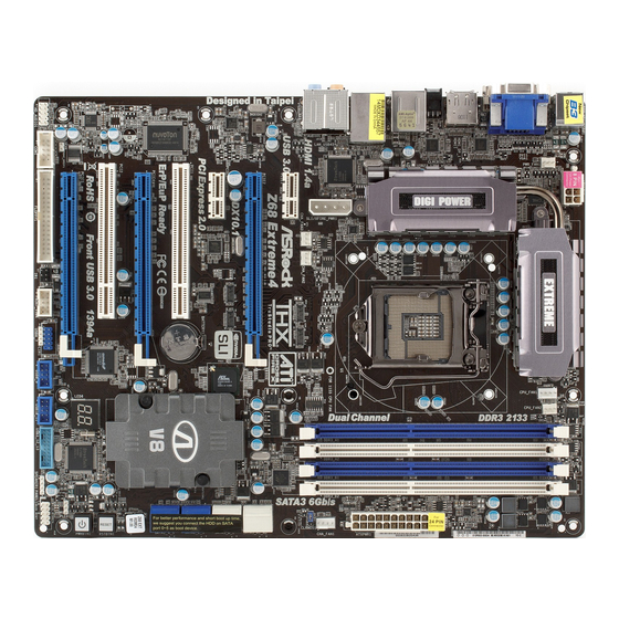
Seite 2: Motherboard-Layout
PCI Express 2.0 x1 Slot (PCIE1, White) Power Switch (PWRBTN) SLI / XFIRE Power Connector Power LED Header (PLED1) Chassis Fan Connector (CHA_FAN3) System Panel Header (PANEL1, White) Chassis Fan Connector (CHA_FAN2) Chassis Speaker Header (SPEAKER 1, White) ASRock Z68 Extreme4 Motherboard... - Seite 3 See the table below for connection details in accordance with the type of speaker you use. TABLE for Audio Output Connection Audio Output Channels Front Speaker Rear Speaker Central / Bass Line In or (No. 10) (No. 7) (No. 6) Side Speaker (No. 9) ASRock Z68 Extreme4 Motherboard...
- Seite 4 “ok”. Choose “2CH”, “4CH”, “6CH”, or “8CH” and then you are allowed to select “Realtek HDA Primary output” to use Rear Speaker, Central/Bass, and Front Speaker, or select “Realtek HDA Audio 2nd output” to use front panel audio. *** eSATA3 connector supports SATA Gen3 in cable 1M. ASRock Z68 Extreme4 Motherboard...
- Seite 5 In case any modifi cations of this manual occur, the updated version will be available on ASRock website without further notice. You may fi nd the latest VGA cards and CPU support lists on ASRock website as well.
-
Seite 6: Specifications
- Supports DisplayPort with max. resolution up to 2560x1600 @ 60Hz - Supports Auto Lip Sync, Deep Color (12bpc), xvYCC and HBR (High Bit Rate Audio) with HDMI (Compliant HDMI monitor is required) (see CAUTION 7) ASRock Z68 Extreme4 Motherboard... - Seite 7 - 2 x Rear USB 3.0 ports by Etron EJ168A, support USB 1.0/ 2.0/3.0 up to 5Gb/s - 1 x Front USB 3.0 header (supports 2 USB 3.0 ports) by Etron EJ168A, supports USB 1.0/2.0/3.0 up to 5Gb/s ASRock Z68 Extreme4 Motherboard...
- Seite 8 - Drivers, Utilities, AntiVirus Software (Trial Version), ASRock Software Suite (CyberLink DVD Suite - OEM and Trial) Unique Feature - ASRock Extreme Tuning Utility (AXTU) (see CAUTION 9) - Instant Boot - ASRock Instant Flash (see CAUTION 10) - ASRock APP Charger (see CAUTION 11)
- Seite 9 - FCC, CE, WHQL - ErP/EuP Ready (ErP/EuP ready power supply is required) (see CAUTION 19) * For detailed product information, please visit our website: http://www.asrock.com WARNING Please realize that there is a certain risk involved with overclocking, including adjusting the setting in the BIOS, applying Untied Overclocking Technology, or using the third-party overclocking tools.
- Seite 10 6-channel, and 8-channel modes. Please check the table on page 3 for proper connection. ASRock Extreme Tuning Utility (AXTU) is an all-in-one tool to fi ne-tune different system functions in a user-friendly interface, which is including Hardware Monitor, Fan Control, Overclocking, OC DNA and IES. In Hardware Monitor, it shows the major readings of your system.
- Seite 11 10. ASRock Instant Flash is a BIOS fl ash utility embedded in Flash ROM. This convenient BIOS update tool allows you to update system BIOS ® without entering operating systems fi rst like MS-DOS or Windows . With this utility, you can press <F6> key during the POST or press <F2> key to BIOS setup menu to access ASRock Instant Flash.
- Seite 12 Intel’s suggestion, the EuP ready power supply must meet the standard of 5v standby power effi ciency is higher than 50% under 100 mA current consumption. For EuP ready power supply selection, we recommend you checking with the power supply manufacturer for more details. ASRock Z68 Extreme4 Motherboard...
-
Seite 13: Installation
CPU surface is unclean or if there is any bent pin on the socket. Do not force to insert the CPU into the socket if above situation is found. Other- wise, the CPU will be seriously damaged. ASRock Z68 Extreme4 Motherboard... - Seite 14 Pin1 Pin1 alignment key 1155-Pin Socket orientation key notch 1155-Pin CPU For proper inserting, please ensure to match the two orientation key notches of the CPU with the two alignment keys of the socket. ASRock Z68 Extreme4 Motherboard...
- Seite 15 Please be noticed that this motherboard supports Combo Cooler Option (C.C.O.), which provides the fl exible option to adopt three dif- ferent CPU cooler types, Socket LGA 775, LGA 1155 and LGA 1156. The white throughholes are for Socket LGA 1155/1156 CPU fan. ASRock Z68 Extreme4 Motherboard...
- Seite 16 It is not allowed to install a DDR or DDR2 memory module into DDR3 slot; otherwise, this motherboard and DIMM may be dam- aged. Some DDR3 1GB double-sided DIMMs with 16 chips may not work on this motherboard. It is not recommended to install them on this motherboard. ASRock Z68 Extreme4 Motherboard...
- Seite 17 DIMM if you force the DIMM into the slot at incorrect orientation. Step 3. Firmly insert the DIMM into the slot until the retaining clips at both ends fully snap back in place and the DIMM is properly seated. ASRock Z68 Extreme4 Motherboard...
- Seite 18 Align the card connector with the slot and press fi rmly until the card is completely seated on the slot. Step 5. Fasten the card to the chassis with screws. Step 6. Replace the system cover. ASRock Z68 Extreme4 Motherboard...
- Seite 19 PCIE2 slot and the other graphics card to PCIE4 slot. Make sure that the cards are properly seated on the slots. Step2. If required, connect the auxiliary power source to the PCI Express graphics cards. ASRock Z68 Extreme4 Motherboard...
- Seite 20 Step3. Align and insert ASRock SLI_Bridge_2S Card to the goldfi ngers on each graphics card. Make sure ASRock SLI_Bridge_2S Card is fi rmly in place. ASRock SLI_Bridge_2S Card Step4. Connect a VGA cable or a DVI cable to the monitor connector or the DVI connector of the graphics card that is inserted to PCIE2 slot.
- Seite 21 Quad SLI feature. ® * SLI appearing here is a registered trademark of NVIDIA Technologies Inc., and is used only for identifi cation or explanation and to the owners’ benefi t, without intent to infringe. ASRock Z68 Extreme4 Motherboard...
- Seite 22 Step 1. Insert one Radeon graphics card into PCIE2 slot and the other Radeon graphics card to PCIE4 slot. Make sure that the cards are properly seated on the slots. ASRock Z68 Extreme4 Motherboard...
- Seite 23 Connect the DVI monitor cable to the DVI connector on the Radeon graphics card on PCIE2 slot. (You may use the DVI to D-Sub adapter to convert the DVI connector to D-Sub interface, and then connect the D-Sub monitor cable to the DVI to D-Sub adapter.) ASRock Z68 Extreme4 Motherboard...
- Seite 24 PCIE4 slots, and use the other CrossFire Bridge to connect Radeon graphics cards on PCIE4 and PCIE5 slots. (CrossFire Bridge is provided with the graphics card you purchase, not bundled with this motherboard. Please refer to your graphics card vendor for details.) ASRock Z68 Extreme4 Motherboard...
- Seite 25 Connect the DVI monitor cable to the DVI connector on the Radeon graph- ics card on PCIE2 slot. (You may use the DVI to D-Sub adapter to convert the DVI connector to D-Sub interface, and then connect the D-Sub monitor cable to the DVI to D-Sub adapter.) ASRock Z68 Extreme4 Motherboard...
- Seite 26 Double-click “ATI Catalyst Control Center”. Click “View”, select “CrossFi- ”, and then check the item “Enable CrossFireX ”. Select “2 GPUs” and click “Apply” (if you install two Radeon graphics cards). Select “3 GPUs” and click “OK” (if you install three Radeon graphics cards). ASRock Z68 Extreme4 Motherboard...
- Seite 27 Technologies Inc., and is used only for identifi cation or explanation and to the owners’ benefi t, without intent to infringe. * For further information of ATI CrossFireX technology, please check AMD website for updates and details. ASRock Z68 Extreme4 Motherboard...
- Seite 28 If you haven’t installed onboard VGA driver yet, please install onboard VGA driver from our support CD to your system and restart your computer. D-Sub, DVI-D, HDMI and DisplayPort monitors cannot be enabled at the same time. You can only choose two of them. ASRock Z68 Extreme4 Motherboard...
- Seite 29 F. Set the “Screen Resolution” and “Color Quality” as appropriate for the second monitor. Click “Apply” or “OK” to apply these new values. G. Repeat steps C through E for the diaplay icon identifi ed by the number one to eight. ASRock Z68 Extreme4 Motherboard...
- Seite 30 HDTV set-top-boxes, as well as few entertainment PCs requires a secure connection to a compliant display. Due to the increase in manufacturers employing HDCP in their equipment, it is highly recommended that the HDTV or LCD monitor you purchase is compatible. ASRock Z68 Extreme4 Motherboard...
- Seite 31 The Multi-Angle CIR Receiver does not support Hot-Plug function. Please install it before you boot the system. * ASRock Smart Remote is only supported by some of ASRock motherboards. Please refer to ASRock website for the motherboard support list: http://www.asrock.com...
- Seite 32 Please be noted that the password, date, time, user default profi le, 1394 GUID and MAC address will be cleared only if the CMOS battery is removed. The Clear CMOS Switch has the same function as the Clear CMOS jumper. ASRock Z68 Extreme4 Motherboard...
- Seite 33 SATA power cable to the power connector on each drive. (Optional) connect to the SATA Then connect the white end of HDD power connector SATA power cable to the power connect to the power supply connector of the power supply. ASRock Z68 Extreme4 Motherboard...
- Seite 34 (5-pin IR1) DUMMY and receiving infrared module. (see p.2 No. 33) IRRX Consumer Infrared Module Header This header can be used to connect the remote (4-pin CIR1) IRTX IRRX controller receiver. (see p.2 No. 31) ATX+5VSB ASRock Z68 Extreme4 Motherboard...
- Seite 35 The LED keeps blinking when the sys- tem is in S1 sleep state. The LED is off when the system is in S3/S4 sleep state or powered off (S5). ASRock Z68 Extreme4 Motherboard...
- Seite 36 (3-pin PWR_FAN1) +12V (see p.2 No. 2) CPU Fan Connectors Please connect the CPU fan FAN_SPEED_CONTROL cable to the connector and (4-pin CPU_FAN1) CPU_FAN_SPEED +12V match the black wire to the (see p.2 No. 4) ground pin. ASRock Z68 Extreme4 Motherboard...
- Seite 37 SLI/XFIRE Power Connector It is not necessary to use this connector, but please connect it (4-pin SLI/XFIRE_PWR1) with a hard disk power (see p.2 No. 45) connecor when two graphics SLI/XFIRE_POWER1 cards are plugged to this motherboard. ASRock Z68 Extreme4 Motherboard...
- Seite 38 HDD screws, and six chassis screws. Step 3 Screw the Front USB 3.0 Panel to the Step 4 Intall the Front USB 3.0 Panel into the 2.5” drive bay with six chassis screws. drive bay of the chassis. ASRock Z68 Extreme4 Motherboard...
- Seite 39 Put the USB 3.0 cable and the rear Panel. USB 3.0 bracket together. Step 4 Step 3 Screw the two screws into the rear USB 3.0 Put the rear USB 3.0 bracket into the bracket. chassis. ASRock Z68 Extreme4 Motherboard...
- Seite 40 (RSTBTN) RESET the system. (see p.2 No. 21) Clear CMOS Switch Clear CMOS Switch is a smart switch, allowing users to quickly (CLRCBTN) CMOS clear the CMOS values. (see p.3 No. 15) ASRock Z68 Extreme4 Motherboard...
- Seite 41 CPU post-memory initialization is started 0x33 CPU post-memory initialization. Cache initialization 0x34 CPU post-memory initialization. Application Processor(s) (AP) initialization 0x35 CPU post-memory initialization. Boot Strap Processor (BSP) selection 0x36 CPU post-memory initialization. System Management Mode (SMM) initialization ASRock Z68 Extreme4 Motherboard...
- Seite 42 Reserved for future AMI progress codes 0xF8 Recovery PPI is not available 0xF9 Recovery capsule is not found 0xFA Invalid recovery capsule 0xFB – 0xFF Reserved for future AMI error codes 0x60 DXE Core is started 0x61 NVRAM initialization ASRock Z68 Extreme4 Motherboard...
- Seite 43 0x9C USB Detect 0x9D USB Enable 0x9E – 0x9F Reserved for future AMI codes 0xA0 IDE initialization is started 0xA1 IDE Reset 0xA2 IDE Detect 0xA3 IDE Enable 0xA4 SCSI initialization is started 0xA5 SCSI Reset ASRock Z68 Extreme4 Motherboard...
- Seite 44 No Console Input Devices are found 0xD8 Invalid password 0xD9 Error loading Boot Option (LoadImage returned error) 0xDA Boot Option is failed (StartImage returned error) 0xDB Flash update is failed 0xDC Reset protocol is not available ASRock Z68 Extreme4 Motherboard...
- Seite 45 B. Set the option “SATA Mode” to [IDE]. (For SATA3_0, SATA3_1 and SATA2_2 to SATA2_5 ports.) Set the option “Marvell SATA3 Operation Mode” to [IDE]. (For SATA3_M1 and SATA3_M2 ports.) ® STEP 2: Install Windows XP / XP 64-bit OS on your system. ASRock Z68 Extreme4 Motherboard...
- Seite 46 B. Set the option “SATA Mode” to [AHCI]. (For SATA3_0, SATA3_1 and SATA2_2 to SATA2_5 ports.) Set the option “Marvell SATA3 Operation Mode” to [AHCI]. (For SATA3_M1 and SATA3_M2 ports.) ® STEP 2: Install Windows 7 / 7 64-bit / Vista / Vista 64-bit OS on your system. ASRock Z68 Extreme4 Motherboard...
- Seite 47 It will display the Main Menu automatically if “AUTORUN” is enabled in your computer. If the Main Menu does not appear automatically, locate and double-click on the fi le “ASSETUP.EXE” from the BIN folder in the Support CD to display the menus. ASRock Z68 Extreme4 Motherboard...
- Seite 48 1. Einführung Wir danken Ihnen für den Kauf des ASRock Z68 Extreme4 Motherboard, ein zu- verlässiges Produkt, welches unter den ständigen, strengen Qualitätskontrollen von ASRock gefertigt wurde. Es bietet Ihnen exzellente Leistung und robustes Design, gemäß der Verpflichtung von ASRock zu Qualität und Halbarkeit. Diese Schnel- linstallationsanleitung führt in das Motherboard und die schrittweise Installation...
- Seite 49 1920 x 1200 bei 60 Hz - Unterstützt DVI mit einer maximalen Aufl ösung von 1920 x 1200 bei 60 Hz - Unterstützt D-Sub mit einer maximalen Aufl ösung von 2048 x 1536 bei 75 Hz ASRock Z68 Extreme4 Motherboard...
- Seite 50 (RAID 0, RAID 1, RAID 10, RAID 5, Intel Rapid Storage und Intel Smart Response-Technologie), NCQ-, AHCI-und „Hot Plug“ (Hot-Plugging)-Funktionen - 2 x SATA 3-Anschlüsse (6,0 Gb/s) durch Marvell SE9120; unterstützt NCQ-, AHCI-und „Hot Plug“ (Hot-Plugging)- Funktionen (SATA3_M2-Anschluss wird mit dem eSATA 3-Port geteilt) ASRock Z68 Extreme4 Motherboard...
- Seite 51 - ACPI 1.1-Weckfunktionen - JumperFree-Übertaktungstechnologie - SMBIOS 2.3.1 - CPU Core, IGPU, DRAM, PCH, CPU PLL, VTT, VCCSA Stromspannung Multianpassung Support-CD - Treiber, Dienstprogramme, Anti-Virus-Software (Testversion), ASRock Software Suite (CyberLink DVD Suite – OEM- und Testversion) ASRock Z68 Extreme4 Motherboard...
- Seite 52 Einzigartige - ASRock Extreme Tuning Utility (AXTU) (siehe VORSICHT 9) Eigenschaft - Sofortstart - ASRock Instant Flash (siehe VORSICHT 10) - ASRock APP Charger (siehe VORSICHT 11) - SmartView (siehe VORSICHT 12) - ASRock XFast USB (siehe VORSICHT 13) - Lucid Virtu (siehe VORSICHT 14)
- Seite 53 Per IES (Intelligent Energy Saver) kann der Spannungsregulator bei Inaktivität der CPU-Kerne die Anzahl an Ausgangsphasen zur Steigerung der Effi zienz reduzieren – ohne die Rechenleistung zu beeinträchtigen. Hinweise zur Bedienung der ASRock Extreme Tuning Utility (AXTU) fi nden Sie auf unserer Webseite. ASRock-Webseite: http://www.asrock.com...
- Seite 54 APP Charger. Installieren Sie einfach den ASRock APP Charger-Treiber; dadurch lädt sich Ihr iPhone wesentlich schneller über einen Computer auf – genaugenommen bis zu 40 % schneller als zuvor. Der ASRock APP Charger ermöglicht Ihnen die schnelle Aufl adung mehrerer Apple-Geräte gleichzeitig;...
- Seite 55 15. Durch die ASRock ein/aus-Wiedergabetechnologie können Sie großar- tige Klangerlebnisse von portablen Audiogeräten, wie z. B. MP3-Playern oder Mobiltelefonen, an Ihrem PC genießen – selbst wenn der PC ausge- schaltet ist (oder sich im ACPI S5-Modus befi ndet)! Dieses Motherboard wird zudem mit einem kostenlosen Audiokabel (3,5 mm, Klinke) (optional) geliefert, was eine IT-Umgebung von höchster Benutzerfreundlichkeit...
- Seite 56 Bevor Sie die 1155-Pin CPU in den Sockel sitzen, prüfen Sie bitte, ob die CPU-Oberfl äche sauber ist und keine der Kontakte verbogen sind. Setzen Sie die CPU nicht mit Gewalt in den Sockel, dies kann die CPU schwer beschädigen. ASRock Z68 Extreme4 Motherboard...
- Seite 57 Schritt 3-2. Halten Sie das Teil mit dem IHS (Integrated Heat Sink – integ- rierter Kühlkörper) nach oben. Suchen Sie Pin 1 und die zwei Orientierungseinkerbungen. Ausrichtungsmarkierung Orientierungskerbe Pin1 Pin1 Ausrichtungsmarkierung Orientierungskerbe 1155-Pin Sockel 1155-Pin CPU ASRock Z68 Extreme4 Motherboard...
- Seite 58 Schritt 4. Sockel schließen: Schritt 4-1. Drehen Sie die Ladeplatte auf den Kühlkörper (IHS). Schritt 4-2. Drücken Sie leicht auf die Lade- platte und schließen Sie den Ladehebel. Schritt 4-3. Sichern Sie Ladehebel und Ladeplatte mithilfe des Hebelver- schlusses. ASRock Z68 Extreme4 Motherboard...
- Seite 59 Beachten Sie bitte, dass dieses Motherboard die Combo-Kühlerop- tion unterstützt, die eine fl exible Möglichkeit zur Aufnahme von drei verschiedenen CPU-Kühlertypen, Socket LGA 775, LGA 1155 und LGA 1156, bietet. Das weiße Durchgangsloch ist für den CPU-Lüfter im Socket LGA 1155/1156 vorgesehen. ASRock Z68 Extreme4 Motherboard...
- Seite 60 2.3 Installation der Speichermodule (DIMM) Die Motherboards Z68 Extreme4 bieten vier 240-pol. DDR3 (Double Data Rate 3) DIMM-Steckplätze und unterstützen die Dual-Kanal-Speichertechnologie. Für die Dual-Kanalkonfi guration dürfen Sie nur identische (gleiche Marke, Geschwindigkeit, Größe und gleicher Chiptyp) DDR3 DIMM-Paare in den Steckplätzen gleicher Farbe installieren.
- Seite 61 Steckplätze zu zwingen, führt dies zu dauerhaften Schäden am Mainboard und am DIMM-Modul. Schritt 3: Drücken Sie die DIMM-Module fest in die Steckplätze, so dass die Halteklammern an beiden Enden des Moduls einschnappen und das DIMM-Modul fest an Ort und Stelle sitzt. ASRock Z68 Extreme4 Motherboard...
- Seite 62 Erweiterungssteckplätze (PCI-Steckplätze und PCI Express-Steckplätze) Es gibt einen 2 PCI-Steckplätze und 5 PCI Express-Steckplätze am Z68 Extreme4 Motherboard. PCI-Slots: PCI-Slots werden zur Installation von Erweiterungskarten mit dem 32bit PCI-Interface genutzt. PCI Express-Slots: PCIE1 / PCIE3 (PCIE x1-Steckplatz; Weiß) wird für PCI Express-Karten mit x1 Lane-Breite-Karten verwendet, z.B.
- Seite 63 -und Quad CrossFireX -Funktion wird nur vom Betriebssys- ® tem Windows Vista / 7 unterstützt. Schauen Sie auf der AMD-Website nach, ob es ATI CrossFireX -Treiber-Updates gibt. Beachten Sie den detailliert erklärten Installationsablauf auf Seite 22. ASRock Z68 Extreme4 Motherboard...
- Seite 64 Der Fernbedienungsempfänger unterstützt kein Hot-Plugging. Bitte installieren Sie ihn, bevor Sie Ihr System hochfahren. * Die ASRock Smart Remote wird nur von einigen ASRock-Motherboards unterstützt. Eine Liste dieser Motherboards fi nden Sie auf der ASRock-Webseite: http://www.asrock.com ASRock Z68 Extreme4 Motherboard...
- Seite 65 CMOS-Löschung herunter. Bitte beachten Sie, dass Kennwort, Datum, Uhrzeit, benutzerdefi niertes Profi l, 1394 GUID und MAC-Adresse nur gelöscht werden, wenn die CMOS-Batterie entfernt wird. Der CMOS löschen-Schalter hat dieselbe Funktion wie der CMOS löschen-Jumper. ASRock Z68 Extreme4 Motherboard...
- Seite 66 Datenübertragungsrate bis 6,0 Gb/s. Serial ATA- (SATA-) SJedes Ende des SATA Datenkabel Datenkabels kann an die SATA / SATAII / SATA3 Festplatte (Option) oder das SATAII / SATA3 Verbindungsstück auf dieser Hauptplatine angeschlossen werden. ASRock Z68 Extreme4 Motherboard...
- Seite 67 IntA_P2_SSTX- befi ndet sich ein USB 3.0- (siehe S.2 - No. 26) IntA_P2_SSRX+ IntA_P2_SSRX- Header an diesem Vbus Motherboard. Dieser USB 3.0- Header kann zwei USB 3.0- Vbus Ports unterstützen. IntA_P1_SSRX- IntA_P1_SSRX+ IntA_P1_SSTX- IntA_P1_SSTX+ IntA_P1_D- IntA_P1_D+ ASRock Z68 Extreme4 Motherboard...
- Seite 68 7 / 7 64 Bit / Vista / Vista 64 Bit: Wählen Sie im Realtek-Bedienfeld die „FrontMic“ (Vorderes Mikrofon)- Registerkarte. Passen Sie die „Recording Volume“ (Aufnahmelautstärke) System Panel-Header Dieser Header unterstützt mehrere Funktion der (9-pin PANEL1) Systemvorderseite. (siehe S.2 - No. 24) ASRock Z68 Extreme4 Motherboard...
- Seite 69 PLED- (siehe S.2 - No. 23) PLED+ PLED+ Systembetriebsstatus an diesem Header an. Die LED leuchtet, wenn das System in Betrieb ist. Die LED blinkt im S1-Zustand. Im S3-/S4- oder S5-Zustand (ausgeschaltet) leuchtet die LED nicht. ASRock Z68 Extreme4 Motherboard...
- Seite 70 Obwohl dieses Motherboard einen 24-pol. ATX- Stromanschluss bietet, kann es auch mit einem modifi zierten traditionellen 20-pol. ATX-Netzteil verwendet werden. Um ein 20-pol. ATX-Netzteil zu verwenden, stecken Sie den Stecker mit Pin 1 und Pin 13 ein. Installation eines 20-pol. ATX-Netzteils ASRock Z68 Extreme4 Motherboard...
- Seite 71 (siehe S.2 - No. 32) IEEE-1394 Header +12V (FRONT_1394) auf dieser RXTPBP_0 Hauptplatine. Dieser IEEE-1394 RXTPAP_0 Header kann einen IEEE-1394 Port unterstützen. COM-Anschluss-Header Dieser COM-Anschluss- Header wird verwendet, um (9-pin COM1) ein COM-Anschlussmodul zu (siehe S.2 - No. 35) unterstützen. ASRock Z68 Extreme4 Motherboard...
- Seite 72 Installieren Sie die USB 3.0-Frontblende im mit sechs Gehäuseschrauben am 2,5 Zoll-Festplatteneinschub des Gehäuses. Festplatteneinschub. Schritt 5 Schritt 6 Schließen Sie das Kabel der Die USB 3.0-Frontblende ist nun USB 3.0-Frontblende am USB 3.0-Header einsatzbereit. (USB3_12_13) am Motherboard an. ASRock Z68 Extreme4 Motherboard...
- Seite 73 (RSTBTN) RESET Benutzer das System schnell (siehe S.2 - No. 21) zurücksetzen können. CMOS löschen-Schalter Der CMOS löschen-Schalter ist ein Schnellschalter, mit dem (CLRCBTN) CMOS Benutzer die CMOS-Werte (siehe S.3 - No. 15) schnell löschen können. ASRock Z68 Extreme4 Motherboard...
- Seite 74 A. Rufen Sie das UEFI SETUP UTILITY auf, wählen Sie den „Advanced“- Bildschirm (Erweitert), dann „Storage Confi guration“. B. Stellen Sie “SATA Mode” auf [IDE]. (Für SATA3_0, SATA3_1 und SATA2_2 zu SATA2_5.) Stellen Sie “Marvell SATA3 Operation Mode” auf [IDE]. (Für SATA3_M1 zu SATA3_M2.) ASRock Z68 Extreme4 Motherboard...
- Seite 75 B. Stellen Sie “SATA Mode” auf [AHCI]. (Für SATA3_0, SATA3_1 und SATA2_2 zu SATA2_5.) Stellen Sie “Marvell SATA3 Operation Mode” auf [AHCI]. (Für SATA3_M1 zu SATA3_M2.) ® SCHRITT 2: Installieren Sie Windows 7 / 7 64-Bit / Vista / Vista 64-Bit in Ihrem System. ASRock Z68 Extreme4 Motherboard...
- Seite 76 ASSETUP.EXE im BIN-Verzeichnis der Support-CD, um die Menüs aufzurufen. Das Setup-Programm soll es Ihnen so leicht wie möglich machen. Es ist menüges- teuert, d.h. Sie können in den verschiedenen Untermenüs Ihre Auswahl treffen und die Programme werden dann automatisch installiert. ASRock Z68 Extreme4 Motherboard...
-
Seite 77: Contenu Du Paquet
1. Introduction Merci pour votre achat d’une carte mère ASRock Z68 Extreme4, une carte mère très fi able produite selon les critères de qualité rigoureux de ASRock. Elle offre des performances excellentes et une conception robuste conformément à l’engagement d’ASRock sur la qualité et la fi abilité au long terme. -
Seite 78: Spécifications
- Quatre options de sortie VGA: D-Sub, DVI-D, HDMI et DisplayPort (voir ATTENTION 6) - Prend en charge le HDMI 1.4a avec une résolution maximale jusqu’à 1920x1200 @ 60Hz - Prend en charge le DVI avec une résolution maximale jusqu’à 1920x1200 @ 60Hz ASRock Z68 Extreme4 Motherboard... - Seite 79 - 2 x connecteurs SATA3 6,0 Gb/s, prennent en charge les fonctions RAID (RAID 0, RAID 1, RAID 10, RAID 5, Intel Rapid Storage et Intel Smart Response), NCQ, AHCI et « Hot Plug » (Branche ment à chaud) ASRock Z68 Extreme4 Motherboard...
- Seite 80 - 1 x interrupteur de réinitialisation avec LED BIOS - 64Mb AMI BIOS - AMI UEFI Legal BIOS avec support GUI - Support du “Plug and Play” - Compatible pour événements de réveil ACPI 1.1 - Gestion jumperless - Support SMBIOS 2.3.1 ASRock Z68 Extreme4 Motherboard...
- Seite 81 - CPU Core, IGPU, DRAM, PCH, CPU PLL, VTT, VCCSA Tension Multi-ajustement CD d’assistance - Pilotes, utilitaires, logiciel anti-virus (version d’évaluation), suite logicielle ASRock (suite CyberLink DVD - OEM et version d’évaluation) Caractéristique - Utilitaire ASRock Extreme Tuning (AXTU) unique (voir ATTENTION 9) - l’Instant Boot...
- Seite 82 2-canaux, 4-canaux, 6-canaux et 8-canaux. Veuillez vous référer au tableau en page 3 pour effectuer la bonne connexion. ASRock Extreme Tuning Utility (AXTU) est un utilitaire tout-en-un qui permet de régler précisément différentes fonctions du système, via une interface facile à utiliser, incluant Moniteur de périphériques, Contrôle du ventilateur, Overclocking, OC DNA et IES.
- Seite 83 ASRock Extreme Tuning Utility (AXTU). Site Web de ASRock : http://www.asrock.com 10. O ASRock Instant Flash é um utilitário de fl ash do BIOS incorporado na memória Flash ROM. Esta prática ferramenta de actualização do BIOS permite-lhe actualizar o BIOS do sistema sem necessitar de entrar nos ®...
- Seite 84 13. ASRock XFast USB permet d’améliorer les performances de votre péri- phérique de stockage USB. Les performances réelles dépendent des propriétés du périphérique. 14. Avec la technologie Lucid Virtu, vous pouvez regarder les performances 3D du GPU discret et les fonctions multimédia avancées des graphiques ®...
- Seite 85 Si c’est le cas, ne forcez pas pour insérer le processeur dans le socket. Sinon, le processeur sera gravement endommagé. ASRock Z68 Extreme4 Motherboard...
- Seite 86 Etape 3-2. Orientez le paquet avec le dissipa- teur thermique intégré (IHS) vers le haut. Repérez la broche 1 et les deux encoches d’orientation. Encoche d’orientation Détrompeur broche 1 broche 1 Détrompeur Socket 1155 broches Encoche d’orientation Processeur 1155 broches ASRock Z68 Extreme4 Motherboard...
- Seite 87 L’exemple ci-dessous illustre l’installation du dissipateur thermique pour un proces- seur 1155 broches. Etape 1. Appliquez le matériau d’interface thermique (Appliquez le matériau au centre de IHS sur la surface du socket. d’interface thermique) Apply Thermal Interface Material ASRock Z68 Extreme4 Motherboard...
- Seite 88 Cooler Option (C.C.O.), qui offre un choix fl exible pour adopter trois types différents de refroidisseurs de CPU, les sockets LGA 775, LGA 1155 et LGA 1156. Les trous traversant blancs sont pour le ventila- teur de CPU au socket LGA 1155/1156. ASRock Z68 Extreme4 Motherboard...
- Seite 89 2.3 Installation des modules m émoire [DIMM] La carte mère Z68 Extreme4 dispose de quatre emplacements DIMM DDR3 (Double Data Rate 3) de 240-broches, et supporte la Technologie de Mémoire à Canal Double. Pour effectuer une confi guration à canal double, vous devez toujours instal- ler des paires de DIMM DDR3 identiques (de la même marque, de la même vitesse,...
- Seite 90 DIMM. Etape 3. Insérez fermement le module DIMM dans son emplacement jusqu’à ce que les clips de maintien situés aux deux extrémités se ferment complètement et que le module DIMM soit inséré correctement. ASRock Z68 Extreme4 Motherboard...
- Seite 91 Slot d’extension (Slots PCI et Slots PCI Express) Il y a 2 ports PCI et 5 ports PCI Express sur la carte mère Z68 Extreme4. Slots PCI: Les slots PCI sont utilisés pour installer des cartes d’extension dotées d’une interface PCI 32 bits.
- Seite 92 Windows Vista / 7 uniquement. Veuillez consulter le site d’AMD pour les mises à jour de driver ATI CrossFireX . Veuillez suivre les instructions d’installation de la page 22 pour plus de détails. ASRock Z68 Extreme4 Motherboard...
- Seite 93 à chaud en charge. Veuillez l’installer avant de démarrer le système. * La télécommande ASRock n'est prise en charge que par certaines cartes mères of ASRock. Pour la liste des cartes mères prises en charge, veuillez vous reporter au site web ASRock : http://www.asrock.com ASRock Z68 Extreme4 Motherboard...
- Seite 94 Le fait de placer les capuchons de cavalier sur les en-têtes et connecteurs causera à la carte mère des dommages irréversibles! Connecteur du lecteur de disquette (FLOPPY1 br. 33) (voir p.2 No. 34) le côté avec fi l rouge côté Broche1 ASRock Z68 Extreme4 Motherboard...
- Seite 95 Connectez ensuite l’extrémité c o n n e c t e r à d’alimentation du blanche du cordon l’unité disque d’alimentation d’alimentation SATA sur le dur SATA électrique connecteur d’alimentation de l’unité d’alimentation électrique. ASRock Z68 Extreme4 Motherboard...
- Seite 96 Vbus IntA_P1_SSRX- IntA_P1_SSRX+ IntA_P1_SSTX- IntA_P1_SSTX+ IntA_P1_D- IntA_P1_D+ En-tête du module infrarouge Cet en-tête supporte un module IRTX +5VSB infrarouge optionnel de DUMMY (IR1 br.5) transfert et de réception sans (voir p.2 No. 33) fi l. IRRX ASRock Z68 Extreme4 Motherboard...
- Seite 97 (voir p.2 No. 24) Connectez l’interrupteur d’alimentation, l’interrupteur de réinitialisation et l’indicateur d’état du système du châssis sur cette barrette en respectant l’affectation des broches décrite ci-dessous. Faites attention aux broches positives et négatives avant de connecter les câbles. ASRock Z68 Extreme4 Motherboard...
- Seite 98 Connecteur pour châssis et ventilateur Branchez les câbles du ventilateur aux connecteurs pour (CHA_FAN1 br. 4) FAN_SPEED_CONTROL CHA_FAN_SPEED (voir p.2 No. 9) ventilateur et faites correspondre +12V le fi l noir à la broche de terre. ASRock Z68 Extreme4 Motherboard...
- Seite 99 Pour utiliser une alimentation ATX 20 broches, branchez à l’alimentation électrique ainsi qu’aux broches 1 et 13. 20-Installation de l’alimentation électrique ATX Connecteur ATX 12V Veuillez connecter une unité d’alimentation électrique ATX (ATX12V1 br.8) 12V sur ce connecteur. (voir p.2 No. 1) ASRock Z68 Extreme4 Motherboard...
- Seite 100 SPDIFOUT (voir p.2 No. 37) et permettant au système de se connecter au un téléviseur numérique HDMI /un projecteur / un périphérique LCD. Veuillez brancher le connecteur HDMI_SPDIF de la carte VGA HDMI sur ce connecteur. ASRock Z68 Extreme4 Motherboard...
- Seite 101 Assemblez le câble USB 3.0 et le avant USB 3.0. support arrière USB 3.0. Étape 3 Étape 4 Vissez les deux vis dans le support Placez le support arrière USB 3.0 arrière USB 3.0. dans le châssis. ASRock Z68 Extreme4 Motherboard...
- Seite 102 à l’utilisateur de réinitialiser rapidement le système. Interrupteur d’effacement de CMOS L’interrupteur d’effacement de (CLRCBTN) CMOS est un interrupteur rapide (voir p.3 No. 15) qui permet à l’utilisateur d’effacer CMOS rapidement les valeurs du CMOS. ASRock Z68 Extreme4 Motherboard...
- Seite 103 A. Accédez à UEFI SETUP UTILITY (Utilitaire de confi guration UEFI) → écran Avancé → Confi guration Storage. B. Réglez «SATA Mode « sur [IDE]. (Pour SATA3_0, SATA3_1 et SATA2_2 à SATA2_5.) Réglez «Marvell SATA3 Operation Mode « sur [IDE]. (Pour SATA3_M1 à SATA3_M2.) ASRock Z68 Extreme4 Motherboard...
- Seite 104 B. Réglez «SATA Mode « sur [AHCI]. (Pour SATA3_0, SATA3_1 et SATA2_2 à SATA2_5.) Réglez «Marvell SATA3 Operation Mode « sur [AHCI]. (Pour SATA3_M1 à SATA3_M2.) ® ETAPE 2: Installer le système d’exploitation Windows 7 / 7 64-bit / Vista / Vista 64-bit sur votre système. ASRock Z68 Extreme4 Motherboard...
- Seite 105 CD-ROM. Le Menu principal s’affi che automatiquement si “AUTORUN” est activé dans votre ordinateur. Si le Menu principal n’apparaît pas automatiquement, locali- sez dans le CD technique le fi chier “ASSETUP.EXE” dans le dossier BIN et double- cliquez dessus pour affi cher les menus. ASRock Z68 Extreme4 Motherboard...
-
Seite 106: Contenuto Della Confezione
1. Introduzione Grazie per aver scelto una scheda madre ASRock Z68 Extreme4, una scheda madre affi dabile prodotta secondo i severi criteri di qualità ASRock. Le prestazioni eccellenti e il design robusto si conformano all’impegno di ASRock nella ricerca della qualità e della resistenza. - Seite 107 - Supporta DVI con risoluzione massima fi no a 1920x1200 @ 60Hz - Supporta D-Sub con risoluzione massima fi no a 2048x1536 @ 75Hz - Supporta DisplayPort con risoluzione massima fi no a 2560x1600 @ 60Hz ASRock Z68 Extreme4 Motherboard...
- Seite 108 - 2 x porte USB 3.0 posteriori amministrate dal controller Etron EJ168A, supporto di USB 1.0/2.0/3.0 fi no a 5Gb/s - 1 x header USB 3.0 frontale (supporta 2 porte USB 3.0) amministrato dal controller Etron EJ168A, supporto di USB 1.0/2.0/3.0 fi no a 5Gb/s ASRock Z68 Extreme4 Motherboard...
- Seite 109 - Regolazione multi-voltaggio CPU Core, IGPU, DRAM, PCH, CPU PLL, VTT, VCCSA CD di - Driver, Utilità, Software AntiVirus (versione di prova), Suite supporto Software ASRock (Suite DVD CyberLink - OEM e versione di prova) Caratteristica - ASRock Extreme Tuning Utility (AXTU) (vedi ATTENZIONE 9) speciale...
- Seite 110 - Predisposto ErP/EuP (è necessaria l’alimentazione predisposta per il sistema ErP/EuP) (vedi ATTENZIONE 19) * Per ulteriori informazioni, prego visitare il nostro sito internet: http://www.asrock.com AVVISO Si prega di prendere atto che la procedura di overclocking implica dei rischi, come anche la regolazione delle impostazioni del BIOS, l’applicazione della tecnologia...
- Seite 111 AXTU (ASRock Extreme Tuning Utility). Sito ASRock: http://www.asrock.com 10. ASRock Instant Flash è una utilità Flash BIOS integrata nella Flash ROM. Questo comodo strumento d’aggiornamento del BIOS permette di aggior- nare il sistema BIOS senza accedere a sistemi operativi come MS-DOS ®...
- Seite 112 ® diali avanzate delle grafi che 3D Intel 15. La tecnologia ASRock On/Off Play consente agli utenti di godere di una esperienza audio eccezionale tramite i dispositivi audio portatili come i lettori MP3 o il cellulare sul proprio PC, anche quando il PC è spento (op- pure in modalità...
-
Seite 113: Installazione
5. Nell’usare i giraviti per fi ssare la scheda madre al telaio non ser- rare eccessivamente le viti! Altrimenti si rischia di danneggiare la scheda madre. ASRock Z68 Extreme4 Motherboard... - Seite 114 Fase 3-1. Tenere la CPU dai bordi segnati con linee nere. Fase 3-2. Orientare il pacchetto con l’IHS (Integrated Heat Sink: dispersore di calore integrato) verso l’alto. Individuare il Pin1 ed i due dentelli chiave d’orientamento. ASRock Z68 Extreme4 Motherboard...
- Seite 115 Fase 4-2. Bloccare la leva di carico mentre si preme leggermente sulla piastra di carico. Fase 4-3. Fissare la leva di carico con la linguetta della piastra di carico che si trova sulla parte inferiore della linguetta di ritenzione della leva di carico. ASRock Z68 Extreme4 Motherboard...
- Seite 116 Cooler Option), che fornisce la fl essibilità di impiegare tre tipi diversi di dispersori di calore CPU, Socket LGA 775, LGA 1155 e LGA 1156. I fori di colore bianco sono per la ventola CPU Socket LGA 1155/1156. ASRock Z68 Extreme4 Motherboard...
- Seite 117 2.3 Installazione dei moduli di memoria (DIMM) La scheda madre Z68 Extreme4 fornisce quattro alloggiamenti DIMM DDR3 (Double Data Rate 3) a 240 pin, e supporta la tecnologia Dual Channel Memory. Per la confi gurazione a due canali, è necessario installare sempre coppie identiche (stessa marca, velocità, dimensioni e tipo di chip) di DIMM DDR3 negli alloggiamenti dello...
- Seite 118 DIMM stessa. Step 3. Inserire saldamente la DIMM nello slot fi no a far scattare completamente in posizione i fermagli di ritegno alle due estremità e fi no ad installare correttamente la DIMM nella sua sede. ASRock Z68 Extreme4 Motherboard...
- Seite 119 Slot di espansione (Slot PCI ed Slot PCI Express) Sulla scheda madre Z68 Extreme4 c’è 2 slot PCI ed 5 slot PCI Express. Slot PCI: Sono utilizzati per installare schede di espansione con Interfaccia PCI a 32-bit. Slot PCI Express: L’alloggio PCIE1 / PCIE3 (PCIE x1; bianco) è usato per le schede PCI Express x1 lane, come schede Gigabit LAN e SATA2.
- Seite 120 Quad CrossFireX è supportata solo dal sistema operati- ® vo Windows Vista / 7. Visitare il sito AMD per gli aggiornamenti dei driver ATI CrossFireX . Attenersi alle procedure d’installazione, a pagina 22, per i dettagli. ASRock Z68 Extreme4 Motherboard...
- Seite 121 ASRock Smart Remote Guida all'installazione rapida ASRock Smart Remote è usato solo con schede madre ASRock dotate di connettore CIR. Fare riferimento alle procedure che seguono per l'installazione rapida e l’uso di ASRock Smart Remote. Fase 1. Trovare il connettore CIR che si trova Connettore USB 2.0...
- Seite 122 1394 GUID e indirizzo MAC saranno cancellati solo se è rimossa la batteria della CMOS. L’interruttore Clear CMOS (Cancella CMOS) ha la stessa funzione del jumper Clear CMOS. ASRock Z68 Extreme4 Motherboard...
- Seite 123 Cavi dati Serial ATA (SATA) Una o altra estremità del cavo di dati SATA può essere (Opzionale) collegata al disco rigido SATA / SATAII / SATA3 o al connettore di SATAII / SATA3 su questa cartolina base. ASRock Z68 Extreme4 Motherboard...
- Seite 124 I/O, (19-pin USB3_12_13) IntA_P2_SSTX+ IntA_P2_SSTX- questa scheda madre è dotata (vedi p.2 Nr. 26) IntA_P2_SSRX+ IntA_P2_SSRX- di un header USB 3.0 che Vbus supporta due porte USB 3.0. Vbus IntA_P1_SSRX- IntA_P1_SSRX+ IntA_P1_SSTX- IntA_P1_SSTX+ IntA_P1_D- IntA_P1_D+ ASRock Z68 Extreme4 Motherboard...
- Seite 125 Andare alla scheda “FrontMic” (Microfono frontale) del pannello di controllo Realtek. Regolare la voce “Recording Volume” (Volume registrazione). Collettore pannello di sistema Questo collettore accomoda diverse funzioni di sistema (9-pin PANEL1) pannello frontale. (vedi p.2 Nr. 24) ASRock Z68 Extreme4 Motherboard...
- Seite 126 Il (vedi p.2 Nr. 23) PLED+ PLED+ LED è acceso quando il sistema è in funzione. Il LED continua a lampeggiare in stato S1. Il LED è spento in stato S3/S4 o S5 (spegnimento). ASRock Z68 Extreme4 Motherboard...
- Seite 127 ATX a 24 pin, ma può funzionare lo stesso se si adotta un alimentatore ATX a 20 pin. Per usare l’alimentatore ATX a 20 pin, collegare l’alimentatore con il Pin 1 e il Pin 13. Installazione dell’alimentatore ATX a 20 pin ASRock Z68 Extreme4 Motherboard...
- Seite 128 SPDIF su scheda (2-pin HDMI_SPDIF1) SPDIFOUT HDMI VGA, consente al (vedi p.2 Nr. 37) sistema di collegare dispositivi per TV digitale HDMI/proiettori/ LCD . Collegare il connettore HDMI_SPDIF della scheda VGA HDMI a questo header. ASRock Z68 Extreme4 Motherboard...
- Seite 129 Svitare le due viti dal pannello USB 3.0 Punto 2 Collegare il cavo USB 3.0 e il anteriore. supporto USB 3.0 posteriore. Punto 3 Punto 4 Avvitare le due viti nel supporto USB 3.0 Inserire il supporto USB 3.0 posteriore. posteriore nel telaio. ASRock Z68 Extreme4 Motherboard...
- Seite 130 (vedi p.2 Nr. 21) agli utenti di resettare rapidamente il sistema. Interruttore pulizia CMOS L’interruttore di pulizia CMOS è (CLRCBTN) un interruttore rapido che CMOS (vedi p.3 Nr. 15) consente agli utenti di cancellare velocemente i valori CMOS. ASRock Z68 Extreme4 Motherboard...
- Seite 131 B. Impostare “SATA Mode” su [IDE]. (Per SATA3_0, SATA3_1 e SATA2_2 a SATA2_5.) Impostare “Marvell SATA3 Operation Mode” su [IDE]. (Per SATA3_M1 a SATA3_M2.) ® Passo 2: Installazione di Windows XP / XP 64-bit sul sistema. ASRock Z68 Extreme4 Motherboard...
- Seite 132 B. Impostare “SATA Mode” su [AHCI]. (Per SATA3_0, SATA3_1 e SATA2_2 a SATA2_5.) Impostare “Marvell SATA3 Operation Mode” su [AHCI]. (Per SATA3_M1 a SATA3_M2.) ® Passo 2: Installazione di Windows 7 / 7 64-bit / Vista / Vista 64-bit sul sistema. ASRock Z68 Extreme4 Motherboard...
- Seite 133 Inserire il CD di supporto nel lettore CD-ROM. Se la funzione “AUTORUN” è attivata nel computer, apparirà automaticamente il Menù principale. Se il Menù principale non appare automaticamente, posizionarsi sul fi le “ASSETUP.EXE” nel CESTINO del CD di supporto e cliccare due volte per visualizzare i menù. ASRock Z68 Extreme4 Motherboard...
- Seite 134 1. Introducción Gracias por su compra de ASRock Z68 Extreme4 placa madre, una placa de con- fi anza producida bajo el control de calidad estricto y persistente. La placa madre provee realización excelente con un diseño robusto conforme al compromiso de calidad y resistencia de ASRock.
- Seite 135 - Admite HDMI 1.4a con una resolución máxima de 1920x1200 a 60 Hz - Admite DVI con una resolución máxima de 1920x1200 a 60 Hz - Admite D-Sub con una resolución máxima de 2048x1536 a 75 Hz ASRock Z68 Extreme4 Motherboard...
- Seite 136 Intel Smart Response), NCQ, AHCI y de “Hot Plug” (conexión en caliente) - 2 x conectores SATA3 de 6,0 Gb/s con chip Marvell SE9120 con funciones NCQ, AHCI y de “Hot Plug” (conexión en cali- ente) (los puertos SATA3_M2 y eSATA3 son compartidos) ASRock Z68 Extreme4 Motherboard...
- Seite 137 - Múltiple ajuste de CPU Core, IGPU, DRAM, PCH, CPU PLL, VTT, VCCSA Voltage CD de soport - Controladores, utilidades, software de antivirus (versión de prueba), ASRock Software Suite (CyberLink DVD Suite: versión OEM y de prueba) ASRock Z68 Extreme4 Motherboard...
- Seite 138 Característica - ASRock Extreme Tuning Utility (AXTU) (vea ATENCIÓN 9) Única - Instant Boot - ASRock Instant Flash (vea ATENCIÓN 10) - ASRock APP Charger (vea ATENCIÓN 11) - SmartView (vea ATENCIÓN 12) - ASRock XFast USB (vea ATENCIÓN 13) - Lucid Virtu (vea ATENCIÓN 14)
- Seite 139 2 canales, 4 canales, 6 canales y 8 canales. Consulte la tabla en la página 3 para una conexión correcta. ASRock Extreme Tuning Utility (AXTU) es una herramienta todo en uno que permite realizar ajustes precisos en diferentes funciones del sistema mediante una interfaz sencilla, que incluye supervisión de...
- Seite 140 Windows 7 / 7 64 bits / Vista / Vista bits y que la versión de su explorador es IE8. Sitio Web de ASRock: http://www.asrock.com/Feature/SmartView/index.asp 13. ASRock XFast USB puede aumentar el rendimiento de los dispositivos de almacenamiento USB.
- Seite 141 50% con un consumo de corriente de 100mA. Para seleccionar una fuente de alimentación que cumpla la directiva EuP, le recomendamos que consulte con el fabricante de la fuente de alimentación para obtener más detalles. ASRock Z68 Extreme4 Motherboard...
-
Seite 142: Instalación
CPU se encuentra limpia y no hay ninguna aguja torcida en el socket. No introduzca la CPU en el socket por la fuerza si se produce la situación anterior. Si lo hace, puede producir daños graves en la CPU. ASRock Z68 Extreme4 Motherboard... - Seite 143 Heat Sink) mirando hacia arriba. Busque la aguja 1 y las dos muescas de orientación. Muesca de orientación Tecla de alineación aguja 1 aguja 1 Tecla de alineación Muesca de orientación Socket de 1155 agujas CPU de 1155 agujas ASRock Z68 Extreme4 Motherboard...
- Seite 144 A continuación se ofrece un ejemplo para ilustrar la instalación del disipador para la CPU de 1155 agujas. (Aplique el material termal de Paso 1. Aplique el material termal de interfaz en el interfaz) centro del IHS de la superfi cie del socket. Apply Thermal Interface Material ASRock Z68 Extreme4 Motherboard...
- Seite 145 (C.C.O.), una opción fl exible que puede adaptarse a tres tipos de disipador de CPU diferentes, correspondientes a los zócalos LGA 775, LGA 1155 y LGA 1156. Los orifi cios perforados de color blanco están destinados al ventilador de CPU para zócalos LGA 1155/1156. ASRock Z68 Extreme4 Motherboard...
- Seite 146 2.3 Instalación de Memoria La placa Z68 Extreme4 ofrece cuatro ranuras DIMM DDR3 de 240 pines, y soporta Tecnología de Memoria de Doble Canal. Para la confi guración de doble canal, necesitará instalar siempre pares DIMM DDR3 idénticos (de la misma marca, velocidad, tamaño y tipo) en las ranuras del mismo color.
- Seite 147 DIMM. Paso 3. Inserte la DIMM con fi rmeza dentro de la ranura hasta que los clips de sujeción de ambos lados queden completamente introducidos en su sitio y la DIMM se haya asentado apropiadamente. ASRock Z68 Extreme4 Motherboard...
- Seite 148 Ranuras de Expansión (ranuras PCI y ranuras PCI Express) La placa madre Z68 Extreme4 cuenta con 2 ranuras PCI y 5 ranuras PCI Express. Ranura PCI: Para instalar tarjetas de expansión que tienen 32-bit Interface PCI. Ranura PCI Express: La ranura PCIE1 / PCIE3 (ranura PCIE x1, Blanco) se utiliza con tarjetas PCI Express con ancho de banda x1, como las tarjetas Gigabit LAN, y SATA2.
- Seite 149 / 7. Consulte el sitio web de AMD si desea obtener más información acerca de las actualizaciones de los controladores de ATI CrossFireX . Por favor, siga los procedimientos de instalación de la página 22 para conocer las instrucciones detalladas. ASRock Z68 Extreme4 Motherboard...
- Seite 150 Instálelo antes de poner en marcha el sistema. * El mando a distancia inteligente de ASRock solamente es compatible con algunas placas base de ASRock. Consulte el sitio Web de ASRock para obtener una lista de placas bases compatibles. http://www.asrock.com...
- Seite 151 (vea p.2, N. 34) la banda roja debe quedar en el mismo lado que el contacto 1 Atención: Asegúrese que la banda roja del cable queda situado en el mismo lado que el contacto 1 de la conexión. ASRock Z68 Extreme4 Motherboard...
- Seite 152 Cualquier extremo del cable de audio de 3,5 mm se puede (Opcional) conectar a los dispositivos de audio portátiles, como por ejemplo reproductores MP3 y teléfonos móviles, o al puerto Entrada de línea de su PC. ASRock Z68 Extreme4 Motherboard...
- Seite 153 (vea p.2, N. 33) wireless opcional. IRRX Base de conexiones del módulo de Esta base de conexiones se infrarrojos para el consumidor puede utilizar para conectar IRTX receptor remoto. (4-pin CIR1) IRRX ATX+5VSB (vea p.2, N. 31) ASRock Z68 Extreme4 Motherboard...
- Seite 154 PWRBTN (interruptor de alimentación): Conecte el interruptor de encendido situado en el panel frontal del chasis. Puede confi gurar la forma de apagar su sistema mediante el interruptor de alimentación. ASRock Z68 Extreme4 Motherboard...
- Seite 155 Por favor, conecte los cables del y alimentación ventilador a los conectores de FAN_SPEED_CONTROL CHA_FAN_SPEED ventilador, haciendo coincidir el (4-pin CHA_FAN1) +12V (vea p.2, N. 9) cable negro con la patilla de masa. (3-pin CHA_FAN2) (vea p.2, N. 47) ASRock Z68 Extreme4 Motherboard...
- Seite 156 20 pins tradicional. Para usar una fuente de alimentación ATX de 20 pins, por favor, conecte su fuente de alimentación usando los Pins 1 y 13. Instalación de una Fuente de Alimentación ATX de 20 Pins ASRock Z68 Extreme4 Motherboard...
- Seite 157 Este jefe de IEEE 1394 +12V RXTPBP_0 puede apoyar un puerto de RXTPAP_0 IEEE 1394. Cabezal del puerto COM Este cabezal del puerto COM se utiliza para admitir un (9-pin COM1) módulo de puerto COM. (vea p.2, N. 35) ASRock Z68 Extreme4 Motherboard...
- Seite 158 fi jación al chasis. Paso 5 Paso 6 Conecte el cable del Panel frontal USB 3.0 El Panel frontal USB 3.0 quedará así listo a la cabecera USB 3.0 (USB3_12_13) de la para su uso. placa base. ASRock Z68 Extreme4 Motherboard...
- Seite 159 CMOS. Conmutador de borrado de memoria CMOS El conmutador de encendido es (CLRCBTN) un conmutador rápido que (vea p.3, N. 15) permite al usuario encender / CMOS apagar rápidamente el sistema. ASRock Z68 Extreme4 Motherboard...
- Seite 160 RAID, por favor siga los pasos siguientes. Uso de dispositivos SATA / SATAII / SATA3 sin funciones NCQ PASO 1: Confi guración de la UEFI. A. Entre en UEFI SETUP UTILITY → Òpantalla Avanzada → Storage Confi guración. ASRock Z68 Extreme4 Motherboard...
- Seite 161 B. Confi gure la “SATA Mode” a [AHCI]. (Para SATA3_0, SATA3_1 y SATA2_2 a SATA2_5.) Confi gure la “Marvell SATA3 Operation Mode” a [AHCI]. (Para SATA3_M1 a SATA3_M2.) ® PASO 2: Instale Windows 7 / 7 64 bits / Vista / Vista 64 bits en su sistema. ASRock Z68 Extreme4 Motherboard...
- Seite 162 Para iniciar la instalación, ponga el CD en el lector de CD y se des- plegará el Menú Principal automáticamente si «AUTORUN» está habilitado en su computadora. Si el Menú Principal no aparece automáticamente, localice y doble-pulse en el ar- chivo “ASSETUP.EXE” para iniciar la instalación. ASRock Z68 Extreme4 Motherboard...
- Seite 163 1. Введение Благодарим вас за покупку материнской платы ASRock Z68 Extreme4 надежной материнской платы, изготовленной в соответствии с постоянно предъявляемыми ASRock жесткими требованиями к качеству. Она обеспечивает превосходную производительность и отличается отличной конструкцией, которые отражают приверженность ASRock качеству и долговечности.
- Seite 164 - Поддержка Auto Lip Sync, Deep Color (12 бит на цветовой канал), xvYCC и HBR (High Bit Rate Audio) через HDMI (необходим монитор с разъемом HDMI) (см. ОСТОРОЖНО, пункт 7) - Поддержка стандарта Blu-ray Stereoscopic 3D со спецификацией HDMI 1.4a ASRock Z68 Extreme4 Motherboard...
- Seite 165 Intel Smart Response), NCQ, AHCI и «горячего подключения» - 4 x разъема SATA3 6,0 Гбит/с - 1 x Порт гибкого диска - 1 x Разъем порта печати - 1 x Датчик пользовательского инфракрасного модуля - 1 x Колодка COM ASRock Z68 Extreme4 Motherboard...
- Seite 166 - SmartView (см. ОСТОРОЖНО, пункт 12) - ASRock XFast USB (см. ОСТОРОЖНО, пункт 13) - Lucid Virtu (см. ОСТОРОЖНО, пункт 14) - Технология ASRock для воспроизведения звука во включенном и выключенном состоянии (см. ОСТОРОЖНО, пункт 15) - Hybrid Booster: - плавная настройка частоты процессора...
- Seite 167 бит / 7. Функция Deep Color будет включена только в том случае, если монитор поддерживает функцию EDID (12-битные цветовые каналы). ® Функция HBR поддерживается только в Windows 7 64-бит / 7 / Vista бит / Vista ASRock Z68 Extreme4 Motherboard...
- Seite 168 ее производительности во время простоя ядер ЦПУ. Чтобы узнать, как работать с программой ASRock Extreme Tuning Utility (AXTU), посетите наш сайт в Интернете. Адрес сайта ASRock: http://www.asrock.com 10. ASRock Instant Flash – программа для прошивки BIOS, встроенная в Flash ROM. Данное средство для обновления BIOS умеет работать без ®...
- Seite 169 Vista / Vista 64 bit и браузере IE8. Веб-сайт ASRock: http://www.asrock. com/Feature/SmartView/index.asp 13. Функция ASRock XFast USB увеличивает скорость работы устройств USB. Рост скорости зависит от устройства. 14. Благодаря технологии Lucid Virtu вы можете одновременно наслаждаться преимуществами 3D-производительности дискретного графического...
-
Seite 170: Меры Предосторожности
в корпусе компьютера, не затягивайте их слишком сильно! Это может привести к повреждению материнской платы. Установка процессора Для установки процессора Intel в 1155-контактном корпусе выполните следующие действия. Прижимная Load Plate пластина Load Lever Корпус гнезда Матрица контактов Socket Body Contact Array Общий вид 1155-контактного гнезда ASRock Z68 Extreme4 Motherboard... - Seite 171 Шаг 3-2. Поверните корпус интегрированным радиатором вверх. Найдите контакт 1 и два ключевых выреза для ориентации. Ключевой вырез для ориентации Ключ выравнивания контакт 1 контакт 1 Ключ выравнивания Ключевой вырез для ориентации 1155-контактное гнездо 1155-контактный процессор ASRock Z68 Extreme4 Motherboard...
- Seite 172 стрелке, радиатор нельзя будет закрепить на материнской плате. Шаг 5. Подсоедините контактную колодку вентилятора к разъему вентилятора процессора на материнской плате. Шаг 6. Закрепите свободную часть кабеля с помощью стяжки, чтобы кабель не мог помешать работе вентилятора или соприкасаться с другими компонентами. ASRock Z68 Extreme4 Motherboard...
- Seite 173 Отверстия с белой каймой предназначены для установки кулеров под Socket LGA1155/1156. 2.3 Установка модулей памяти (DIMM) Материнская плата Z68 Extreme4 включает четыре 240-контактных гнезда DDR3 (Double Data Rate 3) DIMM и поддерживает технологию Dual Chan- nel Memory Technology. В двухканальной конфигурации необходимо всегда...
- Seite 174 ключами, делающими невозможной неправильную установку. Применение силы при попытке вставить модуль в гнездо в неправильной ориентации может привести к повреждению модуля и системной платы. Шаг 3. Плотно вставьте DIMM-модуль в гнездо – фиксаторы по обоим концам гнезда должны полностью защелкнуться. ASRock Z68 Extreme4 Motherboard...
- Seite 175 2.4 Гнезда расширения (PCI и PCI Express) Материнские платы Z68 Extreme4 включают 2 гнезда PCI и 5 гнездо PCI Ex- press. Гнезда PCI: Гнезда PCI предназначены для карт расширения с 32- разрядным интерфейсом PCI. Гнезда PCIE: Гнездо PCIE1 / PCIE3 (PCIE x1; Белый) используется...
- Seite 176 / 7. Функция 3-стороннем режиме CrossFi- и Quad CrossFireX поддерживается только с операционной системой ® Windows Vista / 7. Посетите веб-сайт AMD для обновления драйверов ATI CrossFireX . См. процедуры установки на стр. 22 для детальной информации. ASRock Z68 Extreme4 Motherboard...
- Seite 177 имеющихся в продаже корпусов. Приемник ДУ не поддерживает функцию «горячего» подключения. Приемник необходимо подключить перед загрузкой системы. * Пульт ДУ ASRock Smart работает только с некоторыми материнскими платами ASRock. Список поддерживаемых материнских плат см. на веб-сайте ASRock: http://www.asrock. ASRock Z68 Extreme4 Motherboard...
- Seite 178 Разъем дисковода гибких дисков (33-контактный FLOPPY1) la banda roja debe quedar en el (см. стр. 2, п. 34) mismo lado que el contacto 1 Примечание. Убедитесь, что сторона кабеля с красной полосой соответствует контакту 1 на разъеме. ASRock Z68 Extreme4 Motherboard...
- Seite 179 соединителей на его черном (дополнительно) конце с ответными подключите к соединителю соединителями питания на питания жесткого диска каждом из жестких дисков. подключите к интерфейса SATA Затем соедините белый источнику конец кабеля питания стандарта питания SATA с блоком питания. ASRock Z68 Extreme4 Motherboard...
- Seite 180 Vbus поддерживает два порта USB 3.0. Vbus IntA_P1_SSRX- IntA_P1_SSRX+ IntA_P1_SSTX- IntA_P1_SSTX+ IntA_P1_D- IntA_P1_D+ Колодка инфракрасного модуля Данная колодка позволяет IRTX +5VSB подключить дополнительный (5-контактный IR1) DUMMY модуль беспроводного (см. стр. 2, п. 33) инфракрасного приемопередатчика. IRRX ASRock Z68 Extreme4 Motherboard...
- Seite 181 (см. стр. 2, п. 24) Подключите к этому разъему кнопку питания, кнопку сброса и индикатор состояния системы на корпусе в соответствии с указанным ниже назначением контактов. При подключении кабелей необходимо соблюдать полярность положительных и отрицательных контактов. ASRock Z68 Extreme4 Motherboard...
- Seite 182 S5 (система выключена). Chassis и Power Fan-соединители Подключите кабели вентилятора (4-контактный CHA_FAN1) к соединителям и присоедините FAN_SPEED_CONTROL CHA_FAN_SPEED (см. стр. 2, п. 9) черный шнур к штырю +12V заземления. (3-контактный CHA_FAN2) (см. стр. 2, п. 47) ASRock Z68 Extreme4 Motherboard...
- Seite 183 ивает 24-штыревой разъем питания ATX, работа будет продолжаться, даже если адаптируется традиционный 20-штыревой разъем питания ATX. Для использования 20-штыревого разъема питания ATX вставьте источник питания вместе со штекером 1 и штекером 13. Установка 20-штыревого разъема питания ATX ASRock Z68 Extreme4 Motherboard...
- Seite 184 обеспечивает подачу выходного (2-контактный HDMI_SPDIF1) аудиосигнала на VGA-карту (см. стр. 2, п. 37) SPDIFOUT HDMI, что позволяет подключать к системе цифровые телевизоры, проекторы или жидкокристаллические панели HDMI. Соедините эту колодку с разъемом HDMI_SPDIF на VGA- карте HDMI. ASRock Z68 Extreme4 Motherboard...
- Seite 185 в отсеке накопителя с помощью шести отсек 2,5”-накопителя на шасси. винтов. Шаг 5 Шаг 6 Подключите кабель передней панели Передняя панель USB 3.0 готова к USB 3.0 к монтажной колодке порта использованию. USB 3.0 (USB3_12_13) на материнской плате. ASRock Z68 Extreme4 Motherboard...
- Seite 186 систему. Reset Switch Кнопка Reset Switch позволяет (RSTBTN) быстро перезагрузить систему. RESET (см. стр. 2, п. 21) Clear CMOS Switch Кнопка Clear CMOS Switch (CLRCBTN) позволяет быстро сбросить (см. стр. 3, п. 15) CMOS установки CMOS. ASRock Z68 Extreme4 Motherboard...
- Seite 187 Использование жестких дисков SATA / SATAII / SATA3 без функций NCQ и горячего подключения ШАГ 1. Установите параметры UEFI. A. Войдите в утилиту настройки UEFI → экран Advanced → Storage Confi guration. B. Установите для “SATA Mode” значение [IDE]. (Для SATA3_0, SATA3_1 и SATA2_2 к SATA2_5) ASRock Z68 Extreme4 Motherboard...
- Seite 188 B. Установите для “SATA Mode” значение [AHCI]. (Для SATA3_0, SATA3_1 и SATA2_2 к SATA2_5) Установите для “Marvell SATA3 Operation Mode” значение [AHCI]. (Для SATA3_M1 к SATA3_M2.) ® ШАГ 2. Установите на свою систему Windows 7 / 7 64-bit / Vista Vista 64-bit. ASRock Z68 Extreme4 Motherboard...
- Seite 189 Если в вашем компьютере включена функция автозапуска (AUTORUN), то на экране автоматически появится главное меню компакт-диска (Main Menu). Если этого не произошло, найдите в папке BIN на компакт-диске поддержки файл ASSETUP.EXE и дважды щелкните на нем, чтобы открыть меню. ASRock Z68 Extreme4 Motherboard...
- Seite 190 önceden haber verilmeksizin değişebilir. Bu belgede değişiklik yapılması durumun -da, güncelleştirilmiş sürüm ayrıca haber verilmeksizin ASRock web sitesinde sunulur. En son VGA kartlarını ve CPU destek listelerini de ASRock web sitesinde bulabilirsiniz. ASRock web sitesi http://www.asrock.com Bu anakartla ilgili teknik desteğe ihtiyacınız olursa, kullandığınız modele özel bilgiler için lütfen web sitemizi ziyaret edin.
- Seite 191 - 75Hz’de 2048x1536’ya kadar maks. зцzьnьrlьkle D-Sub’э destekler - 60Hz’de 2560x1600’ya kadar maks. зцzьnьrlьkle DisplayPort’э destekler - Auto Lip Sync, Deep Color (12bpc), HDMI ile xvYCC ve HBR’yi (Yьksek Bit Hэzlэ Ses) destekler (Uyumlu HDMI monitцr gerekir) (bkz. DЭKKAT 7) ASRock Z68 Extreme4 Motherboard...
- Seite 192 USB 3.0 bağlantı noktasını destekler), 5Gb/s’ye kadar USB 1.0/2.0/3.0 Konektör - 4 x SATA2 3,0Gb/sn, donanım RAID (RAID 0, RAID 1, RAID 10, RAID 5, Intel Rapid Storage ve Intel Smart Response Teknolojisini), NCQ, AHCI ve “Sistem Açıkken Bileşen Takma” işlevlerini ASRock Z68 Extreme4 Motherboard...
- Seite 193 - Sürücüler, Yardımcı Programlar, AntiVirüs Yazılımı (Deneme Sürümü), ASRock Yazılım Paketi (CyberLink DVD Paketi - OEM ve Deneme) Benzersiz - ASRock Extreme Tuning Utility (AXTU) (bkz. DİKKAT 9) Özellik - Anında Önyükleme - ASRock Anında Flash (bkz. DİKKAT 10) - ASRock APP Charger (bkz. DİKKAT 11) - SmartView (bkz.
- Seite 194 - FCC, CE, WHQL - ErP/EuP Hazır (ErP/EuP hazır güç kaynağı gerekli) (bkz. DİKKAT 19) * Ayrıntılı ürün bilgileri için lütfen web sitemizi ziyaret edin: http://www.asrock.com UYARI Lütfen, ayarı BIOS'da ayarlama, Untied Overclocking Teknolojisi'ni uygulama veya üçüncü taraf aşırı hızlandırma araçlarını kullanma gibi durumlarda aşırı hızlandırmayla ilgili risk olduğunu unutmayın.
- Seite 195 ASRock Extreme Tuning Utility (AXTU)’nun çalışma prosedürleri için lütfen web sitemizi ziyaret ediniz. ASRock web sitesi: http://www.asrock.com 10. ASRock Anında Flash, Flash ROM’a katıştırılmış bir BIOS fl ash yardımcı programıdır. Bu kullanışlı BIOS güncelleme aracı, sistem BIOS’unu MS- ® DOS veya Windows gibi ilk önce işletim sistemine girmeden güncelle-...
- Seite 196 64 bit, ve tarayıcı sürümünüzün IE8 olmasına dikkat edin. ASRock web sitesi: http://www.asrock.com/Feature/SmartView/ index.asp 13. ASRock XFast USB, USB bellek aygıtı performansını arttırabilir. Perfor- mans aygtının özelliğine göre değişiklik gösterebilir. 14. Saydam Görüntü teknolojisi ile, hem ayrık Grafi k İşlemci Ünitesi’nin 3D ®...
- Seite 197 1155-Pinli Sokete Genel Bakış 1155-Pin CPU'yu soketine takmadan önce, lütfen CPU yüzeyinin temiz olduğundan ve sokette eğrilmiş pin olmadığından emin olun. Yukarıdaki durum oluşmuşsa CPU'yu sokete zorla takmaya çalışmayın. Aksi halde, CPU ciddi şekilde zarar görecektir. ASRock Z68 Extreme4 Motherboard...
- Seite 198 şekilde tutun. Pin1'i ve yönlendirmeyi sağlayan iki çentiği bulun. yönlendirme dişi çentiği hizalama dişi Pin1 Pin1 hizalama dişi yönlendirme dişi çentiği 1155-Pin-Socket 1155-Pin-CPU Düzgün şekilde takmak için, lütfen CPU'daki iki yönlendirme dişi çentiğini soketteki iki hizalama dişiyle eşleştirdiğinizden emin olun. ASRock Z68 Extreme4 Motherboard...
- Seite 199 Kalan sabitleyicilerle de aynı işlemi yapın. Sabitleyicileri saat yönünde döndürmeden bastırırsanız, ısı emici anakarta sabitlenemez. Adım 5. Fan fi şini anakarttaki CPU fanı konektörüne bağlayın. Adım 6. Kabloların fanın çalışmasını engellemediğinden ve diğer bileşenlere temas etmediğinden emin olmak için kablo bağıyla sabitleyin. ASRock Z68 Extreme4 Motherboard...
- Seite 200 Lütfen anakartın üç farklı CPU soğutucu tipi olan Soket LGA 775, LGA 1155 ve LGA 1156'yı çalıştıracak esnek seçeneğe sahip olan Kombo Soğutucu Seçeneğini (C.C.O.) desteklediğini unutmayın. Beyaz delikler Soket LGA 1155/1156 CPU fanı içindir. ASRock Z68 Extreme4 Motherboard...
- Seite 201 4. Bir DDR veya DDR2 bellek modülünü DDR3 yuvasına takmaya izin verilmez; aksi halde bu anakart ve DIMM zarar görebilir. 5. 16 adet yongaya sahip bazı DDR3 1GB çift tarafl ı DIMM’ler bu ana kartta çalışmayabilir. Bu ana karta kurmanız önerilememektedir. ASRock Z68 Extreme4 Motherboard...
- Seite 202 DIMM'nin takılabileceği yalnızca bir doğru yön vardır. DIMM'yi yanlış yönde zorla yuvaya takarsanız anakart ve DIMM kalıcı hasar görür. Adım 3. İki uçtaki tutucu klipsler yerine geri oturuncaya ve DIMM düzgün şekilde yerleşinceye kadar DIMM'yi yuvanın içinde bastırın. ASRock Z68 Extreme4 Motherboard...
- Seite 203 Kullanmak istediğiniz yuvaya bakan braketi çıkarın. Vidaları daha sonra kullanmak üzere saklayın. Adım 4. Kartın konektörünü yuvaya hizalayın ve kart yuvaya tam olarak otu- runcaya kadar sıkıca bastırın. Adım 5. Vidalarla kartı kasaya sabitleyin. Adım 6. Sistem kapağını yerleştirin. ASRock Z68 Extreme4 Motherboard...
- Seite 204 / 7 İS ile desteklenir. 3-Way ® CrossFireX ve Quad CrossFireX özelliği yalnızca Windows Vista / 7 İS’de desteklenir. ATI CrossFireX sürücü güncellemeleri için lütfen AMD web sitesini kontrol edin. Lütfen ayrıntılar için sayfa 22’ye bakın. ASRock Z68 Extreme4 Motherboard...
- Seite 205 ASRock Akıllı Uzaktan Kumanda Hızlı Kurulum Kılavuzu ASRock Akıllı Uzaktan Kumanda sadece CIR başlıklı ASRock anakart için kullanılır. Lüt- fen ASRock Akıllı Uzaktan Kumandanın hızlı kurulumu ve kullanımı için aşağıdaki talimat- lara bakın. Adım 1. ASRock anakartında USB 2.0 USB 2.0 başlığı...
- Seite 206 YERLEŞTİRMEYİN. Fişlerin ve konektörlerin üzerine jumper kapakları yerleştirmek anakartın kalıcı olarak zarar görmesine neden olabilir! Disket Konektörü (33-pinli DİSKET1) (bkz. s.2 No. 34) kırmızı çizgili taraf Pin1'e Not: Kablonun kırmızı çizgili tarafının konektörün Pin1 tarafına takıldığından emin olun. ASRock Z68 Extreme4 Motherboard...
- Seite 207 3,5mm Ses Kablosu 3,5 mm ses kablosunun her iki ucuda MP3 çalar ve cep (İsteğe bağlı) telefonu gibi taşınabilir ses aygıtlarına veya bilgisayarın Line-in (Hat Giriş) yuvasına bağlanabilir. ASRock Z68 Extreme4 Motherboard...
- Seite 208 (bkz. s.2 No. 31) ATX+5VSB Ön Panel Ses Fişi Bu, panel ses kablosu için PRESENCE# MIC_RET uygun bağlantı sağlayan ve (9-pinli HD_SES1) OUT_RET ses cihazlarını kontrol (bkz. s.2 No. 36) etmeyi sağlayan bir arayüzdür. OUT2_L J_SENSE OUT2_R MIC2_R MIC2_L ASRock Z68 Extreme4 Motherboard...
- Seite 209 çalışırken LED yanar. Sistem S1 uyku modunda iken LED yanıp sön meye devam eder. Sistem S3/S4 uyku modunda veya kapalı (S5) iken LED söner. HDLED (Sabit Disk Çalışma LED’i): Kasa üzerindeki sabit disk çalışma LED'ini ön panele bağlayın. Sabit disk veri okurken veya yazarken LED yanar. ASRock Z68 Extreme4 Motherboard...
- Seite 210 (bkz. s.2 No. 46) (3-pinli PWR_FAN1) (bkz. s.2 No. 2) PWR_FAN_SPEED +12V CPU Fan Konektörü Lütfen fan kablolarını CPU fanına bu konektöre bağlayın (4-pinli CPU_FAN1) FAN_SPEED_CONTROL CPU_FAN_SPEED ve siyah kabloyu toprak pinine (bkz. s.2 No. 4) +12V bağlayın. ASRock Z68 Extreme4 Motherboard...
- Seite 211 Pin 1 ve Pin 5'le birlikte takın. 4-Pinli ATX 12V Güç Kaynağını Takma SLI/XFIRE Güç Konektörü Lütfen bir SLI/XFIRE güç kaynağını bu konektöre (4-pinli SLI/XFIRE_PWR1) bağlayın. (bkz. s.2 No. 45) SLI/XFIRE_POWER1 ASRock Z68 Extreme4 Motherboard...
- Seite 212 HDMI_SPDIF Fişi HDMI_SPDIF fi şi, SPDIF ses çıkışını HDMI VGA kartına (2-pinli HDMI_SPDIF1) sağlar, sistemin HDMI Dijital (bkz. s.2 No. 37) SPDIFOUT TV/projektör/LCD cihazlarını bağlamasına izin verir. Lütfen HDMI VGA kartının HDMI_SPDIF konektörünü bu fi şe bağlayın. ASRock Z68 Extreme4 Motherboard...
- Seite 213 Adım 2 Ön USB 3.0 Panelinden iki vidayı sökün. USB 3.0 kablosunu ve arka USB 3.0 braketini bir araya getirin. Adım 3 Adım 4 İki vidayı arka USB 3.0 braketine Arka USB 3.0 braketini kasaya vidalayın. yerleştirin. ASRock Z68 Extreme4 Motherboard...
- Seite 214 2.11 Dr. Debug Dr. Debug, sorun gidermeyi daha da kolaylaştıran kod bilgisini sağlamak için kullanılır. Dr. Debug kodlarını okuma hakkında bilgi için lütfen sayfa 41, 42, 43 ve 44'teki diyagramlara bakın. ASRock Z68 Extreme4 Motherboard...
- Seite 215 "SATA Modu" seçeneğini [IDE] olarak ayarlayın. (Için SATA3_0, SATA3_1 ve SATA2_2 için SATA2_5) “Marvell SATA3 Operation Modu” seçeneğini [IDE] olarak ayarlayın. (Için SATA3_M1 için SATA3_M2.) ® ADIM 2: Windows XP / XP 64-bit İS'yi sisteminize yükleyin. ASRock Z68 Extreme4 Motherboard...
- Seite 216 “SATA Modu” seçeneğini [AHCI] olarak ayarlayın. (Için SATA3_0, SATA3_1 ve SATA2_2 için SATA2_5) “Marvell SATA3 Operation Modu” seçeneğini [AHCI] olarak ayarlayın. (Için SATA3_M1 için SATA3_M2.) ® ADIM 2: Windows 7 / 7 64-bit / Vista / Vista 64-bit İS'yi sisteminize yükleyin. ASRock Z68 Extreme4 Motherboard...
- Seite 217 Destek CD'sini kullanmaya başlamak için, CD'yi CDROM sürücünüze takın. Bilgisayarınızda "OTOMATİK KULLAN" özelliği etkinleştirilmişse, Ana Menüyü otomatik olarak görüntüler. Ana Menü otomatik olarak görüntülenmezse, menüleri görüntülemek için Destek CD'sinin “BIN” klasöründeki "ASSETUP.EXE" dosyasını bulun ve çift tıklatın. ASRock Z68 Extreme4 Motherboard...
- Seite 218 1. 제품소개 ASRock 의 Z68 Extreme4 메인 보드를 구매하여 주신것에 대하여 감사 드립니다 . 이 메인보드는 엄격한 품질관리 하에 생산되어진 신뢰성 있는 메인보드 입니다 . 이 제품은 고 품격 디자인과 함께 ASRock 의 우수한 품질과 최고의 안정성을 자랑하고 있습니다 . 이 빠른 설치 안내서에는 마더보드에 대한 설명과 단계별 설치 방법이 실...
- Seite 219 (HDMI 호환 모니터 필요 ) ( 주의 7 참조 ) - HDMI 1.4a 로 블루레이 스테레오스코픽 3D 를 지원합니다 - DVI, HDMI 및 DisplayPort 포트를 이용한 HDCP 기능 지원 - DVI, HDMI 및 DisplayPort 포트를 이용한 1080p Blu-ray (BD) / HD-DVD 재생을 지원 ASRock Z68 Extreme4 Motherboard...
- Seite 220 - 4 개 의 SATA3 6.0Gb/s 커넥터 - 플로피 포트 1 개 - 적외선 모듈 헤더 1 개 - 소비자용 적외선 모듈 헤더 1 개 - COM 포트 헤더 1 개 - HDMI_SPDIF 헤더 1 개 ASRock Z68 Extreme4 Motherboard...
- Seite 221 - CPU Core, IGPU, DRAM, PCH, CPU PLL, VTT, VCCSA 전압 멀티 조절 지원 CD - 드라이버 , 유틸리티 , 백신 소프트웨어 ( 시험판 ), ASRock 소 프트웨어 스위트 (CyberLink DVD 스위트 - OEM 및 시험판 ) 특점및 특성 - ASRock Extreme Tuning Utility (AXTU) ( 주의 9 참조 ) - Instant Boot - ASRock Instant Flash ( 주의...
- Seite 222 - FCC, CE, WHQL - ErP/EuP 지원 (ErP/EuP 지원 전원 공급기가 요구됨 ) ( 주의 19 참조 ) * 상세한 제품정보는 당사의 웹사이트를 방문할수있습니다 . http://www.asrock.com 경고 오버클로킹에는 BIOS 설정을 조정하거나 Untied Overclocking Technology 를 적 용하거나타업체의 오버클로킹 도구를 사용하는 것을 포함하여 어느 정도의 위험이...
- Seite 223 64 비트이고 브라우저 버전이 IE8 인지 확인하십시오 . ASRock 웹사이트 : http://www.asrock.com/ Feature/SmartView/index.asp 13. ASRock XFast USB 는 USB 스토리지 장치 성능을 높여줍니다 . 성능은 장치의 속성에 따라 다를 수 있습니다 . ® 14. Lucid Virtu 기술을 이용하여 개별 GPU 의 3D 성능과 Intel HD 그래픽...
- Seite 224 15. ASRock On/Off Play 기술은 사용자가 MP3 플레이어 또는 휴대전화와 같은 이동식 오디오 장치에서 PC 에 이르는 여러 장치에서 고음질 오디오 경험을 즐길 수 있게 하며 PC 가 꺼져 있을 때도 ( 또는 ACPI S5 모드에 있 을 때도 ) 고음질 오디오 경험을 즐길 수 있게 합니다 . 또한 이 마더보드는...
- Seite 225 1155 핀 소켓 개요 1155 핀 CPU 를 소켓에 삽입하기 전에 CPU 표면이 더럽거나 소켓에 구부러진 핀이 있는지 점검하십시오 . 이런 상태라면 CPU 를 소켓에 억지로 삽입하지 마십시오 . 그렇지않으면 CPU 가 심각하게 손상됩 니다 . ASRock Z68 Extreme4 Motherboard...
- Seite 226 올바른 삽입을 위하여 CPU 의 방향 키 노치 두 개와 소켓의 정렬 키 두 개를 맞추십시오 . 3-3 단계 . CPU 를 소켓에 순전히 수직 방향으 로 주의하여 배치합니다 . 3-4 단계 . CPU 가 소켓에 있고 방향 키와 제대 로 일치하는지 확인합니다 . ASRock Z68 Extreme4 Motherboard...
- Seite 227 이 메인보드는 3 개의 다른 CPU 쿨러 타입 , 소켓 LGA 775, LGA 1155 와 LGA 1156 을 채택할 수 있는 유연한 옵션을 제공하는 콤 보 쿨러 옵션 (C.C.O.) 을 지원합니다 . 하얀색 구멍은 소켓 LGA 1155/1156 CPU 팬용입니다 . ASRock Z68 Extreme4 Motherboard...
- Seite 228 2.3 메모리 모듈 설치하기 Z68 Extreme4 마더보드는 4 개의 240 핀 DDR3 ( 더블 데이트 레이트 3) DIMM 슬롯 을 제공하고 듀얼 채널 메모리 기술을 지원합니다 . 듀얼 채널 구성을 위해서는 반드 시 같은 색깔 슬롯에 동일한 DDR3 DIMM 한 쌍 ( 즉 동일한 브랜드 , 속도 , 크기 및 칩...
- Seite 229 주어 잘못 삽입하면 DIMM 이나 메인보드에 치명적인 불량을 유발 시킵니다 . 단계 3. DIMM 모듈을 삽입 시 바깥에 있는 손잡이 두개가 완전히 돌아 올 때 까지 ( 끼워 질 때 까지 ) 눌러서 정확히 장착 될 수 있도록 하여야 합니다 . ASRock Z68 Extreme4 Motherboard...
- Seite 230 2.4 확장 슬롯 (PCI 슬롯 , PCI Express 슬롯 ) Z68 Extreme4 메인보드는 2 개의 PCI 슬롯을 , 및 5 PCI Express 슬롯 제공합니다 . PCI 슬롯 : PCI 슬롯은 32bit PCI 인터페이스를 가지는 확장카드들을 설치하여 사용 합니다 . PCIE 슬롯 : PCIE1 / PCIE3 (PCIE x1 슬롯...
- Seite 231 / 7 OS 에서 지원됩니다 . 3-Way CrossFireX 및 Quad CrossFi- ® 기능은 Windows Vista / 7 OS 에서만 지원됩니다 . AMD 웹 사이트에서 CrossFireX 드라이버 업데이트를 확인하십시오 . 자세한 내용은 22 페이지 의 설치 절차를 참조하십시오 . ASRock Z68 Extreme4 Motherboard...
- Seite 232 원격 리시버는 핫 - 플러그 기능을 지원하지 않습니다 . 원격 리시버를 시스템 부팅 전에 설치하십시오 . * ASRock Smart Remote 는 일부 ASRock 마더보드에 의해서만 지원됩니다 . 마더보드 지원 목 록을 알아 보려면 ASRock 웹사이트를 참조하십시오 : http://www.asrock.com ASRock Z68 Extreme4 Motherboard...
- Seite 233 콘넥터 그림 설명 FDD 콘넥터 (33 핀 FLOPPY1) (2 페이지 , 34 번 항목 참조 ) 빨간색 줄무늬 쪽을 1 번 핀에 참고 : 케이블의 빨간색 줄무늬가 있는 쪽을 커넥터의 1 번 핀에 맞추어 연결하십시오 . ASRock Z68 Extreme4 Motherboard...
- Seite 234 전원 커넥터에 연결합니다 . 연결 3.5mm 오디오 케이블 3.5 mm 오디오 케이블의 어느 한 쪽을 MP3 플레이어와 휴대전화 ( 선택 사양 ) 와 같은 이동식 오디오 장치 또 는 PC 의 라인 입력 포트에 연결 할 수 있습니다 . ASRock Z68 Extreme4 Motherboard...
- Seite 235 (2 페이지 , 33 번 항목 참조 ) IRRX 소비자용 적외선 모듈 헤더 이 헤더는 리모콘 수신기 연결하는 데 사용될 (4 핀 CIR1) IRTX IRRX 수 있습니다 . (2 페이지 , 31 번 항목 참조 ) ATX+5VSB ASRock Z68 Extreme4 Motherboard...
- Seite 236 섀시 전면 패널의 전원 스위치에 연결합니다 . 전원 스위치를 이용해 시스 템을 끄는방법을 구성할 수 있습니다 . RESET( 리셋 스위치 ): 섀시 전면 패널의 리셋 스위치에 연결합니다 . 컴퓨터가 정지하고 정상적 재시작을수행하지 못할 경우 리셋 스위치를 눌러 컴퓨터를 재시작합니 다 . ASRock Z68 Extreme4 Motherboard...
- Seite 237 연결하십시오 . (3 핀 CHA_FAN2) (2 페이지 , 47 번 항목 참조 ) (3 핀 CHA_FAN3) (2 페이지 , 46 번 항목 참조 ) PWR_FAN_SPEED (3 핀 PWR_FAN1) +12V (2 페이지 , 2 번 항목 참조 ) ASRock Z68 Extreme4 Motherboard...
- Seite 238 비록 본 마더보드는 8- 핀 ATX 12V 전원 연결기를 제공하지만 이것은 여전히작업할수있습니다 . 만약 전통적인 4- 핀 ATX 12V 전원공급을 채 용하여 4- 핀 ATX 전력을 사용하는경우 , 반드시 전원 공급을 핀 1 과 핀 5 에전원공급을 삽입해야합니다 . 4- 핀 ATX 12V 전원공급장치 ASRock Z68 Extreme4 Motherboard...
- Seite 239 HDMI_SPDIF 헤더는 시스템 (2 페이지 , 37 번 항목 참조 ) SPDIFOUT 이 HDMI 디지털 TV/ 프로젝 터 /LCD 장치에 연결할 수 있 게 합니다 . HDMI VGA 카드의 HDMI_SPDIF 커넥터를 이 헤 더에 연결하십시오 . ASRock Z68 Extreme4 Motherboard...
- Seite 240 전면 USB 3.0 패널에서 두 개의 나사를 USB 3.0 케이블과 후면 USB 3.0 제거합니다. 브래킷을 연결합니다. 4 단계 단계 3 단계 단계 후면 USB 3.0 패널에 두 개의 나사를 후면 USB 3.0 브래킷을 섀시에 장착합니다. 장착합니다. ASRock Z68 Extreme4 Motherboard...
- Seite 241 (2 페이지 , 21 번 항목 참조 ) 할 수 있습니다 . CMOS 삭제 스위치 CMOS 삭제 스위치는 빠른 스위 (CLRCBTN) 치로서 , 사용자가 CMOS 값을 CMOS (3 페이지 , 15 번 항목 참조 ) 빠르게 삭제할 수 있습니다 . ASRock Z68 Extreme4 Motherboard...
- Seite 242 2.14.1 RAID 기능이 지원되지 않는 Windows / XP 64 비트 ® 설치 SATA / SATAII / SATA3 HDD 에 RAID 기능을 지원하지 않는 Windows XP / XP 64 비트 를 설치하거나 , 다음 단계 를 따르십시오 . ASRock Z68 Extreme4 Motherboard...
- Seite 243 에 SATA2_5.) “Marvell SATA3 Operation Mode”을 [AHCI] 로 설정한 . ( 용 SATA3_M1 에 SATA3_M2.) 단계 2: 시스템에 Windows ® 7 / 7 64 비트 / Vista / Vista 64 비트 OS 를 설치합 니다 . ASRock Z68 Extreme4 Motherboard...
- Seite 244 뉴를 모니터에 디스플레이 시켜 줄 것입니다 . 만일 자동으로 메인 메뉴가 나타나지 않는다면 , 보조 CD 의 디스플레이 메뉴 안에 있는 BIN 폴더 ASSETUP.EXE 파일을 더블 클릭하여 주시기 바랍니다 . (D: \ BIN \ ASSETUP.EXE, D: 는 CD-ROM 드라이브 ) ASRock Z68 Extreme4 Motherboard...
- Seite 245 ASRock Z68 Extreme4 マザーボード: (ATX フォームファクター : 12.0-in x 9.6-in, 30.5 cm x 24.4 cm) ASRock Z68 Extreme4 クイックインストレーションガイド ASRock Z68 Extreme4 サポート CD 1 x 3.5 インチフロッピードライブ用リボンケーブル 4 x シリアル ATA (SATA) データケーブル(オプション) 2 x シリアル l ATA (SATA) HDD 用電源変換ケーブル(オプション)...
- Seite 246 - 1920x1200 @ 60Hz の最大解像度で HDMI 1.4a をサポート - 1920x1200 @ 60Hz の最大解像度で DVI をサポート - 2048x1536 @ 75Hz の最大解像度で D-Sub をサポート - 2560x1600 @ 60Hz の最大解像度で DisplayPort をサポー ト - オート・リップシンク、ディープカラー(12bpc)、xvYCC、HBR(High Bit Rate)オーディオ、HDMI (HDMI 準拠モニタが必要)をサ ポート ( 注意 7 を参照 ) ASRock Z68 Extreme4 Motherboard...
- Seite 247 (SATA3_M2 コネクタは eSATA3 ポートと共有 ) USB 3.0 - 2 x リア USB 3.0 ポート (Etron EJ168A)、USB 1.0/2.0/3.0 に最高 5Gb/s まで対応 - 1 x フロント USB 3.0 ヘッダ (USB 3.0 ポート 2 基対応 ) (Etron EJ168A)、USB 1.0/2.0/3.0 に最高 5Gb/s まで対応 ASRock Z68 Extreme4 Motherboard...
- Seite 248 - ASRock Extreme チューニングユーティリティ (AXTU) ( 注意 9 参照 ) - インスタントブート - ASRock Instant Flash ( 注意 10 参照 ) - ASRock APP ヱャージャー ( 注意 11 を参照 ) - SmartView ( 注意 12 を参照 ) - ASRock XFast USB ( 注意 13 を参照 ) - Lucid Virtu ( 注意...
- Seite 249 - ASRock オン / オフ再生技術 ( 注意 15 を参照 ) - ハイブリッドブースタ : - CPU 周波数無段階制御 ( 注意 16 を参照 ) - ASRock U-COP ( 注意 17 を参照 ) - 起動障害保護 (Boot Failure Guard:B.F.G.) - コンボクーラーオプション (C.C.O.) ( 注意 18 を参照 ) - グッドナイト...
- Seite 250 7 64-bit / 7 / Vista 64-bit / Vista で使用できます。 マイク入力の場合、このマザーボードはステレオとモノラルモードをどちら もサポートします。オーディオ出力の場合、このマザーボードは 2 チャン ネル、4 チャンネル、6 チャンネルと 8 チャンネルモードをサポートしま す。正しい接続については、3 ページの表をチェックしてください。 ASRock Extreme Tuning Utility (AXTU) は、分かりやすいインター フェイスでさまざまなシステム機能を微調整するオールインワンツールで、 ハードウェアモニタ、ファンコントロール、オーバークロッキング、OC DNA、ES な どを含んでいます。ハードウェアモニタでは、システムの主要な読み込みを 示します。ファンコントロールでは、調整するファン速度と温度を示します。オー バークロッキングでは、CPU 周波数をオーバークロックして最適のシステムパ フォーマンスを出すことができます。OC DNA では、プロファイルとして OC 設...
- Seite 251 ジャードライバをインストールしていただくと、これまでにない充電性能に充分 ご満足いただけることでしょう。ASRock の Web サイト : http://www. asrock.com/Feature/AppCharger/index.asp インターネットブラウザの新しい SmartView 機能は、よくアクセスするウェ ブサイト、閲覧履歴、Facebook の友達およびあなたのリアルタイムの ニュースフィードを、よりパーソナルなインターネット体験のために改良され たビューに一体化させた、IE 用の賢いスタートページです。 ASRock マザー ボードは独占的に SmartView ユーティリティを備えており、あちこち移動する 友達と連絡を取り合うのに役立ちます。 SmartView 機能を使用するには、 ® お使いの OS のバージョンが Windows 7 / 7 64 bit / Vista Vista 64 bit であり、ブラウザのバージョンが IE8 であることをご確認...
- Seite 252 付ける為にネジをネジ穴に入れるときは、ネジを締め過ぎないようにしてく ださい。締めすぎるとマザーボードを傷つけます。 CPU インストレーション Intel 1155-LAND CPU の取り付けについては、 Load Plate 以下のステップに従ってください。 Load Lever Socket Body Contact Array 1155 ピンソケットの概要 1155-LAND CPU をソケットに挿入する前に、CPU の表面が汚れていない か、ソケットに曲がったピンがないか確認してください。上の状況が見つ かった場合、CPU をソケットに無理に挿入しないでください。CPU がひど く損傷します。 ステップ 1. ソケットを開く : ステップ 1-1. レバーをフックまで押し下げて 保持タブを取り外します。 ASRock Z68 Extreme4 Motherboard...
- Seite 253 の方に向けます。ピン 1 と方向キー の 2 つの刻み目を探します。 方向キーの刻み目 位置合わせキー ピン 1 ピン 1 位置合わせキー 方向キーの刻み目 1155 ピンソケット 1155-LAND CPU 正しく挿入するために、CPU の 2 つの方向キーの刻み目がソケットの 2 つの 位置合わせキーに一致していることを確認してください。 ステップ 3-3. ソケットを完全に垂直移動するこ とによって、CPU をソケットに慎 重に配置します。 ステップ 3-4. CPU がソケット内部にあり、方向 キーに正しく一致していることを 確認します。 ASRock Z68 Extreme4 Motherboard...
- Seite 254 (4 Places) け、ロックします。残りのファスナー についても、上の操作を繰り返します。 ファスナーを時計回りに回転せずに押すと、ヒートシンクはマザーボード に固定できません。 ステップ 5. ファンヘッダをマザーボードの CPU ファンコネクタに説明します。 ステップ 6. ケーブルがファン動作の邪魔をしたり他のコンポーネントに触れな いように、余分なケーブルをタイラップでまとめます。 このマザーボードはコンボクーラーオプション (C.C.O.) に対応しており、 Socket LGA 775、LGA 1155 と LGA 1156 の 3 つの異なる CPU クーラー タイプを採用できる、柔軟なオプションを用意しています。白い貫通穴は Socket LGA 1155/1156 CPU 用です。 ASRock Z68 Extreme4 Motherboard...
- Seite 255 メモリーモジュール (DIMM) 取り付け Z68 Extreme4 マザーボードには、240 ピン DDR3 (Double Data Rate 3) DIMM 用スロットが 4 カ所あり、デュアルチャンネルメモリーテクノロジーをサポートしています。 デュアルチャンネルコンフィギュレーションに関しては、常に同一 ( 同じメーカー、同じ速 度、同じサイズ、同じチップタイプ ) の DDR3 DIMM ペアを同じ色のスロットに取り付ける 必要が有ります。つまり、同一の DDR3 DIMM ペアをデュアルチャンネル A (DDR3_A1 お よび DDR3_B1、青色いスロット、2 ページの No.6 を参照 ) に挿入するか、同一の DDR3 DIMM ペアをデュアルチャンネル...
- Seite 256 DIMM スロットが用意されています。 DIMM やシステムコンポーネントの着脱の前は電源が OFF になっているこ とを確認してください。 ステップ 1. 固定クリップを外側に押して DIMM スロットのロックを外します。 ステップ 2. DIMM のノッチがスロットの切れ目の位置に対応するように DIMM とスロット を合わせます。 notch break notch break DIMM は 1 つの正しい向きでのみ装着されるようになっています。DIMM を間違った向きでスロットに装着すると、マザーボードや DIMM に重大な 損傷がもたらされることがあります。 ステップ 3. 最後に、DIMM をスロットに挿入し、両端の固定クリップを所定の位置まで 戻して、DIMM をしっかり装着してください。 ASRock Z68 Extreme4 Motherboard...
- Seite 257 2.4 拡張スロット(PCI スロット、PCI Express スロット) Z68 Extreme4 マザーボードには、 PCI スロット 2 基、 PCI Express スロット 5 基が備わっ ています。 PCI スロット : PCI スロットは、32 ビット PCI インターフェイスを持つ拡張 カードのインストールに使用します。 PCIE スロット : PCIE1 / PCIE3 (PCIE x1 スロット、白 ) は Gigabit LAN カード、...
- Seite 258 は 3D アプリケー ションで、考えられるもっとも高いレベルのパフォーマンスと画像品質を可能にします。現 ® 在、CrossFireX 機能は Windows XP with Service Pack 2 / Vista OS でサポートされています。3-Way CrossFireX と Quad CrossFireX 機能は ® Windows Vista / 7 OS でのみサポートされます。ATI CrossFireX ドライバ更新 については、AMD の Web サイトをチェックしてください。詳細は、22 ページの取り付け手 順に従ってください。 ASRock Z68 Extreme4 Motherboard...
- Seite 259 ASRock Smart Remote クイック取り付けガイド ASRock Smart Remote は、CIR ヘッダーの付いた ASRock マザーボードでのみ使用されま す。ASRock Smart Remote のクイック取付と使用法については、以下の手順を参照してくだ さい。 ステップ 1. ASRock マザーボードの USB 2.0 ヘッダーの隣にある CIR ヘ USB 2.0 ヘッダ (9 ピン、青 ) ッダーを探します。 CIR ヘッダ (4 ピン、白 ) USB_PWR ステップ 2.
- Seite 260 CMOS の消去 注 : CLRCMOS1 により、CMOS のデータをクリアできます。システムパラメータをクリアしデフォルト設定にリ セットするには、コンピュータの電源をオフにし、電源装置から電源コードを抜いてください。15 秒待って から、ジャンパキャップを使用して CLRCMOS1 のピン 2 とピン 3 を 5 秒間ショートしてください。ただし、 BIOS 更新の後すぐには CMOS をクリアしないでください。BIOS の更新の終了後直ちに CMOS をクリア する必要がある場合、まずシステムを起動してからシャットダウンし、その後クリア CMOS アクションを実 行する必要があります。パスワード、日付、時刻、ユーザーデフォルトのプロファイルを忘れずにメモして ください。1394 GUID と MAC アドレスは、CMOS バッテリを取り外した場合のみ消去されます。 クリアCMOSスイッチには、クリアCMOSジャンパと同じ機能があります。 ASRock Z68 Extreme4 Motherboard...
- Seite 261 端をマザーボードの SATA /SATAII / データケーブル(オプション) SATA3 ハードディスク、または SATAII / SATA3 コネクタに接続できます。 シリアル ATA(SATA) SATA 電源ケーブルの黒端を各ドラ 電源ケーブル(オプション) イブの電源コネクタに接続し、白 端をパワーサプライの電源コネク SATA HDD 電源 タに接続してください。 コネクタに接続 パワーサプラ イに接続 3.5mm オーディオケーブル 3.5mm オーディオケーブルのいずれか (オプション) の端を MP3 プレーヤーや携帯電話、 または PC のラインインポートなどの、 ポータブルオーディオデバイスに接続 できます。 ASRock Z68 Extreme4 Motherboard...
- Seite 262 ページ2, アイテム 33 を参照 IRRX コンシューマー赤外線モジュールヘッダー このヘッダーは、リモコン受光部 の接続に使用することができます。 (4 ピン CIR1) IRTX ページ2, アイテム 31 を参照 IRRX ATX+5VSB フロントオーディオパネルコネクタ このコネクタは、オーディオ機器 PRESENCE# MIC_RET との便利な接続とコントロールを (9 ピン HD_AUDIO1) OUT_RET 可能にするフロンとオーディオパ ページ2, アイテム 36 を参照 ネルのためのインターフェイスで す。 OUT2_L J_SENSE OUT2_R MIC2_R MIC2_L ASRock Z68 Extreme4 Motherboard...
- Seite 263 ク ) タブを開きます。 “ Recording Volume ” ( 録音音量 ) を調 整します。 システムパネルコネクタ このコネクタは数種類のシステム フ ロントパネルの機能を提供しま (9 ピン PANEL1) す。 ページ2, アイテム 24 を参照 シャーシに付いている電源スイッチ、リセットスイッチ、システムステータ スインジケータを下記のピン割り当て指示に従ってこのヘッダに接続します。 ケーブルを接続する前にピンの正負極性にご注意ください。 PWRBTN ( 電源スイッチ ): 前面パネルに付いている電源スイッチに接続します。電源スイッチによるシス テム電源オフ方法を設定して変更することも可能です。 RESET ( リセットスイッヱ ): シャーシの前面パネルに付いているリセットスイッチに接続します。コン ピュータがフリーズし、正常な再起動をしない場合は、リセットスイッチを 押してコンピュータを再起動します。 ASRock Z68 Extreme4 Motherboard...
- Seite 264 ファンケーブルをファンコネクタ FAN_SPEED_CONTROL に接続し、黒いワイヤをアースピ (4 ピン CHA_FAN1) CHA_FAN_SPEED ページ2, アイテム 9 を参照 ンに合わせてください。 +12V (3 ピン CHA_FAN2) ページ2, アイテム 47 を参照 (3 ピン CHA_FAN3) ページ2, アイテム 46 を参照 (3 ピン PWR_FAN1) PWR_FAN_SPEED ページ2, アイテム 2 を参照 +12V ASRock Z68 Extreme4 Motherboard...
- Seite 265 このコネクタには CPU に Vcore 電 (8 ピン ATX12V1) 源を供給できるように、ATX 12V プラグを備えたサワーサプライを ページ2, アイテム 1 を参照 接続する必要があることに注意し てください。接続に問題があると、電源 は正しく供給されません。 このマザーボードで 8-pin ATX 12V 電源コネクタが提供されたが、従来の 4-pin ATX 12V 電源でも動作できます。 4-pin ATX 電源を使用する場合、電源を Pin 1 と Pin 5 とともに差し込んでください。 4-Pin ATX 12V 電源の取り付け ASRock Z68 Extreme4 Motherboard...
- Seite 266 バンドルされた前面 USB 3.0 パネル、4 本の 2.5” HDD/SSD を 4 本の HDD ねじで前 手順 手順 2 HDD ねじ、6 本のシャーシねじを準備します。 面 USB 3.0 パネルに取り付けます。 手順 手順 3 手順 手順 4 前面USB 3.0パネルを筐体の2.5インチドライブ 正面 USB 3.0 パネルを 6 本のシャーシ ベイに取り付けます。 ねじでドライブベイに取り付けます。 ASRock Z68 Extreme4 Motherboard...
- Seite 267 電源スイッチはクイックスイッチで、 (PWRBTN) システム電源のオン / オフを素早く切 ページ2, アイテム 22 を参照 り替えることができます。 リセットスイッヱ リセットスイッヱはクイックスイッヱ (RSTBTN) で、システムを素早くリセットするこ RESET ページ2, アイテム 21 を参照 とができます。 クリア CMOS スイッヱはクイックス クリア CMOS スイッヱ イッヱで、CMOS 値を素早くクリア (CLRCBTN) CMOS ページ 3, アイテム 15 を参照 できます。 ASRock Z68 Extreme4 Motherboard...
- Seite 268 A. UEFI セットアップユーティリティ、詳細画面、Storage 構成に入ります。 B. 「SATA Mode」を [IDE] に設定し。( について SATA3_0、SATA3_1 と SATA2_2 に SATA2_5。) 「Marvell SATA3 Operation Mode」を [IDE] に設定し。( について SATA3_M1 に SATA3_M2。) ® ステップ 2: システムに Windows XP / XP 64- ビット OS をインストールします。 ASRock Z68 Extreme4 Motherboard...
- Seite 269 B. 「SATA Mode」を [AHCI] に設定し。( について SATA3_0、SATA3_1 と SATA2_2 に SATA2_5。) 「Marvell SATA3 Operation Mode」を [AHCI] に設定し。( について SATA3_M1 に SATA3_M2。) ® ステップ 2: システムに Windows 7 / 7 64- ビット / Vista / Vista 64 ビ ト OS をインストールします。 ASRock Z68 Extreme4 Motherboard...
- Seite 270 7 / 7 64-bit / Vista / Vista bit / XP / XP 64-bit といった様々なマイクロソフト ウインドウズ オペレーティングシ ステムをサポートします。マザーボードに付属しているサポート CD はマザーボードの特徴 を有効にするために必要なドライバやユーティリティを含んでいます。サポート CD を使用 するには、CDROM ドライブに CD を挿入してください。AUTORUN 機能が有効な場合、自 動的にメインメニュウが立ち上がります。AUTORUN 機能が無効な場合、サポート CD 内の BIN フォルダにある ASSETUP.EXE をダブルクリックすることにより、メインメニュウが立ち 上がります。 ASRock Z68 Extreme4 Motherboard...
- Seite 271 1. 主板簡介 謝謝你采用了華擎 Z68 Extreme4 主板 , 本主板由華擎嚴格制造 , 質量可靠 , 穩定性 好 , 能夠獲得卓越的性能。本安裝指南介紹了安裝主板的步驟。更加詳細的主板信息 可參看驅動光盤的用戶手冊。 由于主板規格和 BIOS 軟件將不斷升級 , 本手冊之相關內容變更恕不另 行通知。請留意華擎网站上公布的升級版本。你也可以在華擎網站找 到最新的顯卡和 CPU 支持表。 華擎网址:http://www.asrock.com 如果您需要與此主板有關的技術支持 , 請參觀我們的網站以了解您使用機 種的規格信息。 www.asrock.com/support/index.asp 1.1 包裝盒內物品 華擎 Z68 Extreme4 主板 (ATX 規格 : 12.0 英吋 X 9.6 英吋 , 30.5 厘米 X 24.4 厘米 ) 華擎...
- Seite 272 - 支持藍光立体 3D 和 HDMI 1.4a - 通過 DVI、HDMI 和 DisplayPort 接口支持 HDCP 功能 - 通過 DVI、HDMI 和 DisplayPort 接口可播放 10800 線藍光光盤 (BD) / HD-DVD 光盤 音效 - 7.1 聲道高保真音頻 , 支持內容保護功能 (Realtek ALC892 音頻編解碼器 ) ASRock Z68 Extreme4 Motherboard...
- Seite 273 - 4 x SATA3 6.0Gb/s 連接頭 - 1 x 軟驅接口 - 1 x 紅外線模塊接頭 - 1 x 消費類紅外線模塊接頭 - 1 x 串行接口 - 1 x HDMI_SPDIF 接頭 - 1 x IEEE 1394 接頭 - 1 x 電源指示燈連接排針 ASRock Z68 Extreme4 Motherboard...
- Seite 274 能調節器 支持光盤 - 驅動程序 , 工具軟件 , 殺毒軟件(測試版本 ), 華擎軟件套裝 (CyberLink DVD Suite - OEM 試用版 ) 獨家功能 - ASRock Extreme Tuning Utility (AXTU)(詳見警告 9) - 即時開機功能 - 華擎 Instant Flash(見警告 10) - 華擎 APP Charger(見警告 11) - SmartView(見警告 12)...
- Seite 275 64 位元 /Vista 支持 HBR。 8、 在麥克風輸入方面,這款主板支持立體聲和單聲道這兩種模式。在音頻輸 出方面,這款主板支持 2 聲道、4 聲道、6 聲道以及 8 聲道模式。請查閱 第 3 頁的表格瞭解正確的連接方式。 9、 ASRock Extreme Tuning Utility (AXTU) 是一個多合一的工具,可在用戶 友好的界面中微調不同的系統功能,包括硬件監控、風扇控制、超頻、O C DNA 和 IES。在 Hardware Monitor(硬件監控)中,顯示系統的主要參數。 在 Fan Control(風扇控制)中,顯示風扇速度和溫度,以便您進行調整。 在 Overclocking(超頻)中,您可以對 CPU 進行超頻,以优化系統性能。 在 OC DNA 中,您可以將自己的 OC 設置保存為配置文件,并与您的朋友共...
- Seite 276 消耗必須在 1.00W 以下。為滿足 Eu P 標準 , 您需要同時具備支持 Eu P 的主 ® 板和支持 EuP 的電源供應器。根據 Intel 的建議 , 支持 EuP 的電源供應器 必須滿足在 100m A 電流消耗時 ,5V s b 電源效率高于 50%。有關支持 E u P 的 電源供應器選擇方面的更多細節 , 我們建議您諮詢電源供應器的製作商。 ASRock Z68 Extreme4 Motherboard...
- Seite 277 ( 承載金屬框 ) Load Plate Load Lever ( 接觸隊列 ) ( 插槽體 ) Socket Body Contact Array 1155 針插槽圖 在您將 1155 針 CPU 嵌入插槽之前,請檢查 CPU 表面是否不潔或者插 槽上是否有歪斜的針腳。如果發現以上情形,切勿強行將 CPU 嵌入插 槽。否則,CPU 將會嚴重受損。 步驟 1. 掀開插槽: 步驟 1-1. 通過按壓和向外使力使杠杆脫離 挂鉤解開扣具。 ASRock Z68 Extreme4 Motherboard...
- Seite 278 Sink,集成散熱片 ) 的一面朝上。 找到第 1 針和兩個方向標誌的凹 口。 方向標誌凹口 基準標誌 第 1 針 第 1 針 基準標誌 方向標誌凹口 1155 針插槽 1155 針 CPU 為了正確嵌入,請確保 CPU 的兩個方向標誌凹口與插槽的基準標誌對 齊。 步驟 3-3. 使用完全垂直的動作將 CPU 小心 地放置到插槽上。 步驟 3-4. 檢查 CPU 是否已經方向正確地放 入插槽內。 ASRock Z68 Extreme4 Motherboard...
- Seite 279 ( 按壓 (4 位置 )) 安裝並鎖住。其餘的扣具也依次重復操作。 Press Down (4 Places) 如果您按壓扣具但沒有順時針方向旋轉,那么散熱片不能可靠地固定 到主板上。 步驟 5. 將風扇導線接頭接到主板上的 CPU 風扇接口。 步驟 6. 以打結方式安全處理過長的導線,確保不影響 風扇的運轉或者接觸其他部件。 請注意 : 本主板支持組合散熱器選項 (C.C.O.), 提供靈活的選項 , 讓您可使用三種不同的 CPU 散熱器類型 , 分別是 LGA775,LGA1155 與 LGA1156。白色的通孔是供 LGA1155/1156 CPU 風扇使用。 ASRock Z68 Extreme4 Motherboard...
- Seite 280 和 DDR3_B1 或 DDR3_A2 和 DDR3_B2。 2. 如果僅僅在這款主板的 DDR3 DIMM 內存插槽上安裝單條內存模組或 者三條內存模組,這將無法激活雙通道內存技術。 3. 如果一對內存模組並未安裝在相同的“雙通道”上,例如將一對內存 模組安裝在了 DDR3_A1 和 DDR3_A2,這將不能激活雙通道內存技術。 4. 不允許將 DDR 或 DDR2 內存條插入 DDR3 插槽,否則主板和 DIMM 有可 能損壞。 5. 一些 16 晶片的 DDR3 1GB 雙面 DIMM 可能無法在此主板上使用。建議 您不要在此主板上安裝它們。 ASRock Z68 Extreme4 Motherboard...
- Seite 281 安裝步驟: 請確保在添加或移走 DIMM 內存或系統部件之前切斷電源適配器。 1、 DIMM 插槽兩端的起拔器向外扳開。 2、 將每個 DIMM 插槽的凹口与 DIMM 內存上凸出部分對應,使凹口与凸出部 分吻合,內存即能正确安裝。 notch break notch break DIMM 內存只能以正確的方向安裝。如果你以錯誤的方向強行將 DIMM 內 存插入插槽 , 那將會導致主板和 DIMM 內存的永久性損壞。 3、 將 DIMM 內存平穩地插入插槽直至兩端卡子迅速而充分地歸位以及 DIMM 內存完全就位。 ASRock Z68 Extreme4 Motherboard...
- Seite 282 裝 PCI Express x16 顯卡。這種情況下 ,PCIE 和 PCIE4 插槽插槽以 x8 帶寬運行 , 同時 PCIE5 插槽以 x4 帶寬運行。 4. 當您使用多顯卡方案時 , 為了提供更好的散熱環境 , 請安裝機箱風 扇並將它連接到主板的機箱風扇接口 (CHA_FAN1, CHA_FAN2 或 CHA_ FAN3)。 安裝步驟: 步驟 1、 在安裝擴展卡之前,請確認已經關閉電源或拔掉電源線。在你安裝之前 , 請閱讀擴展卡的說明並完成必需的硬件設置。 步驟 2、 移動机箱擋板,以便使用擴展槽。 步驟 3、 選擇一個擴展槽安裝擴展卡,裝進机箱并用螺絲固定。 步驟 4、 确定接触正确,沒有單邊翹起的現象。 ASRock Z68 Extreme4 Motherboard...
- Seite 283 使任何 3D 應用軟件的畫質和性能盡可能達到最高的水準。目前 , C r o s s F i r e X 支 ® 持 Windows XP(Service Pack 2) / Vista / 7 操作系統,3-Way CrossFireX 和 ® Quad CrossFireX 僅支持 Windows Vista / 7 操作系統。請檢查 AMD 網站了解 CrossFireX 驅動程序更新情況。請參閱第 22 頁了解詳細的安裝步驟。 ASRock Z68 Extreme4 Motherboard...
- Seite 284 个不同角度的 CIR 传感器 传感器 只有其中一个前部 USB 端口支持 CIR 功能。当 CIR 功能启用时, 其他端口仍保持 USB 功能。 多角度 CIR 接收器仅适用于前部 USB。请勿使用后部 USB 支架将其 连接到后面板上。多角度 CIR 接收器可以接收多方向红外线信号(上 部、下部和前部),与市场上销售的大多数机箱兼容。 多角度 CIR 接收器不支持热插功能。请在启动系统前安装它。 * 只有部分 ASRock 主板支持 ASRock 智能遥控器。关于主板支持列表,请访问 ASRock 网站: http://www.asrock.com ASRock Z68 Extreme4 Motherboard...
- Seite 285 線帽將 C L R C M O S1 上的插針 2 和插針 3 短接 5 秒。但是,請勿在更新 B I O S 后 立即清除 C M O S。如果需要在更新 B I O S 后立即清除 C M O S,必須在執行 C M O S 清除操作之前,先啟動然后關閉系統。請注意,只有取出 C M O S 電池,密碼、 日期、時間、用戶默認配置文件、1394 GUID 和 MAC 地址才會被清除。 清除CMOS開關与清除CMOS跳線具有相同的功能。 ASRock Z68 Extreme4 Motherboard...
- Seite 286 Serial ATA (SATA) 請將 SATA 電源線黑色的一端 電源線 連接到 SATA 驅動器的電源接 口。然后將 SATA 電源線白色 ( 選配 ) 連接到 SATA 硬盤 的一端連接到電源適配器的電源 電源接口 連接到電源 接口。 適配器 3.5mm 音頻線 3.5mm 音頻線的任一端可以連接 到便攜式音頻設備(如 MP3 播放 ( 選配 ) 机和移動電話)或 PC 的線路輸 入端口。 ASRock Z68 Extreme4 Motherboard...
- Seite 287 IntA_P1_SSTX+ IntA_P1_D- IntA_P1_D+ IRTX 紅外線模塊接頭 這個接頭支持一個選配的無 +5VSB DUMMY 線發送和接受紅外線的 (5 針 IR1) 模塊。 ( 見第 2 頁第 33 項 ) IRRX 消費類紅外線模塊接頭 此接口可以連接遙控器。 (4 針 CIR1) IRTX IRRX ATX+5VSB ( 見第 2 頁第 31 項 ) ASRock Z68 Extreme4 Motherboard...
- Seite 288 ( 見第 2 頁第 24 項 ) 根據下面的針腳說明連接機箱上的電源開關、重啟按鈕與系統狀態 指示燈到這個排針。根據之前請注意針腳的正負極。 PWRBTN( 電源開關 ): 連接機箱前面板的電源開關。您可以設置用電源鍵關閉系統的方式。 RESET( 重啟開關 ): 連接機箱前面板的重啟開關。當電腦死機且無法正常重新啟動時 , 可 按下重啟開關重新啟動電腦。 PLED( 系統電源指示燈 ): 連接機箱前面板的電源狀態指示燈。當系統運行時 , 此指示燈亮起。 當系統處于 S1 待機模式時 , 此指示燈保持閃爍。當系統處于 S3/S4 待 機模式或關機 (S5) 模式時 , 此指示燈熄滅。 ASRock Z68 Extreme4 Motherboard...
- Seite 289 +12V 相接。 ( 見第 2 頁第 4 項 ) 雖然此主板支持 4-Pin CPU 風扇 (Quiet Fan, 靜音風扇 ), 但是沒有調速功能的 3-Pin CPU 風扇仍然可以在此主板上正常運行。如果您打算將 3-Pin CPU 風扇 連接到此主板的 CPU 風扇接口 , 請將它連接到 Pin 1-3。 Pin 1-3 連接 3-Pin 風扇的安裝 ASRock Z68 Extreme4 Motherboard...
- Seite 290 IEEE 1394 接口 除了位於 I/O 面板的一個默 RXTPAM_0 認 IEEE 1394 接口之外,這 (9 針 FRONT_1394) RXTPBM_0 +12V 款主板有一組 IEEE 1394 接 ( 見第 2 頁第 32 項 ) 針。這組 IEEE 1394 接針可 +12V 以支持一個 IEEE 1394 接口。 RXTPBP_0 RXTPAP_0 ASRock Z68 Extreme4 Motherboard...
- Seite 291 步驟 2 准備好隨附的前部 USB 3.0 面板、四個 HDD 裝到前部 USB 3.0 面板上。 螺絲、以及六個机箱螺絲。 步驟 步驟 3 用六個機箱螺絲將前部USB 步驟 步驟 4 將前部USB 3.0面板裝入机箱的2.5”驅動器托 3.0面板裝入驅動器托槽并擰 槽。 上螺絲。 步驟 步驟 5 步驟 步驟 6 將前部USB 3.0線插入主板上的USB 3.0接頭 現在,即可使用USB 3.0面板 (USB3_12_13)。 了。 ASRock Z68 Extreme4 Motherboard...
- Seite 292 ( 見第 2 頁第 22 項 ) 復位開關 復位開關是一種快速開關 , 可 讓用戶快復位系 (RSTBTN) RESET 統。 ( 見第 2 頁第 21 項 ) CMOS 數據清除開關 CMOS 數據清除開關是一種快 速開關 , 可讓用戶快速清除 (CLRCBTN) CMOS CMOS 中的數據。 ( 見第 3 頁第 15 項 ) ASRock Z68 Extreme4 Motherboard...
- Seite 293 將”SATA Mode”(SATA 模式 ) 設置為 [IDE]。( 用于 SATA3_0, SATA3_1 和 SATA2_2 到 SATA2_5 接口。) 將”Marvell SATA3 Operation Mode”(Marvell SATA3 操作模式 ) 設置為 [IDE]。( 用于 SATA3_M1 到 SATA3_M2 接口。) ® 步驟 2: 在系統上安裝 Windows XP / XP 64 位元操作系統。 ASRock Z68 Extreme4 Motherboard...
- Seite 294 SATA3_1 和 SATA2_2 到 SATA2_5 接口。) 將”Marvell SATA3 Operation Mode”(Marvell SATA3 操作模式 ) 設置為 [AHCI]。( 用于 SATA3_M1 到 SATA3_M2 接口。) ® 步驟 2: 在系統上安裝 Windows 7 / 7 64 位元 / Vista / Vista 64 位元操作系統。 ASRock Z68 Extreme4 Motherboard...
- Seite 295 進行常規檢驗。如果你需要在開機自檢 ( P O S T ) 之后進入 B I O S 設置程序,請按下 <Ctrl>+<Alt>+<Delete> 鍵重新啟動電腦,或者按下系統面板上的重啟按鈕。有關 BIOS 設置的詳細信息,請查閱隨機支持光盤裡的用戶手冊 (PDF 文件 )。 4. 支持光盤信息 ® ® 本主板支持各種微軟視窗操作系統:Microsoft Windows 7/7 64 位元 /Vista Vista 64 位元 /XP/XP 64 位元。主板隨機支持光盤包含各種有助于提高主板效能的 必要驅動和實用程序。請將隨機支持光盤放入光驅裡,如果電腦的“自動運行”功能 已啟用,屏幕將會自動顯示主菜單。如果主菜單不能自動顯示,請查找支持光盤內 BIN 文件夾下的“ASSETUP.EXE”,并雙擊它,即可調出主菜單。 ASRock Z68 Extreme4 Motherboard...
- Seite 296 明。 有害物質或元素 部件名稱 鉛 (Pb) 鎘 (Cd) 汞 (Hg) 六价鉻 (Cr(VI)) 多溴聯苯 (PBB) 多溴二苯醚 (PBDE) 印刷電路板 及電子組件 外部信號連 接頭及線材 O: 表示該有毒有害物質在該部件所有均質材料中的含量均在 SJ/T 11363-2006 標準規定 的限量要求以下。 X: 表示該有毒有害物質至少在該部件的某一均質材料中的含量超出 SJ/T 11363-2006 標準 規定的限量要求,然該部件仍符合歐盟指令 2002/95/EC 的規範。 備註 : 此產品所標示之環保使用年限,系指在一般正常使用狀況下。 ASRock Z68 Extreme4 Motherboard...
- Seite 297 1. 主機板簡介 謝謝你採用了華擎 Z68 Extreme4 主機板 , 本主機板由華擎嚴格製造 , 品質可靠 , 穩 定性好 , 能夠獲得卓越的性能。此快速安裝指南包括了主機板介紹和分步驟安裝指 導。您可以查看支持光碟裡的使用手冊了解更詳細的資料。 由於主機板規格和 BIOS 軟體將不斷更新 , 本手冊之相關內容變更恕不另 行通知。請留意華擎網站上公布的更新版本。你也可以在華擎網站找到最 新的顯示卡和 CPU 支援列表。 華擎網址:http://www.asrock.com 如果您需要與此主機板有關的技術支援 , 請參觀我們的網站以了解您使用 機種的規格訊息。 www.asrock.com/support/index.asp 1.1 包裝盒內物品 華擎 Z68 Extreme4 主機板 (ATX 規格 : 12.0 英吋 x 9.6 英吋 , 30.5 公分 x 24.4 公分 ) 華擎...
- Seite 298 與 HBR( 高位元率音效 )( 需具備相容 HDMI 的銀幕 ) ( 詳見警告 7) - 支援使用 HDMI 1.4a 播放藍光立體 3D 影像 - DVI、HDMI 和 DisplayPort 接口支援 HDCP 功能 - DVI、HDMI 和 DisplayPort 接口可播放 1080p 藍光光碟 (BD) / HD-DVD 光碟 ASRock Z68 Extreme4 Motherboard...
- Seite 299 RAID 10, RAID 5, Intel Rapid Storage 和 Intel Smart Response 技術 ), NCQ, AHCI 和熱插拔功能 - 4 x SATA3 6.0Gb/s 接頭 - 1 x 磁碟機接頭 - 1 x 紅外線模組接頭 - 1 x 消費性紅外線模組插座 - 1 x 序列埠 - 1 x HDMI_SPDIF 接頭 ASRock Z68 Extreme4 Motherboard...
- Seite 300 支援光碟 - 驅動程式 , 工具軟體 , 防毒軟體(試用版本 ), 華擎軟體 套餐 (CyberLink DVD Suite - OEM 試用版 ) 獨家功能 - ASRock Extreme Tuning Utility (AXTU)(詳見警告 9) - 即時開機功能 - 華擎 Instant Flash(見警告 10) - 華擎 APP Charger(見警告 11) - SmartView(見警告 12)...
- Seite 301 64 位元 /Vista 支援 HBR。 8、 在麥克風輸入方面,這款主機板支援立體聲和單聲道這兩種模式。在音 效輸出方面,這款主機板支援 2 聲道、4 聲道、6 聲道以及 8 聲道模式。 請參閱第 3 頁的表格瞭解正確的連接方式。 9、 ASRock Extreme Tuning Utility (AXTU) 是一款多合一的工具,易於操 作的使用者介面便於微調不同的系統功能(例如:Hardware Monitor、 Fan Control、Overclocking、OC DNA 及 IES)。Hardware Monitor 可顯 示系統的主要讀數;Fan Control 可顯示並可供您調整風扇速度及溫度; Overclocking 可供您進行 CPU 超頻以獲得最佳系統效能。透過 OC DNA,...
- Seite 302 19、 EuP, 全稱 Energy Using Product( 能耗產品 ), 是歐盟用來定義完整系統耗 電量的規定。根據 EuP 的規定 , 一個完整系統在關機模式下的交流電總消耗 必須在 1.00W 以下。為符合 EuP 標準 , 您需要同時具備支援 EuP 的主機板和 ® 支援 EuP 的電源供應器。根據 Intel 的建議 , 支援 EuP 的電源供應器必須 符合在 100mA 電流消耗時 ,5Vsb 電源效率高於 50%。有關支援 EuP 的電源供 應器選擇方面的詳情 , 我們建議您諮詢電源供應器的製造商。 ASRock Z68 Extreme4 Motherboard...
- Seite 303 ( 承載金屬框 ) Load Plate Load Lever ( 插槽 ) ( 接觸列 ) Socket Body Contact Array 1155 針插槽圖 在您將 1155 針 CPU 嵌入插槽之前,請檢查 CPU 表面是否不潔或者插 槽上是否有歪斜的針腳。如果發現以上情形,切勿強行將 CPU 嵌入插 槽。否則,CPU 將會嚴重受損。 步驟 1. 掀開插槽: 步驟 1-1. 按壓並向外使力使杠桿脫離掛鉤 解開扣具。 ASRock Z68 Extreme4 Motherboard...
- Seite 304 Sink,散熱片 ) 的一面朝上。找 到第 1 針和兩個方向標誌的凹口。 方向標誌凹口 基準標誌 第 1 針 第 1 針 基準標誌 方向標誌凹口 1155 針插槽 1155 針 CPU 為了正確嵌入,請確認 CPU 的兩個方向標誌凹口與插槽的基準標誌對 齊。 步驟 3-3. 使用完全垂直的動作將 CPU 小心 地放置到插槽上。 步驟 3-4. 檢查 CPU 是否已經方向正確地放 入插槽內。 ASRock Z68 Extreme4 Motherboard...
- Seite 305 (4 Places) ( 按壓 (4 位置 )) 如果您按壓扣具但沒有順時針方向旋轉,那麼散熱片將無法穩固地固 定到主機板上。 步驟 5. 將風扇導線接頭接到主機板上的 CPU 風扇接 口。 步驟 6. 以打結方式安全處理過長的導線,以確保不影 響風扇的運轉或者接觸其他部件。 請注意 : 本主機板支援組合散熱片選項 (C.C.O.) 提供具有彈性的選 項 , 讓您可使用三種不同的 CPU 散熱片類型 , 分別是 LGA775,LGA1155 與 LGA1156。白色的穿孔是供 LGA1155/1156 CPU 風扇使用。 ASRock Z68 Extreme4 Motherboard...
- Seite 306 和 DDR3_B1 或 DDR3_A2 和 DDR3_B2。 2. 如果僅僅在這款主機板的 D D R3 記憶體插槽上安裝單條記憶體或者三 條記憶體,這將無法啟動雙通道記憶體技術。 3. 如果一對記憶體並未安裝在相同的“雙通道"上,例如將一對記憶體 安裝在 DDR3_A1 和 DDR3_A2,這將不能開啟雙通道記憶體技術。 4. 請勿將 DDR 或 DDR2 記憶體插入 DDR3 插槽,否則主機板和 DIMM 有可 能損壞。 5. 某些包含 16 晶片的 D D R3 1G B 雙面記憶體可能無法在此主機板上運 作。不建議在此主機板上安裝此類記憶體。 ASRock Z68 Extreme4 Motherboard...
- Seite 307 安裝步驟: 請確保在增加或移除記憶體或系統組件之前切斷電源適配器。 1、 記憶體插槽兩端的起拔器向外扳開。 2、 將每個記憶體插槽的凹口与記憶體上凸出部分對應,使凹口与凸出部 分吻合,記憶體即能正確安裝。 notch break notch break 您的記憶體只能以正確的方向安裝。如果以錯誤的方向強行將記憶體插 入插槽 , 那將會導致主機板和記憶體的永久性損壞。 3、 將記憶體平穩地插入插槽直至兩端卡子迅速而完全地歸位以及記憶體完 全就位。 ASRock Z68 Extreme4 Motherboard...
- Seite 308 安裝 PCI Express x16 顯示卡。這種情況下 ,PCIE2 和 PCIE4 插槽以 x8 頻寬運行 , 而 PCIE5 插槽以 x4 頻寬運行。 4. 當您使用多顯卡時 , 為了提供更好的散熱環境 , 請安裝機箱風扇 並將它連接到主機板的機箱風扇接口 (CHA_FAN1,CHA_FAN2 或 CHA_ FAN3)。 安裝步驟: 步驟 1、 在安裝擴充卡之前,請確認已經關閉電源或拔掉電源線。在您安裝之前 , 請閱讀擴充卡的說明並完成必需的硬體設置。 步驟 2、 移動機箱擋板,以便使用擴充槽。 步驟 3、 選擇一個擴充槽安裝擴充卡,裝進機箱並用螺絲固定。 步驟 4、 確定接觸正確,沒有單邊翹起的現象。 ASRock Z68 Extreme4 Motherboard...
- Seite 309 C r o s s F i r e X 技術可以在一台電腦上提供最有利的方法來整合多個高性能顯示處理 器 (GPU)。透過智能軟體設計和創新的互連裝置整合不同的運行模式,CrossFireX 使任何 3D 應用軟體的畫質和性能盡可能達到最高的水準。目前 ,CrossFireX 支援 Windows XP(Service Pack 2) / Vista / 7 操作系統,3-Way CrossFireX 和僅支 援 Windows Vista / 7 操作系統。請參閱 AMD 網站了解 ATI CrossFireX 驅動程 式更新情況。請參閱第 22 頁了解詳細的安裝步驟。 ASRock Z68 Extreme4 Motherboard...
- Seite 310 將廣角紅外線接收器安裝至前 USB 連 接埠。若廣角紅外線接收器無法接收 MCE 遙控器發射的紅外線訊號,請將 接收器安裝至另一個 USB 連接埠。 裝於 3 種不同位置的紅外線接收器 僅能有一個前 USB 連接埠支援紅外線功能。啟用紅外線功能時,其他 連接埠僅能使用 USB 功能。 廣角紅外線接收器僅能安裝在前 USB 連接埠上。請勿將接收器安裝在 後方面板上的後 USB 連接埠。廣角紅外線接收器能接收從多個方向 (上、下、前方)發射的紅外線訊號,適用於市面上絕大多數的電腦機 殼。 廣角紅外線接收器不支援熱插拔功能。請在啟動系统前安装它。 * 僅有部分 ASRock 主機板支援 ASRock 智慧型遙控器。請前往 ASRock 網站查看主機板支援清 單:http://www.asrock.com ASRock Z68 Extreme4 Motherboard...
- Seite 311 註: C L R C M O S1 可供您清除 C M O S 中的資料。若要清除及重設系統參數並恢復為預設設 定,請先關閉電腦電源,並從電源插座中拔下電源線,等待 15 秒鐘之後,使用跳 線帽使 CLRCMOS1 的 pin2 及 pin3 短路 5 秒的時間。但請勿於更新 BIOS 後立即清除 CMOS。如需於更新 BIOS 後立即清除 CMOS,您必須先開機再關機,然後再執行 CMOS 清除操作。請注意,只有在移除 C M O S 電池的情況下,密碼、日期、時間、使用者 預設設定檔、1394 GUID 及 MAC 位址才會清除。 Clear CMOS開關的功能與Clear CMOS跳線相同。 ASRock Z68 Extreme4 Motherboard...
- Seite 312 請將 SATA 電源線黑色的一端 電源線 連接到 SATA 驅動器的電源接 口。然後將 SATA 電源線白色 ( 選配 ) 的一端連接到電源適配器的 連接到 SATA 硬碟 電源接口 電源接口。 連接到電源 適配器 3.5mm 音訊線 您可選擇 3.5mm 音訊線的任一端 接至攜帶式音訊裝置,例如 MP3 ( 選配 ) 播放機及行動電話,或 PC 的線 路輸入 (Line-in) 連接埠。 ASRock Z68 Extreme4 Motherboard...
- Seite 313 IntA_P1_D+ 紅外線模組接頭 這個接頭支援一個選配的模 IRTX +5VSB 組 , 可用來無線傳輸和接收紅 (5 針 IR1) DUMMY 外線。 ( 見第 2 頁第 33 項 ) IRRX 消費性紅外線模組插座 此插座可用於連接遙控器。 (4 針 CIR1) IRTX IRRX ( 見第 2 頁第 31 項 ) ATX+5VSB ASRock Z68 Extreme4 Motherboard...
- Seite 314 ( 見第 2 頁第 24 項 ) 請根據下面的腳位說明連接機箱上的電源開關、重開按鈕與系統狀 態指示燈到這個接頭。請先注意針腳的正負極。 PWRBTN( 電源開關 ): 連接機箱前面板的電源開關。您可以設定用電源鍵關閉系統的方式。 RESET( 重開開關 ): 連接機箱前面板的重開開關。當電腦當機且無法正常重新啟動時 , 可 按下重開開關重新啟動電腦。 PLED( 系統電源指示燈 ): 連接機箱前面板的電源狀態指示燈。當系統運行時 , 此指示燈亮起。 當系統處於 S1 待命模式時 , 此指示燈保持閃爍。當系統處於 S3/S4 待 命模式或關機 (S5) 模式時 , 此指示燈熄滅。 ASRock Z68 Extreme4 Motherboard...
- Seite 315 +12V 相接。 ( 見第 2 頁第 4 項 ) 雖然此主板支持 4-Pin CPU 風扇 (Quiet Fan, 靜音風扇 ), 但是沒有調速功能的 3-Pin CPU 風扇仍然可以在此主板上正常運行。如果您打算將 3-Pin CPU 風扇 連接到此主板的 CPU 風扇接口 , 請將它連接到 Pin 1-3。 Pin 1-3 連接 3-Pin 風扇的安裝 ASRock Z68 Extreme4 Motherboard...
- Seite 316 IEEE 1394 接口 除了位於 I/O 面板的一個默 RXTPAM_0 認 IEEE 1394 接口之外,這 (9 針 FRONT_1394) RXTPBM_0 +12V 款主機板有一組 IEEE 1394 ( 見第 2 頁第 32 項 ) 接針。這組 IEEE 1394 接針 +12V RXTPBP_0 可支援一個 IEEE 1394 接口。 RXTPAP_0 ASRock Z68 Extreme4 Motherboard...
- Seite 317 備妥搭售的 USB 3.0 前面板、四顆硬碟螺絲 用四顆硬碟螺絲,將 2.5"硬碟/ 及六顆機殼螺絲。 固態硬碟鎖至 USB 3.0 前面板上。 步驟 步驟 3 步驟 步驟 4 將前USB 3.0面板裝入底座的 2.5 吋磁碟機槽 用六顆機殼螺絲,將 USB 3.0 中。 前面板鎖至硬碟槽內。 步驟 步驟 6 步驟 步驟 5 前USB 3.0面板隨即可供使用。 將前USB 3.0纜線插入主機板上的USB 3.0座 (USB3_12_13)。 ASRock Z68 Extreme4 Motherboard...
- Seite 318 CMOS CMOS 中的數據。 ( 見第 3 頁第 15 項 ) 2.11 偵錯 LED 此主機板的偵錯 LED 用來提供代碼訊息 , 可讓故障檢查變的更加簡單。請參考第 41、 42、43 和 44 頁的圖表來解讀偵錯 LED 代碼。 2.12 驅動程式安裝指南 要將驅動程式安裝到您的系統 , 首先請您將支援光碟放入光碟機裡。然後 , 系統即可 自動識別相容的驅動程式 , 並在支援光碟的驅動程式頁面裡依次列出它們。請依此從 上到下安裝那些必須的驅動程式。如此您安裝的驅動程式就可以正常工作了。 ASRock Z68 Extreme4 Motherboard...
- Seite 319 7 / 7 64 位元 / Vista / Vista 64 位元操作系統 , 請按照如下步驟操作。 Using SATA / SATAII / SATA3 HDDs without NCQ and Hot Plug functions ( 使用不帶 NCQ 和熱插拔功能的 SATA / SATAII / SATA3 硬碟 ) ASRock Z68 Extreme4 Motherboard...
- Seite 320 運行需要時,測試和初始化元件。有關 B I O S 設置的詳細訊息,請查閱隨機支援光碟 裡的使用手冊 (PDF 文件 )。 4. 支援光碟訊息 ® ® ® 本主板支援各種微軟 Windows 操作系統:Microsoft Windows 7/7 64 位元 / Vista /Vista 64 位元 /XP/XP 64 位元。主板附帶的支援光碟包含各種有助於提高主 板效能的必要驅動和實用程式。請將隨機支援光碟放入光碟機裡,如果系統的“自動 運行"功能已啟用,銀幕將會自動顯示主菜單。如果主菜單不能自動顯示,請查閱支 援光碟內 BIN 文件夾下的 ASSETUP.EXE 文件並雙點它,即可調出主菜單。 ASRock Z68 Extreme4 Motherboard...
- Seite 321 “UEFI:xxx“ to boot. ® 4. Start Windows installation. ® 5. If you install Windows 7 64-bit OS, OS will be formatted by GPT (GUID Partition ® Table). Please install the hotfi x fi le from Microsoft http://support.microsoft.com/kb/979903 ASRock Z68 Extreme4 Motherboard...
- Seite 322 2. Intel will update the new version Rapid Storage Technology driver in the near future. For the new version Rapid Storage Technology driver, please check our website for the latest information: http://www.asrock.com ® 3. If you want to use NVIDIA Technology, please make sure that your graphics card driver version is 270.61 and later.