
Verwandte Anleitungen für Agilent Technologies TV 141 Navigator Vent Valve


Inhaltszusammenfassung für Agilent Technologies TV 141 Navigator Vent Valve
- Seite 1 TV 141 Navigator Vent Valve Model 969-9834 Manuale di Istruzioni Bedienungshandbuch Notice de Mode D’Emploi User Manual 87-900-911-01 (F) 04/2011...
-
Seite 2: Trademarks
“Restricted computer software” as proceed beyond a WARNING notice defined in FAR 52.227-19 (June 1987) until the indicated conditions are or any equivalent agency regulation or fully understood and met. TV 141 Navigator Vent Valve User Manual / 87-900-911-01 (F) - Seite 3 TV 141 Navigator Vent Valve TV 141 Navigator Vent Valve TV 141 Navigator Vent Valve User Manual 87-900-911-01 (F) 3/44...
- Seite 4 TV 141 Navigator Vent Valve 4/44 TV 141 Navigator Vent Valve User Manual / 87-900-911-01 (F)
-
Seite 5: Inhaltsverzeichnis
Technische Daten 17 Installation 19 Entsorgung 21 Procédure pour l’installation 23 Généralités 24 Caractéristiques techniques 25 Installation 27 Installation procedure 31 Overview 32 Technical Characteristics 33 Installation 35 Disposal 37 TV 141 Navigator Vent Valve User Manual 87-900-911-01 (F) 5/44... - Seite 6 Contents 6/44 TV 141 Navigator Vent Valve User Manual / 87-900-911-01 (F)
-
Seite 7: Procedura Per L'installazione
TV 141 Navigator Vent Valve User Manual Procedura per l’installazione Generalità Caratteristiche tecniche Unità di controllo 9 Cavi di connessione Vent valve Installazione Smaltimento Traduzione delle istruzioni originali 7/44... -
Seite 8: Generalità
Procedura per l’installazione Generalità Generalità Il kit “TV 141 Navigator Vent Valve” comprende un’unità di controllo ed una valvola, che realizzano un sistema completo per la ventilazione automatica della pompa nella fase di spegnimento o nel caso si verifichi una caduta di tensione. La valvola in condizioni di riposo (senza alimentazione) è... -
Seite 9: Caratteristiche Tecniche
Temperatura operativa da 0 a 40 °C Temperatura di da -20 a 50 °C immagazzinamento Cavi di connessione Ingresso 120 mm (4,72 inch) Uscita dalla valvola 200 mm (7,87 inch) TV 141 Navigator Vent Valve User Manual 87-900-911-01 (F) 9/44... -
Seite 10: Vent Valve
24 Vdc ± 10% Potenza 2,5 W Temperatura di bakeout 60 °C Peso 140 g (0,3 lbs) La figura seguente riporta le dimensioni di ingombro della valvola. Figura 1 Dimensioni in mm 10/44 TV 141 Navigator Vent Valve User Manual / 87-900-911-01 (F) -
Seite 11: Installazione
Figura 2 Componenti del Kit Durante la fase di assemblaggio del kit, fare attenzione a non svitare la ghiera ed ATTENZIONE! il dado di fissaggio della bobina interna alla valvola. TV 141 Navigator Vent Valve User Manual 87-900-911-01 (F) 11/44... - Seite 12 Per fissare la scatola del controller, utilizzare il velcro in dotazione. 12/44 TV 141 Navigator Vent Valve User Manual / 87-900-911-01 (F)
-
Seite 13: Smaltimento
TV 141 Navigator Vent Valve User Manual 87-900-911-01 (F) 13/44... - Seite 14 Procedura per l’installazione Smaltimento 14/44 TV 141 Navigator Vent Valve User Manual / 87-900-911-01 (F)
-
Seite 15: Anleitung Zur Installation
TV 141 Navigator Vent Valve User Manual Anleitung zur Installation Allgemeines Technische Daten 17 Steuereinheit 17 Anschlußkabel Vent valve Installation Entsorgung Übersetzung der Originalanleitungen 15/44... -
Seite 16: Allgemeines
Die Steuereinheit wird mit einer auf ca. 0,8 Sekunden voreingestellten Verzögerung eingeschaltet, um eine unerwünschte Belüftung bei zeitweisem Spannungsabfall zu verhindern und um das Schließen der Ventile des Systems vor der Belüftung zu ermöglichen. 16/44 TV 141 Navigator Vent Valve User Manual / 87-900-911-01 (F) -
Seite 17: Technische Daten
1,2 W Verzögerung ca. 0,8 Sekunden Betriebstemperatur von 0 bis 40 °C Lagerungstemperatur von -20 bis 50 °C Anschlußkabel Eingang 120 mm (4,72 inch) Ausgang vom Ventil 200 mm (7,87 inch) TV 141 Navigator Vent Valve User Manual 87-900-911-01 (F) 17/44... -
Seite 18: Vent Valve
Eingangsspannung 24 Vdc ± 10% Leistung 2,5 W Bakeout-Temperatur 60 °C Gewicht 140 g (0,3 lbs) Aufnachstehender Abbildung sind die Abmessungen des Ventils angegeben. Abbildung 1 Abmessungen in mm 18/44 TV 141 Navigator Vent Valve User Manual / 87-900-911-01 (F) -
Seite 19: Installation
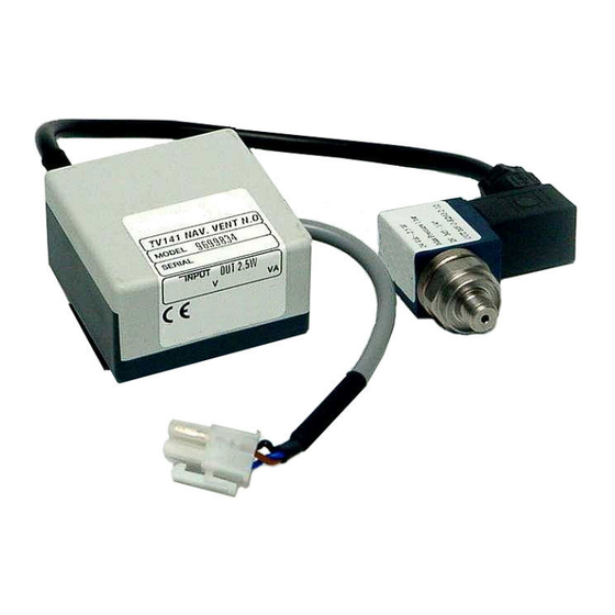
Ventilüberwachungskabel Ausgangssteckverbinder Anschlußkabel Überwachungseinheit/ Pumpenschaltglied Ventilüberwachungseinheit Eingangssteckverbinder Abbildung 2 Bauteile der Baugruppe Beim Zusammenbau der Baugruppe dürfen der Gewindering und die VORSICHT! Befestigungsmutter der Spule im Ventilinneren nicht losgeschraubt werden. TV 141 Navigator Vent Valve User Manual 87-900-911-01 (F) 19/44... - Seite 20 Nach Abschluß der mechanischen Installation, Verbindungskabel vom Ventil zur Überwachungseinheit, sowie Verbindungskabel von der Überwachungseinheit des Elektroventils zum Schaltglied der Pumpe anschließen. Zum Befestigen des Schaltgehäuses, beigefügtes Klettband verwenden. 20/44 TV 141 Navigator Vent Valve User Manual / 87-900-911-01 (F)
-
Seite 21: Entsorgung
Der Endabnehmer sollte daher den Lieferanten des Geräts - d.h. die Muttergesellschaft oder den Wiederverkäufer - kontaktieren, um den Entsorgungsprozess zu starten, nachdem er die Verkaufsbedingungen geprüft hat. TV 141 Navigator Vent Valve User Manual 87-900-911-01 (F) 21/44... - Seite 22 Anleitung zur Installation Entsorgung 22/44 TV 141 Navigator Vent Valve User Manual / 87-900-911-01 (F)
-
Seite 23: Procédure Pour L'installation
TV 141 Navigator Vent Valve User Manual Procédure pour l’installation Généralités Caractéristiques techniques Unité de commande Câbles de connexion Vent valve Installation Mise au Rebut Traduction de la mode d’emploi originale 23/44... -
Seite 24: Généralités
Procédure pour l’installation Généralités Généralités Le kit “TV 141 Navigator Vent Valve” est composé d’une unité de commande et d’une valve qui forment un dispositif complet pour la ventilation automatique de la pompe pendant la phase d’extinction ou en cas de chute de tension. La valve en état de repos (non alimentée) est normalement ouverte. -
Seite 25: Caractéristiques Techniques
Température de service 0 à 40 °C Température de -20 à 50 °C stockage Câbles de connexion Entrée 120 mm (4,72 inch) Sortie de la valve 200 mm (7,87 inch) TV 141 Navigator Vent Valve User Manual 87-900-911-01 (F) 25/44... -
Seite 26: Vent Valve
2,5 W Température de “bakeout” 60 °C Poids 140 g (0,3 lbs) Les dimensions d’encombrement de la valve sont indiquées sur la figure ci-après. Figure 1 Dimensions en mm 26/44 TV 141 Navigator Vent Valve User Manual / 87-900-911-01 (F) -
Seite 27: Installation
Procédure pour l’installation Installation Installation Les éléments composant le kit TV 141 Navigator Vent Valve sont illustrés sur la figure ci-après. Ces éléments sont livrés désassemblés; par conséquent le client devra effectuer l’assemblage du kit. Adaptateur Filtre à air Joint torique torique Câble valve-dispositif... - Seite 28 Pour fixer le boîtier du dispositif de commande utiliser le velcro livré avec le kit. 28/44 TV 141 Navigator Vent Valve User Manual / 87-900-911-01 (F)
-
Seite 29: Mise Au Rebut
Après avoir vérifié les termes et conditions du contrat de vente, l’utilisateur final est donc prié de contacter le fournisseur du dispositif, maison mère ou revendeur, pour mettre en oeuvre le processus de collecte et mise au rebut. TV 141 Navigator Vent Valve User Manual 87-900-911-01 (F) 29/44... - Seite 30 Procédure pour l’installation Installation 30/44 TV 141 Navigator Vent Valve User Manual / 87-900-911-01 (F)
-
Seite 31: Installation Procedure
TV 141 Navigator Vent Valve User Manual Installation procedure Overview Technical Characteristics 33 Control Unit Connection Cables 33 Vent Valve Installation Disposal Original Instructions 31/44... - Seite 32 Installation procedure Overview Overview The “TV 141 Navigator Vent Valve” kit, consisting of a control unit and valve, is a complete unit for automatic pump venting when the pump is switched off or during a power failure. The valve is normally...
-
Seite 33: Technical Characteristics
Delay Approx. 0.8 seconds Operating temperature 0 to 40 °C Storage temperature -20 to 50 °C Connection Cables Input 120 mm (4.72 inches) Output from valve 200 mm (7.87 inches) TV 141 Navigator Vent Valve User Manual 87-900-911-01 (F) 33/44... -
Seite 34: Vent Valve
24 Vdc ± 10% Power 2.5 W Bakeout temperature 60 °C Weight 140 g (0.3 lbs) The following figure shows the valve’s overall dimensions. Figure 1 Dimensions in mm 34/44 TV 141 Navigator Vent Valve User Manual / 87-900-911-01 (F) -
Seite 35: Installation
Valve control unit Input connector Figure 2 Kit Components When assembling the kit be careful not to unscrew the coil securing ring and nut CAUTION! inside the valve. TV 141 Navigator Vent Valve User Manual 87-900-911-01 (F) 35/44... - Seite 36 Use the velcrose provided to secure the controller box. 36/44 TV 141 Navigator Vent Valve User Manual / 87-900-911-01 (F)
-
Seite 37: Disposal
The end user is therefore invited to contact the supplier of the device, whether the Parent Company or a retailer, to initiate the collection and disposal process after checking the contractual terms and conditions of sale. TV 141 Navigator Vent Valve User Manual 87-900-911-01 (F) 37/44... - Seite 38 Installation procedure Disposal 38/44 TV 141 Navigator Vent Valve User Manual / 87-900-911-01 (F)
- Seite 44 Request for Return Form Sales and Service Offices United States India Southeast Asia Agilent Technologies Agilent Technologies India Pvt. Ltd. Agilent Technologies Sales Sdn Bhd Vacuum Products Division Vacuum Product Division Vacuum Products Division 121 Hartwell Avenue G01. Prime corporate Park,...