PEERLESS ST670 Installation Und Montage
Inhaltsverzeichnis
Verfügbare Sprachen
Verfügbare Sprachen
Quicklinks
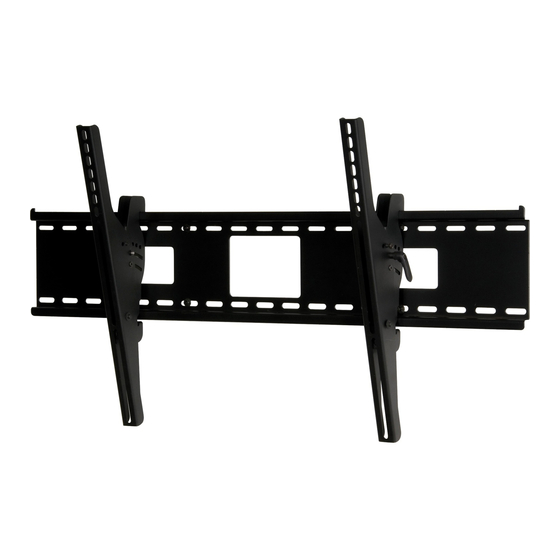
Installation and Assembly:
SmartMount
Flat Panel Screens
Model #
ST670, ST670P, ST670-S, ST670P-S,
SWS520/BK, SWS520/SI
ST680, ST680P, ST680-S, ST680P-S
Features:
• Screen held only 3" (76 mm) from wall for a discreet installation
• Wall plate design allows for wall acces allowing multiple cable management options
• Universal tilt brackets easily hook onto wall plate for fast installation
• Adjustable up to 15° of forward tilt and up to -5° backward tilt for optimal viewing angle
• One-touch tilt for effortless adjustment
• Pre-tensioned universal tilt bracket allows for tilt angle adjustment in one easy motion.
• Easy grip handle locks the screen position into place
• Optional IncreLok feature offers fixed tilts at -5°, 0°, 5°, 10° and 15° increments
• Includes Sorted-For-You™ fastener pack for installation to wood studs, concrete, and cinder block
• Optional horizontal adjustment of up to 8" (203 mm) (depending on screen model) for perfect
screen placement
• Available in Black or Silver
®
Universal Tilt Wall Mount for LCD and Plasma
Screen Size Range
42''- 71'' (107 - 180 cm)
61''- 102'' (155 - 259 cm)
Max. Load Capacity
250 lb (113 kg)
350 lb (159 kg)
ISSUED: 03-25-09 SHEET #: 202-9334-1
U L
C
US
©
Kapitel
Inhaltsverzeichnis

Verwandte Anleitungen für PEERLESS ST670


Inhaltszusammenfassung für PEERLESS ST670
- Seite 10 Anbringung und Zusammenbau: SmartMount®-Universal-Wandkipphalter für LCD- und Plasma- Flachbildschirme Modell-Nr. Bildschirmgröße Max. Tragfähigkeit gem. UL-Zulassung ST670, ST670P, ST670-S, ST670P-S, 42''- 71'' (107 - 180 cm) 250 lb (113 kg) © SWS520/BK, SWS520/SI ST680, ST680P, ST680-S, ST680P-S 61''- 102'' (155 - 259 cm)
-
Seite 11: Für Den Zusammenbau Erforderliche Werkzeuge
HINWEIS: Lesen Sie die gesamte Anleitung, bevor Sie mit der Anbringung und dem Zusammenbau beginnen. ACHTUNG • Beginnen Sie mit der Anbringung Ihres Peerless-Produkts erst, nachdem Sie die in dieser Montageanleitung enthaltenen Anleitungen und Achtungshinweise gelesen und sich gründlich mit ihnen vertraut gemacht haben. Falls Sie Fragen hinsichtlich irgendeiner der Anleitungen oder Achtungshinweise haben, wenden Sie sich in den USA bitte an den Peerless-Kundendienst unter der Rufnummer 1-800-865-2112. -
Seite 12: Teileliste
Bevor Sie beginnen, stellen Sie sicher, dass alle Teile gezeigt werden, die mit Ihrem Produkt. Teileliste SWS520/BK SWS520/SI ST680 ST680-S ST680P ST680P-S ST670 ST670-S ST670P ST670P-S Beschreibung Anz. AA wandplatte 200-1901 200-4901 200-1901 200-4901 200-1902 200-4902 200-1902 200-4902 BB Linke Kipphalterung... -
Seite 13: Befestigungsteile Für Sicherheitsadapterhalterung
Befestigungsteile für Sicherheitsadapterhalterung M4 x 12 mm (6) M5 x 12 mm (4) M6 x 12 mm (4) (510-1079) M8 x 15 mm (6) (520-1064) (520-1050) (520-1068) M4 x 25 mm (4) M5 x 25 mm (4) M6 x 25 mm (4) (510-1082) (520-1122) (520-1211) -
Seite 14: Anbringung An Wand Mit Drei Holzständerreihen
Anbringung an Wand mit drei Holzständerreihen ACHTUNG • Bei der Anbringung muss darauf geachtet werden, dass die Wand die kombinierte Last von Bildschirm und allen Befestigungsteilen und -komponenten tragen kann. • Ziehen Sie die Schrauben fest genug an, dass die Wandplatte sicher befestigt ist, doch ohne sie zu überdrehen. Durch Überdrehen können die Schrauben beschädigt werden, wodurch ihr Haltevermögen stark reduziert wird. -
Seite 15: Anbringung An Massivbeton Oder Porenbetonstein
ACHTUNG • Bei der Anbringung von Peerless-Wandhaltern an Porenbetonstein muss sichergestellt werden, dass die tatsächliche Stärke des Betons, in den das Loch für die Betondübel gebohrt wird, mindestens 35 mm (1 3/8 Zoll) beträgt. Bohren Sie nicht in Mörtelfugen! Achten Sie darauf, dass die Anbringung an einem massiven Teil des Blocks erfolgt, im Allgemeinen mindestens 25 mm (1 Zoll) von der Blockseite entfernt. -
Seite 16: Anbringung Von Kipphalterungen
Befestigung von Kipphalterungen am Bildschirm mit Hilfe des Befestigungsteilesortiments ACHTUNG • Ziehen Sie die Schrauben so an, dass die Adapterhalterungen sicher befestigt sind. Ziehen Sie die Schrauben nicht zu fest an. Durch die beim Überdrehen entstehende Spannung können die Schrauben beschädigt werden, was ihr Haltevermögen stark reduziert und möglicherweise dazu führen kann, dass die Schraubenköpfe sich lösen. - Seite 17 Bildschirme mit flacher Rückseite Die korrekten Befestigungsteile können der Bildschirm-Kompatibilitätstabelle entnommen werden. Eine vollständige Bildschirm-Kompatibilitätsta- belle für diesen Halter ist für Modelle ST670 unter www.peerlessmounts.com/3 bzw. für Modelle ST680 unter www.peerlessmounts.com/4 zu finden. Beginnen Sie mit der längeren Schraube und schrauben Sie diese in der unten abgebildeten Reihenfolge von Hand durch die Mehrlochscheibe, die Adapterhalterung und den Abstandhalter in den Bildschirm.
-
Seite 18: Anbringung Des Flachbildschirms An Der Wandplatte
DETAILANSICHT 2 Addildung. 4.1 18 von 18 AUSGEGEBEN: 03-25-09 BLATT NR.: 2029334-1 © 2009, Peerless Industries, Inc. Alle Rechte vorbehalten. Alle anderen Marken- und Produktnamen sind eingetragene Marken der jeweiligen Eigentümer. Peerless Industries, Inc. 3215 W. North Ave. Melrose Park, IL 60160...