Siemens FDF241-9 Inbetriebsetzung
Vorschau ausblenden
Andere Handbücher für FDF241-9:
- Technisches handbuch (66 Seiten) ,
- Montage (8 Seiten) ,
- Bedienungsanleitung (70 Seiten)
Quicklinks
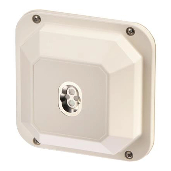
FDF241-9
en
Flame detector
de
Flammenmelder
fr
Détecteur de flammes
es
Detector de llamas
it
Rivelatore di fiamma
en
Commissioning
de
Inbetriebsetzung
fr
Mise en service
es
Puesta en servicio
it
Messa in servizio
en
Commissioning
General information
When delivered, the flame detectors are set for operation
on an FDnet/C-NET detector line.
The automatic switch from FDnet/C-NET operation to
collective operation cannot be made on some collective
control panels. In these cases, you must switch the
detector over manually. The detector always switches
automatically from collective operation to FDnet/C-NET
operation.
Switching over to collective operation
Prerequisite
Use a base that is not connected to the detector line.
A6V10299652_c_--_--
2018-07-25
LINE
+
Fig. 1
Procedure
Note the positive and negative poles.
Connect base to a DC 12...28 V source of voltage, e.g.
1.
a battery, according to connection diagram (Fig. 1).
Insert detector into base for approx. 15 seconds.
2.
The detector is switched over to collective operation
ð
and can be connected to a collective detector line.
For more information, see documents 007011
(Technical manual) and 008121 (Installation).
Building Technologies
Control Products and Systems

Verwandte Anleitungen für Siemens FDF241-9


Inhaltszusammenfassung für Siemens FDF241-9
- Seite 1 FDF241-9 Flame detector Flammenmelder Détecteur de flammes Detector de llamas Rivelatore di fiamma Commissioning Inbetriebsetzung Mise en service LINE Puesta en servicio Messa in servizio Fig. 1 Commissioning Procedure General information Note the positive and negative poles. When delivered, the flame detectors are set for operation on an FDnet/C-NET detector line.
- Seite 2 Inbetriebsetzung Vorgehen Allgemeine Information Beachten Sie die Plus- und Minus-Anschlüsse. Bei der Auslieferung sind die Flammenmelder eingestellt für den Betrieb an einer FDnet/C-NET- Verbinden Sie den Sockel gemäß Anschlussschema Melderlinie. (Fig. 1) mit einer Gleichspannungsquelle von An einigen kollektiven Zentralen ist die automatische DC 12…28 V, z.
- Seite 3 Puesta en servicio Procedimiento Información general Observe los polos positivos y negativos. A la entrega, los detectores de llamas están ajustados para el funcionamiento en una línea de detectores De acuerdo con el diagrama de conexión (Fig. 1), FDnet/C-NET. conecte el zócalo a una fuente de tensión continua de En algunas unidades de control colectivas no puede DC 12…28 V, p.
- Seite 4 Technical data: see doc. 007011 FDF241-9 - Flame detector incl. short-circuit isolator for use in fire detection and fire alarm systems installed in buildings. 305/2011/EU (CPR): EN 54-10 / EN 54-17 ; 2014/30/EU (EMC): EN 50130-4 / EN 61000-6-3 ; 2011/65/EU (RoHS): EN 50581 The declared performance and conformity can be seen in the Declaration of Performance (DoP) and the EU Declaration of Conformity (DoC), which is obtainable via the Customer Support Center: Tel.