Inhaltsverzeichnis
Werbung
Quicklinks
Werbung
Inhaltsverzeichnis

Verwandte Anleitungen für PEERLESS Slimline MOWV241/BK


Inhaltszusammenfassung für PEERLESS Slimline MOWV241/BK
- Seite 1 MOWV241/BK MOWV241/BK ISSUED 10-10-10 REV0...
-
Seite 2: Inhaltsverzeichnis
Inhalt Contenu Contenuti Table of contents Índice Inhoudsopgave Contents ………………………………....… Inhalt ……………………………......…… Important Safety Instructions ….………………… Sicherheitshinweise………………………………… Parts and Accessories …………………………… 6 Teile und Zubehör ………………………….... 6 Required Tools ………………………………………… 7 Benötigte Werkzeuge ……………………………… 7 Installation …………………………………………… 8 Montage……………………………………………… 8 Installation per Model …………....……... -
Seite 3: Important Safety Instructions
Important Safety Instructions Istruzioni di sicurezza Sicherheitshinweise Instructions de sécurité Normas de seguridad Veiligheidsinstructies If you install the product improperly, it may cause severe personal injury or product damage. If you do not understand the installation method, contact a professional installer. Do not install the product if any part or component of the product is damaged or missing. - Seite 4 Important Safety Instructions Si vous installez le produit en utilisant une méthode incorrecte, ceci peut entraîner des blessures graves ou gravement endommager le produit. Si vous ne comprenez pas la méthode d’installation, contactez un installateur professionnel. N’installez pas le produit si certaines parties ou certains composants du produit sont endommagé(e)s ou manquant(e)s. Ce produit a été...
- Seite 5 Important Safety Instructions Si instala el producto siguiendo un método inadecuado, podrían producirse graves daños personales o en el producto. Si no comprende el método de instalación, póngase en contacto con un instalador profesional. No instale el producto si alguna de las piezas o componentes de dicho producto presentan daños o faltan. Este producto se ha diseñado para ser utilizado en una pared vertical construida con hormigón macizo, bloques macizos o ladrillos.
-
Seite 6: Parts And Accessories
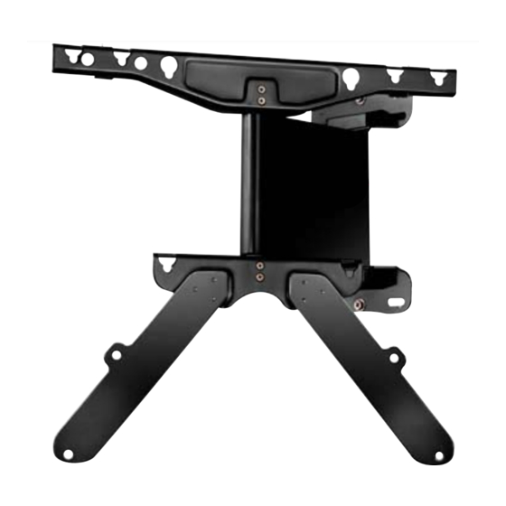
Teile und Zubehör Parties et Accessoires Le parti e gli Accessori Parts and Accessories Parts and Accessories Onderdelen en accessoires SetUP Home Mem1 Mem2 Wall Mount Remote Controller Installation Supplement Manual Wing Plate Wandhalterung Fernbedienung Montage Ergänzung - Anleitung Tragflache Fixation murale Télécommande Installation manuelle supplémentaire... -
Seite 7: Required Tools
Benötigte Werkzeuge Outils nécessaires Attrezzi richiesti Required Tools Herramientas necesarias Benodigd gereedschap Power drill Hammer Screwdriver (+) Bohrmaschine Hammer Schraubenzieher (+) Perceuse Marteau Tournevis (+) Trapano Martello Cacciavite (+) Taladro eléctrico Martillo Destornillador (+) Boormachine Hamer Schroevendraaier (+) Φ9 (3/8˝) Masonry Drill Bit Mauer-Bohrspitze Mèche de percement de la maçonnerie... -
Seite 8: Installation
Montage Installation Installazione Installation Instalación Installatie Leveler (W-D) 90° Attach the separately enclosed installation supplement manual (A-C) on the wall where the product will be installed. Use the leveler (W-D) to ensure the product is horizontal. (Be sure to check the center of the installation supplement manual, because the centers of Automatic Wall Mount and TV are different.) Befestigen Sie die separat beigelte Montage Schablone (A-C) an der Wand, dort wo das Produkt installiert werden soll. - Seite 9 Quick Manual Installation Installation 55mm After attaching the installation supplement manual on the wall, drill 4 holes or, if necessary, 8 holes at required places using the wood drill bit (3Φ/W-C) or concrete drill (9Φ drill bit). Nach der Anbringung der Montage Schablone an der Wand, bohren Sie 4 Löcher oder falls es notwendig ist, 8 Löcher an den benötigen Stellen mit dem Holz-Bohrer (3Φ/W-C) oder mit dem Beton-Bohrer(9Φ...
-
Seite 10: Installation Per Model
Installation per Model Installation Note the VESA standard for the TV and follow proper installation instruction. Beachten Sie bitte die Vesa-Standarts für TV-Geräte und folgen Sie die entsprechenden Montage-Anleitungengen. Notez le standard de VESA pour le TV et suivez l’instruction d’installation appropriée. Notare il VESA standard per la TV e seguire istruzione d’installazione appropriata. - Seite 11 How to assemble 200mm×200mm TV Installation A=20 Leveler (W-D) M6Х50mm After inserting the anchors (W-B) into the drilled holes, tighten the screws (W-A) in the 4 required positions. Ensure to maintain horizontal, when tightening the screws. This step requires more than two persons. The product may fall and cause product damage and/or serious injury. Nach dem Einführen der Düben (W-B) in die Löcher, ziehen Sie die Schrauben (W-A) an den 4 benötigten Stellen an.
- Seite 12 How to assemble 200mm×200mm TV Installation Washer(N-A) A=20 From M-A to M-J When tightening the screws on the TV panel, the corresponding screws must be selected because the size and the length of the screws differ for each TV specification (From M-A to M-J) Insert washers under each screw and tighten the screws at 2 places in the upper area.
- Seite 13 How to assemble 200mm×200mm TV Installation A=20 How to assemble a Round type TV Wie ein Runder TV-Typ installiert wird Comment assembler un TV de type ronde Come assemblare un TV, tipo rotondo Cómo ensamblar el TV tipo esférico Hoe een TV met ronde achterkant te monteren If the screw is too long or short when tightening it on the TV, it may cause safety risks.
- Seite 14 How to assemble 200mm×200mm TV Installation A=20 90° To assemble the TV on the automatic wall mount that is fastened on the wall, you must pull the arm horizontally so that it draws 90 degrees as shown on the picture. (Pull the top two corners as you turn it.) Zur Anbringung des TV- Gerätes an der automatischen Wandhalterung, die an der Wand befestigt ist, sollten Sie den Arm der Vorrichtung in horizontaler Stellung bringen und um 90 Grad drehen, so wie es im Bild gezeigt wird.
- Seite 15 How to assemble 200mm×200mm TV Installation A=20 The screws that have been fastened on the back of the main frame of the TV must be inserted into the bracket found on the automatic wall mount (The inner hole on the VESA 200x200-TV plate). This step may require two people or more.
- Seite 16 How to assemble 200mm×200mm TV Installation A=20 Leveler (W-D) Assemble the TV and the auto wall mount together with 2 screws in the upper area and 2 screws in the lower area, using screwdriver. Use the leveler to check again that it is horizontal. If the automatic wall mount is not horizontally installed, the TV may tilt.
- Seite 17 How to assemble 300mm×300mm TV Installation A=30 M5Х6mm Firmly attach the separately provided wing plates, both left and right, (A-D) onto the automatic wall mount with 3 screws (M-K) on each wing, total of 6 screws, as shown in picture above. Wie auf der Abbildung zu sehen ist, befestigen Sie die separat erworbenen zusätzlichen Tragplatten links und rechts (A-D) an die automatische Wandhalterung mit jeweils 3 Schrauben (M-K) an jeder Platte, insgesamt 6 Schrauben.
- Seite 18 How to assemble 300mm×300mm TV Installation A=30 Leveler (W-D) M6Х50mm After inserting the anchors (W-B) into the drilled holes, tighten the screws (W-A) in the 4 required positions. Ensure to maintain horizontal, when tightening the screws. This step requires more than 2 persons. The product may fall and cause product damage and/or serious injury. Nach dem Einführen der Dübel (W-B) in den Löchern ziehen Sie die Schrauben (W-A) in den 4 erforderlichen Stellen an.
- Seite 19 How to assemble 300mm×300mm TV Installation A=30 Washer(N-A) From M-A to M-J When tightening the screws on the TV panel, the corresponding screws must be selected because the size and the length of the screws differ for each TV specification (From M-A to M-J) Insert washers under each screw and tighten the screws at 2 places in the upper area.
- Seite 20 How to assemble 300mm×300mm TV Installation A=20 How to assemble a Round type TV Wie ein Runder TV-Typ installiert wird Comment assembler un TV de type ronde Come assemblare un TV, tipo rotondo Cómo ensamblar el TV tipo esférico Hoe een TV met ronde achterkant te monteren If the screw is too long or short when tightening it on the TV, it may cause safety risks.
- Seite 21 How to assemble 300mm×300mm TV Installation A=30 90° To assemble the TV on the automatic wall mount that is fastened on the wall, you must pull the arm horizontally so that it draws 90 degrees as shown on the picture. (Pull the top two corners as you turn it.) Zur Anbringung des TV- Geräts an der automatischen Wandhalterung die an der Wand befestigt ist, sollten Sie den Arm der Vorrichtung in horizontaler Stellung bringen und um 90 Grad drehen, so wie es im Bild gezeigt wird.
- Seite 22 How to assemble 300mm×300mm TV Installation A=30 The screws that have been fastened on the back of the main frame of the TV must be inserted into the bracket found on the automatic wall mount (The center hole on the VESA 300x300-TV plate). This step may require two people or more.
- Seite 23 How to assemble 300mm×300mm TV Installation A=30 Firmly tighten the screws at the 2 upper locations. Use the same screws to tighten at the 2 lower locations. Nach dem festen Anziehen der Schrauben an den 2 oberen Stellen, benutzen Sie die gleichen Schrauben um die 2 unteren Stellen anzuziehen, wie im Bild gezeigt.
- Seite 24 How to assemble 300mm×300mm TV Installation A=30 Leveler (W-D) Assemble the TV and the auto wall mount together with 2 screws in the upper area and 2 screws in the lower area, using screwdriver. Use the leveler to check again that it is horizontal. If the automatic wall mount is not horizontally installed, the TV may tilt.
- Seite 25 How to assemble 400mm×400mm TV Installation A=40 M5Х6mm Firmly attach the separately provided wing plates, both left and right, (A-D) onto the automatic wall mount with 3 screws (M-K) on each wing, total of 6 screws, as shown in picture above. Wie auf der Abbildung zu sehen ist, befestigen Sie die separat erworbenen zusätzlichen Tragplatten inks und rechts (A-D), an die automatischen Wandhalterung mit jeweils 3 Schrauben (M-K) an jeder Platte, insgesamt 6 Schrauben.
- Seite 26 How to assemble 400mm×400mm TV Installation A=40 Leveler (W-D) M6Х50mm After inserting the anchors (W-B) into the drilled holes, tighten the screws (W-A) in the 4 required positions. Ensure to maintain horizontal, when tightening the screws. This step requires more than 2 persons. The product may fall and cause product damage and/or serious injury. Nach dem Einführen der Dübel (W-B) in den Löchern ziehen Sie die Schrauben (W-A) in den 4 erforderlichen Stellen an.
- Seite 27 How to assemble 400mm×400mm TV Installation A=40 Washer(N-A) From M-A to M-J When tightening the screws on the TV panel, the corresponding screws must be selected because the size and the length of the screws differ for each TV specification (From M-A to M-J) Insert washers under each screw and tighten the screws at 2 places in the upper area.
- Seite 28 How to assemble 400mm×400mm TV Installation A=40 How to assemble a Round type TV Wie ein Runder TV-Typ installiert wird Comment assembler un TV de type ronde Come assemblare un TV tipo rotondo Cómo ensamblar el TV tipo esférico Hoe een TV met ronde achterkant te monteren If the screw is too long or short when tightening it on the TV, it may cause safety risks.
- Seite 29 How to assemble 400mm×400mm TV Installation A=40 90° To assemble the TV on the automatic wall mount that is fastened on the wall, you must pull the arm horizontally so that it draws 90 degrees as shown on the picture. (Pull the top two corners as you turn it.) Zur Anbringung des TV- Gerätes an der automatischen Wandhalterung, die an der Wand befestigt ist, sollten Sie den Arm der Vorrichtung in horizontaler Stellung bringen und um 90 Grad drehen, so wie es im Bild gezeigt wird.
- Seite 30 How to assemble 400mm×400mm TV Installation A=40 The screws that have been fastened on the back of the main frame of the TV must be inserted into the bracket found on the automatic wall mount (The outer hole on the VESA 400x400-TV plate). This step may require two people or more..
- Seite 31 How to assemble 400mm×400mm TV Installation A=40 Firmly tighten the screws at the 2 upper locations. Use the same screws to tighten at the 2 lower locations. Nach dem festen Anziehen der Schrauben an den 2 oberen Stellen, benutzen Sie die gleichen Schrauben um die 2 unteren Stellen anzuziehen, wie im Bild gezeigt.
- Seite 32 How to assemble 400mm×400mm TV Installation A=40 Leveler (W-D) Assemble the TV and the automatic wall mount together with 2 screws in the upper area and 2 screws in the lower area, using screwdriver. Use the leveler to check again that it is horizontal. If the automatic wall mount is not horizontally installed, the TV may tilt.
- Seite 33 Installation IR Receiver IR-Empfänger Récepteur IR Ricevitore IR Receptor de IR IR-ontvanger SET UP Power Cable(220V) EX LINE Netzkabel(220V) DC 12V Câble d’alimentation (220V) Cavo di alimentazione (220V) Cable de alimentación (220V) Netsnoerkabel (220V) Connect the adapter and the receiver to the terminal as shown in the picture. If the plugs are not completely connected, the device may not operate.
- Seite 34 Installation Remove the plastic cover of the adhesive area which is located on the lower part of the receiver and attach the receiver on the upper part of the TV as shown in the picture. Entfernen Sie die Plastikabdeckung im Klebe-Bereich, welcher sich am Boden des Empfängers befindet und befestigen Sie den Empfänger am oberen Rand des TV-Geräts, wie im Bild gezeigt.
- Seite 35 Installation Power Cable(220V) Netzkabel(220V) Câble d’alimentation (220V) Cavo di alimentazione (220V) SET UP Cable de alimentación (220V) EX LINE Netsnoerkabel (220V) DC 12V EX LINE Connection to TV Anschluß am TV Brancher au téléviseur Connettere alla TV Conectar al TV Op TV aansluiten For Samsung TV, connect the automatic wall mount and the TV with the EX-LINE cable line as shown in the picture.
- Seite 36 Installation If the power line from the main frame of the TV or the connecting lines of other devices comes into contact with the TV or other devices (when the distance between the wall and TV is more than 3 cm), use the spring as shown in the picture.
-
Seite 37: Initial Set-Up
Originaleinstellungen Configuration initiale Configurazione iniziale Initial set-up Configuración inicial Eerste instelling SetUP Home Mem1 Mem1 Mem2 Mem2 The automatic wall mount moves to the wall and finds the initial position, when the setup button is selected as shown in the picture. If the automatic wall mount finds the wall limit, press the Setup button to designate the initial position. -
Seite 38: Wall Limit Right And Leftt
Wandbegrenzung rechts Limite droite du mur Limite parete destra Wall Limit Right Límite derecho de la pared Bereik rechts SetUP SetUP Home Home Mem1 Mem2 Mem1 Mem2 Picture 1 Picture 2 Picture 3 Bild 1 Bild 2 Bild 3 Tableau 1 Tableau 2 Tableau 3 Figura 1... - Seite 39 Wandbegrenzung links Limite gauche du mur Limite parete sinistra Wall Limit Left Límite izquierdo de la pared Bereik links SetUP SetUP Home Home Mem1 Mem2 Mem1 Mem2 Picture 1 Picture 2 Picture 3 Bild 1 Bild 2 Bild 3 Tableau 1 Tableau 2 Tableau 3 Figura 1...
- Seite 40 Designate Left and Right Wall Limit Bestimmung der linken und rechten Wandbegrenzung Déterminer les limites gauche et droite du mûr Designare Sinistra e Destra del Limite del Muro Designar el límite izquierdo y derecho de la pared Het bereik links en rechts aangeven SetUP Home Mem1...
-
Seite 41: Using The Memory(Optional)
Using the Memory(Optional) Verwendung der Speicherfunktion(Optional) Utiliser la mémoire (Facultatif) Uso della memoria (facoltativo) Utilización de la memoria (opcional) Gebruik van het geheugen (naar keuze) A. Memory 1 SetUP Swivel to the desired position by using the direction buttons, press and hold the Mem1 button for 5 seconds until LED turns on to set memory 1. - Seite 42 Using the Memory(Optional) A. Memoria 1 Ruotare la TV nella posizione desiderata usando i tasti direzionali. Tenere premuto il pulsante Mem 1 per 5 secondi. Quando il LED si accende, la memoria 1 è stata impostata. Se si preme il pulsante Mem1, il supporto si muoverà nella posizione salvata in Memoria 1. B.
-
Seite 43: Product Specifications
Produktspezifikationen Caractéristiques du produit Specifiche tecniche Product Specifications Especificaciones del producto Productspecificaties 4 kg Netto 4 kg Peso Weight Lordo 5.5 kg Gross 5.5 kg Operation Angolo Rotazione Tipicamente 20° Swivel Typical 20° angle operativo Max. Load 50kg(110lbs) Carico massimo 50kg(110lbs) Applicable TV Supported VESA... -
Seite 44: Dimensions
Abmessungen Dimensions Dimensioni Dimensions Dimensiones Afmetingen (mm) 55.5 424.1 34.8 MOWV241/BK ISSUED 10-10-10 REV0... - Seite 45 MEMO...
- Seite 46 MEMO...