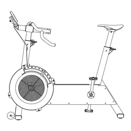
Concept2 BikeErg Montageanleitung
Vorschau ausblenden
Andere Handbücher für BikeErg:
- Zusammenbau, austellung, pflege, wartung und bedienungsanleitung (28 Seiten) ,
- Produktanleitung (16 Seiten) ,
- Bedienungsanleitung
(16) 3/4" (1.9 cm)
PN 1201
with patch
avec frein filet
mit Schraubensicherung
有盖片
(2) 3" (7.62 cm)
PN 1267
(4) 3/4" (1.9 cm)
PN 1248
without patch
sans frein filet
ohne
Schraubensicherung
无盖片
0218
ASSEMBLY INSTRUCTIONS
6-lobe Driver
PN 2230
6 mm L-key
PN 2333
for tightening pedals ONLY
pour serrer la pédale
UNIQUEMENT
NUR zum Festziehen der
Kurbelarmschrauben
仅用于拧紧曲臂紧固件。
Assembly Instructions
EN
BikeErg weight: 58 lb (26 kg)
Space required for use (training area):
48 in x 60 in
(122 cm x 152 cm)
Notice de montage du BikeErg
FR
Poids du BikeErg : 26 kg
Espace nécessaire pour l'utilisation
(zone d'entraînement) :
122 cm x 152 cm
BikeErg Montageanleitung
DE
Gewicht des Gerätes: 26 kg
Maße (bei Benutzung):
122 cm x 152 cm
BikeErg安装说明
中
BikeErg 重量:58 lb (26 kg)
所需使用空间(训练区域):
48 in x 60 in
(122 cm x 152 cm)
Questions? Comments? Problems?
Contact Concept2 directly at
800.245.5676 (U.S. and Canada)
or visit us at concept2.com

Verwandte Anleitungen für Concept2 BikeErg


Inhaltszusammenfassung für Concept2 BikeErg
- Seite 1 ASSEMBLY INSTRUCTIONS Assembly Instructions BikeErg weight: 58 lb (26 kg) Space required for use (training area): 48 in x 60 in (122 cm x 152 cm) Notice de montage du BikeErg Poids du BikeErg : 26 kg Espace nécessaire pour l’utilisation (zone d’entraînement) :...
- Seite 2 BikeErg Assembly Instructions Lay out all parts as shown. 1. Box frame assembly 2. Pedal 3. Rear leg with seat post and saddle 4. Handlebar assembly 5. Front leg with handlebar post 6. Performance Monitor 5 (PM5) 7. Rear foot 8.
- Seite 3 (2) 3/4” (1.9 cm) PN 1201 (2) 3” (7.62 cm) PN 1267 Lay the box frame assembly on the floor and with the flywheel facing down. Route the monitor cable through the notch as shown. Attach the front leg to the box frame assembly using four fasteners.
- Seite 4 BikeErg Assembly Instructions (4) 3/4” (1.9 cm) PN 1201 Orient the box frame assembly with the front leg in its upright position. Attach the front foot with casters using four fasteners. Finger tighten all fasteners first, then tighten each one completely.
- Seite 5 (4) 3/4” (1.9 cm) PN 1201 Attach the rear leg with foot assembly to the box frame using four fasteners (two fasteners per side). Finger tighten only. These fasteners will be tightened fully in step 6. Fixez l’ensemble du bras arrière au cadre en utilisant quatre vis (deux vis par côté).
- Seite 6 BikeErg Assembly Instructions Insert the handlebar assembly into the handlebar post. Positionnez l’ensemble guidon/tige de guidon dans la tige de réglage vertical. Setzen Sie den Lenker-Vorbau in den Vorbauschaft ein. 中 将车把总成 插入车把管内。 Insert the PM5 into the handlebar stem. Do not insert any fasteners until step 10.
- Seite 7 (4) 3/4” (1.9 cm) PN 1248 Note: Be sure to use the four fasteners without patch. Insert two fasteners through the monitor cable tab and into the bottom of the handlebar stem as shown in photo A. Do not tighten screws completely. Insert two fasteners into the top of the handlebar stem as shown in photo B.
- Seite 8 Ziehen Sie beide Feststellknöpfe fest. Weitere Informationen zur Einstellung des Lenkers und Sattels finden Sie in der BikeErg- Gebrauchsanleitung. Dieses Gerät soll auf einer stabilen, ebenen Fläche verwendet werden. Das BikeErg soll ungefähr waagerecht aufgestellt werden. Verwenden Sie die Nivellierschrauben am hinteren Standfuß, um das Gerät auszutarieren.