Herunterladen Inhalt Inhalt Diese Seite drucken
Inhaltsverzeichnis

Werbung

Verfügbare Sprachen
  • DE

Verfügbare Sprachen

  • DEUTSCH, seite 35
'Follow-Up' besturing
'Follow-Up' steering system
'Follow-Up' Steuersystem
Système de pilotage 'Follow-Up'
Mando basculati
Timonerie idrauliche con controllo a
distanza
C o pyrigh t © 2 01 2 Ve t us n .v. Sc h i e da m H o ll a n d
Bedieningshandleiding en
installatieinstructies
Operation manual and
installation instructions
Bedienungshandbuch und
Einbauanleitung
Manuel d'utilisation et
instructions d'installation
Manual de manejo y
instrucciones de instalación
Manuale per l'uso e
istruzioni per l'installazione

Werbung

Inhaltsverzeichnis
loading

Inhaltszusammenfassung für Vetus Follow-Up

  • Seite 1 ‘Follow-Up’ besturing ‘Follow-Up’ steering system ‘Follow-Up’ Steuersystem Système de pilotage ‘Follow-Up’ Mando basculati Timonerie idrauliche con controllo a distanza C o pyrigh t © 2 01 2 Ve t us n .v. Sc h i e da m H o ll a n d...
  • Seite 2 Ce produit répond aux normes de la directive CE- 2004/108/EC (EMC), EN60945 (IEC945) Este producto cumple las normas de la directiva CE 2004/108/EC (EMC), EN60945 (IEC945) Questo prodotto è conforme alle direttive comunitarie 2004/108/EC (EMC), EN60945 (IEC945) 100901.02 Follow-Up Steering System Follow-Up Steering System...
  • Seite 3: Inhaltsverzeichnis

    4.6 Calibratie van de nulstand van het roer ....16 5 Technische gegevens ..........17 6 Storing zoeken ............18 7 Aansluitschema’s ............. 100 8 Hoofdafmetingen ............. 108 Wij bevelen aan om de follow-up bediening door een vakbekwame installateur te laten installeren. Follow-Up Besturing Follow-Up Besturing 100901.02...
  • Seite 4: Bediening

    FUM0004 FUM0005 Drukknop ‘Stand-by’ - In- en uitschakelen van de follow-up besturing - Roercalibratie, samen met de ‘Set’ toets Drukknop ‘Set’ - Wisselen van stuurplaats, overnemen - Instellen roer offset (trimmen) - Roercalibratie, samen met de ‘Stand-by’...
  • Seite 5 Het wijze van bedienen van de minihendel is gelijk aan de wijze van bedienen van de hendel van de vastgemonteerde uitvoering. FUM0026 FUM0027 Drukknop ‘Stand-by’ - In- en uitschakelen van de follow-up besturing 'SET' 'STAND-BY' - Roercalibratie, samen met de ‘Set’ toets Drukknop ‘Set’ - Wisselen van stuurplaats, overnemen - Instellen roer offset (trimmen) - Roercalibratie, samen met de ‘Stand-by’...
  • Seite 6: Inschakelen, Uitschakelen En Keuze Van De Stuurplaats

    Na het inschakelen van de voedingsspanning zal op elke stuur- stand de LED gaan knipperen, elke 1,5 seconde een korte flits. LED flitst elke 1,5 seconden FOLLOW-UP STEERING De follow-up besturing is nu ‘stand-by’. FUM0010 STAND-BY Door op een van de stuurplaatsen één keer op de ‘Stand-by’...
  • Seite 7: Wisselen Van Stuurplaats (Overnemen)

    2.3 Wisselen van stuurplaats (overnemen) Stuurstand 1 (huidige actieve stuurpositie) FOLLOW-UP STEERING Druk op de niet actieve stuurplaats de ‘SET’ toets in. FOLLOW-UP STEERING FUM0006 Stuurstand 2 (passieve stuurpositie) Druk op de SET toets Stuurstand 1 FOLLOW-UP STEERING De LED zal gaan branden. Indien de stand van deze hendel overeenkomt met de stand van de hendel op de andere stuur- plaats zal de LED continue branden.
  • Seite 8: Trimmen Van De Hendels

    Het is mogelijk de hendels tijdens het varen zo te kalibreren dat in de 0-stand van de hendel het schip keurig rechtuit vaart. Instellen trim FOLLOW-UP STEERING Plaats op de actieve stuurstand de hendel in de stand waarbij het schip rechtuit vaart. De hendeluitslag mag maximaal 5°...
  • Seite 9: Gebruik Master-Schakelaar

    Na het inschakelen van een autopiloot zal deze dan ook altijd onmiddellijk de besturing overnemen. Dit ongeacht of de fol- FUM0021 low-up besturing of een non-follow-up besturing al of niet is ingeschakeld. Na het uitschakelen van de autopiloot wordt de besturing weer overgenomen door de voorlaatste bediening.
  • Seite 10: Installatie

    Het is daarom van het grootste belang de in deze handleiding genoemde punten tijdens de installatie volledig op te volgen en te controleren. 3.2 Systeembeschrijving Een follow-up stuursysteem bevat tenminste de volgende hoofdonderdelen: - besturingselectronica (1) - bedieningseenheid, voor...
  • Seite 11: Bedieningseenheid

    3.4 Bedieningseenheid 3.5 Voedingsspanning, hoofdstroomkabels De follow-up stuurinrichting kan zowel op een 12 Volt als op een Bedieningseenheid voor vast montage 24 Volt boordnet worden aangesloten. Voor aansluitschema zie 7.2. Neem in de ‘+’ kabel een hoofd- schakelaar en een zekering (20 A) op.
  • Seite 12: Stuurmachine (Of Aandrijfeenheid)

    3.6 Stuurmachine (of aandrijfeenheid) Aansluiten stuurmachine Raadpleeg het schema, zie 7.2, voor het aansluiten van de De follow-up besturing kan met een van de volgende soorten stuurmachine. stuurmachines samenwerken: - electro-hydraulische pomp met omkeerbare motor Bij omkeerbare motoren* loopte de motorstroom door de aan-...
  • Seite 13: Autopiloot

    (X1) in de positie ‘REV’ staan. Steker losnemen en 180° draaien. Aansluitingen De roerstandgever moet op de besturingskast van de follow-up besturing worden aangesloten zoals in het aansluitschema is Groen aangegeven, zie 7.4.
  • Seite 14: Blokkeerschakelaar (Master)

    Zorg dat het roer in de mid- Monteer in de directe nabijheid van de non-follow-up schake- denstand staat! laar een aan/uit schakelaar. Sluit de aan/uit schakelaar aan zoals in schema 7.7 is aange- geven.
  • Seite 15: Invoeren Maximale Roeruitslag

    J5 J4 J3 J2 kast: FUM0036 Beide maximale roeruitslagen zijn nu in het geheugen inge- - een (1) korte pieptoon voerd en zullen bewaard blijven, ook als de follow-up besturing ‘Vertraging ingeschakeld’. wordt uitgeschakeld. Druk op de toets - twee (2) korte pieptonen...
  • Seite 16: Calibratie Van De Nulstand Van De Hendels

    Een afwijking van de nulstand van het roer, van minder dan 10 Zet alle hendels in de midden- graden, kan tijdens het varen als volgt worden ingesteld: stand (neutraalstand), scha- FOLLOW-UP STEERING kel de voedingsspanning uit Maak bedieningseenheid nummer 1 (de hendel welke is aange- FOLLOW-UP STEERING indien deze ingeschakeld is.
  • Seite 17: Technische Gegevens

    - Bedieningshendels : max. 3 - Blokkeerschakelaar voor master stuurstand - Autopiloot - Non-follow-up schakelaar (joy-stick) - Aan/uit schakelaar voor non-follow-up schakelaar - Roerstandgever : 5 Volt voedingsspanning Signaal : 2,5 Volt -/+ 0,342 V, voor +/- 45° roeruitslag - Omkeerbare motor of magneetkleppen : max.
  • Seite 18: Storing Zoeken

    Er is geen electrische verbinding met de Sluit de roerstandgever correct aan. roerstandgever. 100901.02 Follow-Up Besturing Follow-Up Besturing...
  • Seite 19: Introduction

    4.6 Calibration of zero position of rudder ....32 5 Technical details ............33 6 Fault finding ..............34 7 Wiring diagrams ............100 8 Overall dimensions ..........108 We recommend that the Follow-Up system be installed by a qualified engineer. Follow-Up Steering System Follow-Up Steering System 100901.02...
  • Seite 20: Operating

    FUM0004 FUM0005 Push button ‘Stand-by’ - Switching the Follow-Up steering on and off - Rudder calibration, together with the ‘Set’ button Push button ‘Set’ - Changing steering position, taking over - Setting rudder trimming - Rudder calibration, together with the ‘Stand-by’...
  • Seite 21 The mini handle is operated in exactly the same way as the permanently mounted handle. FUM0026 FUM0027 Push button ‘Stand-by’ - Switching the Follow-Up steering on and off - Rudder calibration, together with the ‘Set’ button 'SET' 'STAND-BY' Push button ‘Set’...
  • Seite 22: Switching On And Off And Choice Of Steering Position

    2.2 Switching on and off and choice of steering position After switching on the power the LED at each steering position will begin to flash every 1.5 seconds. The Follow-Up steering LED flashes every 1.5 seconds FOLLOW-UP STEERING system is now on ‘stand-by’.
  • Seite 23: Changing Steering Position (Taking Over)

    If a master switch is fitted and this has been switched on FUM2009 then a takeover procedure is not possible. Operation is then Steering position 2 only possible from handle 1. (new active steering position) Press the SET button again Follow-Up Steering System Follow-Up Steering System 100901.02...
  • Seite 24: Trimming The Handles

    Press the SET button Changing steering position (taking over) and trim When the controls are taken over at another steering position the trim which has been set remains in force. 100901.02 Follow-Up Steering System Follow-Up Steering System...
  • Seite 25: Use Of Master Switch

    When the autopilot is switched off the previous operating sys- tem will take over. In the case of the Follow-Up system this is the last active handle. 2.7 Use of non-Follow-Up controls (Joystick) In order to use a Joystick the power to the Follow-Up steer-...
  • Seite 26: Installation

    It is therefore essential during the installation to follow and check the points given in this manual completely. 3.2 Description of system A Follow-Up steering system consists of at least the following main parts: - Electronic control unit (1) - operating unit, for permanent installation at the (main)
  • Seite 27: Operating Unit

    3.4 Operating unit Power supply, main cables The Follow-Up steering system can be connected to both a 12 Operating unit for permanent installation Volt or a 24 volt on board power supply. See wiring diagram 7.2. Fit a main switch and a fuse (20 A) in the '+' cable.
  • Seite 28: Steering Drive Unit

    Connecting the steering drive unit See diagram 7.2 for the connections to the steering drive unit. The Follow-Up steering system can work with one of the follow- ing sorts of steering drive units: The current for a reversible motor * runs from the connecting...
  • Seite 29 'REV'. This is done by pulling out the plug and rotating it through 180°. Connections The rudder feedback unit must be connected to the Follow-Up steering system control unit as shown in diagram 7.4. Groen The rudder feedback unit is supplied with 2-core cable, length Green Grün...
  • Seite 30: Blocking Switch (Master)

    If a buzzer taking more current than this is used a relay must be fitted. 4.1 Setting neutral position of rudder feed- back unit Switch on the power. The Follow-Up system must be on 'Stand- 3.10 Non-Follow-Up switch (Joystick) by'! Fit a non-Follow-Up switch (Joystick) at a spot where the user Therefore do not activate any handles or switch on autopilot can easily operate the handle to steer the ship.
  • Seite 31: Setting Maximum Rudder Deflection

    This can be set to a different value in the following way: - Press the ‘Stand-by’ button on one of the operating handles. Switch on the power. The Follow-Up system must be on 'Stand- - Operate the handle and check which way the rudder turns.
  • Seite 32: Calibration Of Zero Position Of Handles

    The boat will now begin to turn because the rudder position is now aligned to that of the handle. If the deviation in the rudder zero position is more than 10 degrees the rudder feedback unit must be set first, see 4.1. 100901.02 Follow-Up Steering System Follow-Up Steering System...
  • Seite 33: Technical Details

    : max. 3 - Blocking switch for master steering position - Autopilot - Non-Follow-Up switch (joystick) - On/off switch for non-Follow-Up switch - Rudder feedback unit : 5 Volt power supply Signal : 2.5 Volt -/+ 0.342 V, for +/- 45º rudder angle - Reversible motor or solenoid valves : max.
  • Seite 34: Fault Finding

    There is no electrical connection to the Connect the rudder position indicator rudder feedback unit. correctly. 100901.02 Follow-Up Steering System Follow-Up Steering System...
  • Seite 35: Einleitung

    4.6 Kalibrierung des Nullstands des Ruders ..... 48 5 Technische Daten ............49 6 Fehlersuche ..............50 7 Schaltpläne ..............100 8 Hauptabmessungen ..........108 Wir empfehlen, die Follow-up-Bedienung von einem fachkundigen Installateur ein- bauen zu lassen. Follow-Up Steuersystem Follow-Up Steuersystem 100901.02...
  • Seite 36: Bedienung

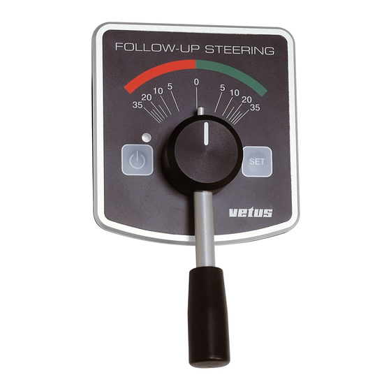
    Steuermaschine bedient, die das Ruder in die ent- FUM0004 FUM0005 sprechende Stellung bringt. Druckknopf ‘Standby’ - Ein- und Ausschalten der Follow-up-Steuerung - Ruderkalibrierung, zusammen mit der ‚Set’-Taste Druckknopf ‘Set’ - Wechseln des Steuerplatzes, Übernehmen - Einstellen Ruder Offset (Trimmen) - Ruderkalibrierung, zusammen mit der ‘Standby’-Taste...
  • Seite 37: Anschließen

    Minihebels entspricht Bedienungsweise des Hebels bei der fest montierten Ausführung. FUM0026 FUM0027 Druckknopf ‘Standby’ - Ein- und Ausschalten der Follow-up-Steuerung 'SET' 'STAND-BY' - Ruderkalibrierung, zusammen mit der ‘Set’-Taste Druckknopf ‘Set’ - Wechseln des Steuerplatzes, Übernehmen - Einstellen Ruder Offset (Trimmen) - Ruderkalibrierung, zusammen mit der ‘Standby’-Taste...
  • Seite 38: Ein- Und Ausschalten Sowie Wahl Des Steuerplatzes

    Steuerplatzes Nach dem Einschalten der Versorgungsspannung muss an jedem Steuerstand die LED-Anzeige aufblinken, und zwar alle LED-Anzeige blinkt FOLLOW-UP STEERING 1,5 Sekunden mit einem kurzen Aufleuchten. Die Follow-up- alle 1,5 Sekunden Steuerung befindet sich jetzt im ‘Standby’. FUM3010 STAND-BY Indem man an einem der Steuerplätze ein Mal auf den FOLLOW-UP STEERING ‘Standby’-Schalter...
  • Seite 39: Wechseln Des Steuerplatzes (Übernehmen)

    2.3 Wechseln des Steuerplatzes Steuerstand 1 (aktuell aktive Steuerposition) FOLLOW-UP STEERING (Übernehmen) Am nicht-aktiven Steuerplatz die ‘SET’-Taste drücken. FOLLOW-UP STEERING FUM3006 Steuerstand 2 (passive Steuerposition) Auf die SET-Taste drücken Steuerstand 1 Die LED-Anzeige leuchtet auf. Falls die Stellung dieses Hebels FOLLOW-UP STEERING mit dem Stand des Hebels auf dem anderen Steuerstand über-...
  • Seite 40: Trimmen Der Hebel

    Es ist möglich, die Hebel während der Fahrt so zu kalibrieren, dass in der 0-Stellung des Hebels das Schiff tadellos gerade- aus fährt. FOLLOW-UP STEERING Einstellung Trimmung Stellen Sie am aktiven Steuerstand den Hebel in die Stellung, in der das Schiff geradeaus fährt.
  • Seite 41: Benutzung Master-Schalter

    Nach dem Einschalten einer Nicht-Follow-up-Bedienung wird diese sofort die Steuerung übernehmen, es sei denn ein Autopilot ist eingeschaltet. Nach dem Ausschalten der Nicht-Follow-up-Bedienung wird die Steuerung wieder vom zuletzt aktiven Hebel der Follow-up- Bedienung übernommen. Follow-Up Steuersystem Follow-Up Steuersystem 100901.02...
  • Seite 42: Installation

    Der Kasten mit der Steuerungselektronik bildet den zentralen Punkt der Installation. 3.1 Einleitung Fast alle anderen Bestandteile des Steuersystems sind hieran Für die Zuverlässigkeit der Follow-up-Steuerbedienung ist die angeschlossen. Qualität des Einbaus maßgeblich. Darum ist es von größter Bedeutung, die in dieser Anleitung genannten Punkte während der Installation vollständig zu befol-...
  • Seite 43: Bedienungseinheit

    3.4 Bedienungseinheit 3.5 Versorgungsspannung, Hauptstromkabel Die Follow-up-Steuereinrichtung lässt sich sowohl an ein 12 Bedienungseinheit zur festen Montage Volt- als auch an ein 24 Volt-Bordnetz anschließen. Für den Schaltplan siehe 7.2 Nehmen Sie in das ‚+’-Kabel einen Hauptschalter und eine FOLLOW-UP STEERING Sicherung (20 A) auf.
  • Seite 44: Steuermaschine (Oder Antriebseinheit)

    3.6 Steuermaschine (oder Antriebseinheit) Anschließen Steuermaschine Ziehen Sie für den Anschluss der Steuermaschine den Die Follow-up-Steuerung kann mit einer der folgenden Arten Schaltplan zu Rate, siehe 7.2. von Steuermaschinen zusammenarbeiten: - elektrohydraulische Pumpe mit Umkehrmotor Bei Umkehrmotoren* läuft der Motorstrom durch die - elektrohydraulische Pumpe mit ständig drehendem Motor (in...
  • Seite 45: Art Der Aufstellung

    Stecker (X1) in der Stellung ‘REV’ stehen. Stecker lösen und um 180° drehen. Anschlüsse Der Ruderstandsgeber muss auf dem Steuerungskasten der Follow-up-Steuerung so angeschlossen werden, wie im Schaltplan angegeben, siehe 7.4. Groen Green Der Ruderstandsgeber ist mit einem 2-adrigen und ca. 2,5 m Grün...
  • Seite 46: Blockierschalter (Master)

    Benutzer den Hebel bequem bedienen kann, um das Achten Sie darauf, dass das Schiff zu steuern. Ruder in Mittelstellung steht! In der direkten Nähe des Nicht-Follow-up-Schalters einen Ein- /Aus-Schalter montieren. Stellschraube am Den Ein-/Aus-Schalter so anschließen, wie in Schaltplan 7.7 Ruderstandsgeber losdrehen.
  • Seite 47: Eingabe Maximaler Ruderausschlag

    J5 J4 J3 J2 Beide maximale Ruderausschläge sind nun in den Speicher Schalters (2) auf dem FUM0036 eingegeben und bleiben erhalten, auch wenn die Follow-up- Steuerungskasten: Steuerung ausgeschaltet wird. - ein (1) kurzer Piepton Halten Sie den Helmstock allzeit frei von mechanischen ’Verzögerung...
  • Seite 48: Kalibrierung Des Nullstands Der Hebel

    4.6 Kalibrierung des Nullstands des Alle Hebel in Mittelstellung Ruders (Nullstand) stellen, FOLLOW-UP STEERING Eine Abweichung des Nullstands des Ruders von weniger als FOLLOW-UP STEERING Versorgungsspannung aus- 10 Grad lässt sich während der Fahrt wie folgt einstellen: schalten, falls diese einge- schaltet sein sollte.
  • Seite 49: Technische Daten

    Steuerungskasten Anschlüsse für: Bedienungshebel : max. 3 Blockierschalter für Master-Steuerstand Autopilot Nicht-Follow-up-Schalter (Joystick) Ein-/Aus-Schalter für Nicht-Follow-up-Schalter Ruderstandsgeber : 5 Volt Versorgungsspannung Signal : 2,5 Volt -/+ 0,342 V, bei +/- 45º Ruderausschlag Umkehrmotor oder Magnetventile : max. Strom 20 A Kurzschlussventil / Kupplung : max.
  • Seite 50: Fehlersuche

    Piepton hören. lang die Stellung nicht geändert, wäh- SET-Taste und Steuermaschine und rend die Steuermaschine dagegen von Ruderstandsgeber überprüfen. der Besteuerungselektronik angesteuert worden ist. Es besteht keine elektrische Verbindung Ruderstandsgeber korrekt anschließen. mit dem Ruderstandsgeber. 100901.02 Follow-Up Steuersystem Follow-Up Steuersystem...
  • Seite 51: Introduction

    5 Spécifications techniques ........65 6 Recherche de pannes ..........66 7 Schémas de raccordement ........100 8 Dimensions principales .......... 108 Nous recommandons de faire installer le système de pilotage follow-up par un installateur agréé. Système de pilotage ‘Follow-Up’ Système de pilotage ‘Follow-Up’...
  • Seite 52: Commande

    Led clignote. Levier passif Un interrupteur externe (dénommé « Master ») vous permet de bloquer tout changement vers un emplacement de pilotage autre que l’emplacement principal. (voir chapitre 2.5) 100901.02 Système de pilotage ‘Follow-Up’ Système de pilotage ‘Follow-Up’...
  • Seite 53 à l’électronique de commande ! La fiche du levier non lié à un emplacement spéci- fique doit donc être introduite dans la prise avant de brancher la tension d’alimentation. Système de pilotage ‘Follow-Up’ Système de pilotage ‘Follow-Up’ 100901.02...
  • Seite 54: Branchement, Débranchement Et Choix De L'emplacement De Pilotage

    Après le branchement de la tension d’alimentation, la LED de chaque emplacement de pilotage se met à clignoter toutes les LED clignotant toutes FOLLOW-UP STEERING 1,5 secondes. Le système de pilotage follow-up est maintenant les 1,5 secondes « stand-by ». FUM4010...
  • Seite 55: Changement D'emplacement De Pilotage (Reprise)

    La commande n’est possible que depuis le levier 1. Emplacement de pilotage 2 (nouvelle position de pilotage active) Appuyer encore une fois sur la touche SET Système de pilotage ‘Follow-Up’ Système de pilotage ‘Follow-Up’ 100901.02...
  • Seite 56: Equilibrage Des Leviers

    Appuyer sur la touche SET Changement d’emplacement de pilotage (Reprise) et équilibrage Lors de la reprise de la commande vers un autre emplacement de pilotage, le déplacement fixé est conservé. 100901.02 Système de pilotage ‘Follow-Up’ Système de pilotage ‘Follow-Up’...
  • Seite 57: Utilisation De L'interrupteur Master

    Après le débranchement du pilote automatique, la commande est reprise par l’avant-dernière commande. Dans le système de pilotage follow-up, il s’agit du dernier levier actif. 2.7 Utilisation d’un système de pilotage Non-follow-up (manche à balai) La tension d’alimentation du système de pilotage follow-up doit être branchée pour pouvoir utiliser le manche à...
  • Seite 58: Installation

    3.2 Description du système Un système de pilotage follow-up comporte dans tous les cas les pièces suivantes : - électronique de commande (1) - unité de commande, pour montage fixe près de l’emplace-...
  • Seite 59: Unité De Commande

    3.5 Tension d’alimentation, câbles de cou- Unité de commande pour montage fixe rant principal Le système de pilotage follow-up peut être raccordé sur un réseau de bord de 12 ou de 24 volts. Pour le schéma de raccordement, voir 7.2.
  • Seite 60: Dispositif De Pilotage (Ou D'entraînement)

    Consulter à cet effet la fiche technique remise par le fournisseur être acheté séparément. de la direction hydraulique. Si un indicateur de position de gouvernail Vetus a déjà été ins- Diviser la capacité du cylindre par le temps bord-bord souhaité tallé, pour un pilote automatique ou des instruments de lecture, pour déterminer la capacité...
  • Seite 61 Ne jamais installer l’indicateur de position du gouvernail à l’extérieur ! L’armoire de commande sur le système de pilotage follow-up Installer l’indicateur de position de gouvernail de telle sorte que comporte des raccordements pour le signal de position de gou- le bras de l’indicateur suive exactement la barre de gouvernail.
  • Seite 62: Interrupteur De Blocage (Master)

    être raccordée à une sortie du pilote Il est possible pendant la navigation d’effectuer séparément un réglage plus précis pour le système de pilotage follow-up, un automatique qui devient positive (+ 12 volts ou + 24 pilote automatique et les instruments de lecture de position de volts) lorsque le pilote automatique est en mode AUTO gouvernail.
  • Seite 63: Déplacement Maximal De Gouvernail

    J5 J4 J3 J2 cette position. et le maintenir enfoncé pen- FUM0032 Le système de pilotage follow-up ralentit le dispositif de pilo- dant environ 3 secondes jus- tage par une suite de connexions et déconnexions rapides du qu’à ce que le vibreur dans moteur réversible (PWM).
  • Seite 64: Calibrage De La Position Zéro Des Leviers

    En cas de déviation de la position zéro du gouvernail de plus de 10 degrés, l’indicateur de position de gouvernail doit être ajusté, voir 4.1. 100901.02 10.0901 Système de pilotage ‘Follow-Up’ Système de pilotage ‘Follow-Up’...
  • Seite 65: Spécifications Techniques

    - Leviers de commande : max. 3 - Interrupteur de blocage pour emplacement de pilotage master - Pilote automatique - Interrupteur Non-follow-up (manche à balai) - Interrupteur marche/arrêt pour interrupteur non-follow-up - Indicateur de position de gouvernail : 5 volts tension d’alimentation...
  • Seite 66: Recherche De Pannes

    était activé par l’électronique de commande. Il n’y a pas de connexion avec l’indica- Raccorder correctement l’indicateur de teur de position de gouvernail. position de gouvernail. 100901.02 Système de pilotage ‘Follow-Up’ Système de pilotage ‘Follow-Up’...
  • Seite 67: Introducción

    Este manual contiene información sobre la instalación y el manejo del sistema de dirección de seguimiento “Follow- 2 Manejo ................. 68 Up” de Vetus. Primero léanse atentamente estas instruccio- 2.1 En general............. 68 nes antes de instalar el sistema de dirección de seguimien- 2.2 Activar, desactivar y selección del...
  • Seite 68: Manejo

    En las instrucciones de manejo del sistema de mando se parte de la base que la instalación se ha ejecutado completamente y FOLLOW-UP STEERING que la puesta en funcionamiento ya ha tenido lugar. Quedan a su disposición los siguientes elementos de manejo: Palanca Con la posición de la palanca se determina la posición del...
  • Seite 69 Unidad de manejo no sujeta a determinado lugar Al hacer uso de la unidad de manejo no sujeta a determinado lugar se pueden realizar las mismas operaciones como con la unidad de manejo instalada fijamente en la posición de gobierno. PALANCA FUM5025 Conectar...
  • Seite 70: Activar, Desactivar Y Selección Del Puesto De Mando

    Una vez activada la tensión de alimentación empezará a des- tellar en cada posición de gobierno el LED, emitirá un breve LED destella cada FOLLOW-UP STEERING flechazo cada 1,5 segundo. El sistema de dirección de segui- 1,5 segundos miento ahora está ‘en posición de espera’.
  • Seite 71: Cambio De Puesto De Mando (Pasar A Otro)

    2.3 Cambio de puesto de mando (pasar Posición de gobierno 1 (posición de gobierno activo actual) FOLLOW-UP STEERING de uno a otro) En el puesto de mando no activo, pulse la tecla ‘SET’. FOLLOW-UP STEERING FUM5006 Posición de gobierno 2 (posición de gobierno pasivo)
  • Seite 72: Calibrar Las Palancas

    Es posible calibrar las palancas durante la navegación de forma tal que en la posición 0 de la palanca la navegación seguirá un rumbo perfectamente hacia delante. FOLLOW-UP STEERING Ajustar la desviación En la posición de gobierno activa ponga la palanca en la posi- ción en la que la navegación siga un rumbo todo recto.
  • Seite 73: Uso Del Interruptor Principal

    2.5 Uso del interruptor principal PALANCA 3 PALANCA 2 Después de activar el interruptor principal, si instalado, sólo se FOLLOW-UP STEERING puede gobernar con la palanca principal (palanca1). Palanca 1 es la palanca que está conectada en la toma J6. INTERRUPTOR...
  • Seite 74: Instalación

    - fuente de energía (5) Ubicación Elija un lugar seco a amplia distancia de una fuente de calor. Las temperaturas altas pueden afectar negativamente el funcio- FOLLOW-UP STEERING namiento del aparato. ¡La electrónica de gobierno nunca puede quedar J5 J4 J3 J2...
  • Seite 75: Unidad De Manejo

    El sistema de dirección de seguimiento se puede conectar tanto en una red de a bordo de 12 Voltios como de 24 Voltios. Para el esquema de conexión véase 7.2. FOLLOW-UP STEERING Incluya en el cable positivo ‘+’ un interruptor principal y un fusible (20 A).
  • Seite 76: Máquina De Dirección (O Unidad De Propulsión)

    BEH con motor de funcionamiento continuo y timón (Vetus art. RFU1718). válvulas magnéticas). Si ya está instalada una unidad de reacción del timón Vetus, Determine el contenido del cilindro que ya está instalado o que para un piloto automático o para instrumentos de lectura, es se va a instalar.
  • Seite 77: Modo De Instalación

    Monte la unidad de reacción del timón de forma tal que timón para un piloto automático Vetus y para los indicadores el brazo del indicador se mueva en el mismo plano que la de posición del timón Vetus.
  • Seite 78: Interruptor De Bloqueo (Principal)

    Para la dirección de seguimiento, véase 4.5. Al aplicar un Piloto automático Vetus también la señal para la Consulte las instrucciones correspondientes para el ajuste posición del timón se conecta en el piloto automático a través preciso de un piloto automático e instrumentos de lectura de la...
  • Seite 79: Introducir La Orientación Máxima Del Timón

    Desactive la tensión de alimentación, si se mueve el timón Mueva el timón con el mando manual a la posición a estri- bor deseada máxima. FOLLOW-UP STEERING FOLLOW-UP STEERING Presione y mantenga presio- nado durante unos 3 segun- FUM0034...
  • Seite 80: Calibración De La Posición Cero De Las Palancas

    Ponga todas las palancas en Una desviación de la posición cero del timón, inferior a 10 gra- la posición media (posición dos, se puede ajustar durante la navegación como sigue: FOLLOW-UP STEERING FOLLOW-UP STEERING neutra), desactive la tensión de alimentación si estuviera Haga de la unidad de manejo número 1 (la palanca que está...
  • Seite 81: Especificaciones Técnicas

    Especificaciones técnicas General Tensión de alimentación : 12 / 24 Voltios corriente continua Corriente absorbida en posición de espera : 150 mA Caja de mandos Conexiones para: - Palancas de control : max. 3 - Interruptor de bloqueo para la posición de gobierno principal - Piloto automático - Interruptor de no-seguimiento (palanca de control orientable) - Interruptor de activación/desactivación para interruptor...
  • Seite 82: Identificación Y Solución De Defectos

    Identificación de defectos Problema Posible Causa Solución En una de las posiciones más extremas La unidad de reacción del timón mide Ajuste correctamente la unidad de reac- se desactiva la máquina de dirección (ya una posición de timón mayor a 45 gra- ción del timón.
  • Seite 83: Introduzione

    Le presenti istruzioni contengono informazioni circa l’in- 1 Introduzione ............... 83 stallazione e l’uso della timoneria idraulica con controllo a distanza Vetus. Leggete attentamente le istruzioni prima di 2 Uso ................84 installare e mettere in funzione la timoneria idraulica con 2.1 Generale ..............
  • Seite 84: Uso

    Le istruzioni per l’uso del sistema di governo partono dal pre- supposto che l’installazione e la messa in funzione siano state correttamente effettuate. FOLLOW-UP STEERING Il sistema è dotato dei seguenti elementi di comando: Leva La posizione della leva determina la posizione del timone.
  • Seite 85 Unità di comando mobili Con le unità di comando mobili possono essere effettuate le stesse operazioni che vengono effettuate con le unità di comando montate fisse in postazione di comando. HANDLE FUM2025 Allacciamento Inserite la spina nella presa di alimentazione e boccate la spina ruotando l’apposito anello un quarto di giro a destra.
  • Seite 86: Accensione, Spegnimento E Scelta Della Postazione Di Comando

    Una volta alimentato il sistema, il LED di ciascuna postazione di comando comincia a lampeggiare con un’intermittenza di 1,5 LED a intermittenza FOLLOW-UP STEERING secondi. Il controllo a distanza si trova ora in ‘stand by’. ogni 1,5 secondi FUM6010 STAND-BY Premendo una volta sul pulsante ‘Stand by’...
  • Seite 87: Cambio Di Postazione Di Comando (Passaggio Di Comando)

    2.3 Cambio di postazione di comando Postazione di comando 1 (postazione di comando FOLLOW-UP STEERING (passaggio di comando) attualmente attiva) Premere il pulsante ‘SET’ della postazione di comando non attiva. FOLLOW-UP STEERING FUM6006 Postazione di comando 2 Premere il (postazione di comando passiva)
  • Seite 88: Regolazione Delle Leve

    Le leve possono essere calibrate in modo tale che l’imbarcazio- ne proceda perfettamente dritta quando la leva di comando si trova nella sua posizione neutra (0). FOLLOW-UP STEERING Impostazione dell’assetto Nella postazione di comando attiva, mettere la leva nella posi- zione in cui l’imbarcazione procede diritta.
  • Seite 89: Uso Dell'interruttore Master

    2.5 Uso dell’interruttore master LEVA 3 LEVA 2 Una volta premuto l’interruttore master, se installato, l’imbar- FOLLOW-UP STEERING cazione può essere governata solo mediante la leva master (leva 1). INTERRUTTORE La leva 1 è la leva collegata all’ingresso J6. MASTER...
  • Seite 90: Installazione

    Scegliete una posizione asciutta e sufficientemente distante da - batteria (5) eventuali fonti di calore. Temperature elevate possono influire negativamente sul funzionamento del dispositivo. FOLLOW-UP STEERING Il microprocessore non deve mai venire a contatto con l’acqua di sentina! J5 J4 J3 J2...
  • Seite 91: Unità Di Comando

    La timoneria idraulica con controllo a distanza può essere col- legata a tensioni di bordo a 12V e a 24V. Per i collegamenti si rimanda allo schema 7.2. FOLLOW-UP STEERING Dotate il cavo ‘+’ di un interruttore principale ed una resistenza (20 A).
  • Seite 92: Macchina Del Timone (O Trasmissione)

    Qualora fosse già installato un trasmettitore della posizione Dividete il volume del cilindro per la durata desiderata della del timone Vetus, per un pilota automatico o per gli strumenti corsa per determinare la portata della EHP da scegliere. di lettura, esso deve essere collegato secondo le indicazioni riportate nel presente manuale.
  • Seite 93: Pilota Automatico

    Installate il trasmettitore della posizione del timone in modo tale segnalatore di posizione del timone, per un pilota automatico che il braccio dell’indicatore segua accuratamente la barra del Vetus e per gli indicatori dell’angolo di barra Vetus. timone. Non collegate mai direttamente un pilota automati- Montate il trasmettitore della posizione del timone in modo co o gli indicatori dell’angolo di barra sul trasmetti-...
  • Seite 94: Interruttore Di Bloccaggio (Master)

    Durante la navigazione è possibile effettuare una regolazione fine della timoneria idraulica con controllo a distanza, del pilota In caso di installazione di un pilota automatico Vetus, anche il automatico e degli strumenti di indicazione dell’angolo di barra, segnalatore di posizione del timone viene collegato al pilota indipendentemente gli uni dagli altri.
  • Seite 95: Impostazione Dell'angolo Massimo Del Timone

    Dare corrente all’impianto. Il comando a distanza deve trovarsi timone. in ‘stand by’! Pertanto, non attivate nessuna leva e mettete il pilota automatico in modo auto. FOLLOW-UP STEERING FOLLOW-UP STEERING Muovete il timone con il comando manuale, fino a raggiungere l’angolo mas-...
  • Seite 96: Calibrazione Della Posizione Neutra Delle Leve

    4.6 Calibrazione della posizione neutra del delle leve timone Posizionate tutte le leve nella Una deviazione dalla posizione neutra del timone, inferiore a 10 FOLLOW-UP STEERING posizione mediana (posizione gradi, può essere regolata durante la navigazione, procedendo FOLLOW-UP STEERING neutra) e togliete l’alimenta- come segue: zione, se inserita.
  • Seite 97: Dati Tecnici

    Dati tecnici Generale Tensione di alimentazione : 12 / 24 Volt CC Corrente assorbita in stand by : 150 mA Pannello del microprocessore Collegamenti per: - Leve di comando : max. 3 - Interruttore di bloccaggio per postazione master - Pilota automatico - Interruttore del comando a Joy-stick - Interruttore acceso/spento per interruttore di comando a Joy-stick...
  • Seite 98: Ricerca Guasti

    Ricerca guasti Problema Possibile causa Rimedio In una delle posizioni limite la macchina Il trasmettitore della posizione del timone Regolare correttamente il trasmettitore del timone viene spenta (mancanza di misura un angolo maggiore di 45 gradi della posizione del timone. tensione sul motore e sulle uscite clu- rispetto allo zero calibrato.
  • Seite 99 Aantekeningen Notizen Anotaciones Remarks Remarques Note Follow-Up Steering System Follow-Up Steering System 100901.02...
  • Seite 100: Aansluitschema's

    6 Bedieningseenheid nr. 1 (Master) 7 - Blocking switch (Master) 7 - Blokkeerschakelaar (Master) - Buzzer - Zoemer - On/off switch non-Follow-Up operating (joystick) - Aan/uit schakelaar non-follow-up bediening (joy-stick) 8 Non-Follow-Up operating (joystick) 8 Non-follow-up bediening (joy-stick) 9 Autopilot...
  • Seite 101 - Interrupteur marche/arrêt du système de pilotage non- 8 Comando a Joy-stick follow-up (manche à balai) 9 Pilota automatico 8 Système de pilotage non-follow-up (manche à balai) 10 Trasmettitore della posizione del timone (RFU1718) 9 Pilote automatique 11 Strumento di indicazione dell’angolo di barra.
  • Seite 102 9 Accu 9 Battery 9 Akku 10 Zekering volgens EHP specificatie 10 Fuse according to EHP specification 10 Sicherung nach EHP-Spezifikation 11 Hoofdschakelaar 11 Main switch 11 Hauptschalter 12 Cilinder 12 Cylinder 12 Zylinder 100901.02 Follow-Up Steering System Follow-Up Steering System...
  • Seite 103 9 Batería 9 Batteria 10 Fusible selon spécification EHP 10 Fusible según especificación BEH 10 Resistenza secondo specifiche EHP 11 Interrupteur principal 11 Interruptor principal 11 Interruttore principale 12 Cylindre 12 Cilindro 12 Cilindro Follow-Up Steering System Follow-Up Steering System 100901.02...
  • Seite 104 Blanco Bianco Brun Marrón Marrone Bruin Brown Braun Groen Green Grün Vert Verde Verde Geel Yellow Gelb Jaune Amarillo Giallo Bedieningseenheden Control units Bedienungseinheiten Unités de commande Unidades de manejo Unità di comando 100901.02 Follow-Up Steering System Follow-Up Steering System...
  • Seite 105 Bruin Brown Braun Brun Marrón Marrone + 5 V Bruin + 5 V Follow-Up Steering System Roerstandgever Ruderstandsgeber Unidad de reacción del timón Rudder feedback unit Indicateur de position du gouvernail Trasmettitore della posizione del timone Follow-Up Steering System 100901.02...
  • Seite 106 Interruptor de bloqueo (interruptor principal) Interruttore di bloccaggio (interruttore master) Non-Follow-up Schakelaar (Joy-Stick) Non-Follow-Up Switch (Joystick) Nicht-Follow-up-Schalter (Joystick) Interrupteur Non-Follow-up (Manche à balai) J5 J4 J3 J2 Interruptor de no-seguimiento (Palanca de control FUM0044 orientable) Interruttore del comando a Joy-stick –...
  • Seite 107 RPI1810 RPI1800 + 12 V + 12 V + 12 V Roerstandaanwijzers Rudder position indicators Ruderstandsanzeiger Instruments de lecture de position de gouvernail Indicadores de la posición del timón Indicatori dell’angolo di barra Follow-Up Steering System Follow-Up Steering System 100901.02...
  • Seite 108: Hoofdafmetingen

    Autopiloot piloot aangesloten Autopilot with output suitable for reversible Where the Vetus Autopilot is used the signal for the rud- motor, including Vetus Autopilot der position is also connected to the autopilot via the con- trol unit Autopilot muss einen für Umkehrmotoren geeig-...
  • Seite 109 12 Bleu (Masse analogique) 12 Azul (Masa análoga) 12 Blu (Massa analogica) 13 Vert (Signal indicateur de position 13 Verde (Señal unidad de reacción 13 Verde (Segnalatore di posizione du gouvernail) del timón) timone) Follow-Up Steering System Follow-Up Steering System 100901.02...
  • Seite 110: Dimensiones Principales

    Hoofdafmetingen Overall dimensions Hauptabmessungen Dimensions principales Dimensiones principales Dimensioni principali max. 35 FOLLOW-UP STEERING ø 6(4x) FUM0056 FUM0052 FUM0059 FUM0058 max. 300 cm 100901.02 Follow-Up Steering System Follow-Up Steering System...
  • Seite 111 Aantekeningen Notizen Anotaciones Remarks Remarques Note Follow-Up Steering System Follow-Up Steering System 100901.02...
  • Seite 112 FOKKERSTRAAT 3125 SCHIEDAM HOLLAND TEL.: 4377700 TELEFAX: +31 10 4372673 - 4621286 - E-MAIL: sales@vetus.nl - INTERNET: http://www.vetus.com Printed in the Netherlands 100901.02 (I.FU) 2012-08...

Inhaltsverzeichnis