Herunterladen Inhalt Inhalt Diese Seite drucken
Nibe HPAC 45 Installateurhandbuch
Vorschau ausblenden Andere Handbücher für HPAC 45:

Werbung

Verfügbare Sprachen

Verfügbare Sprachen

Installatörshandbok, HPAC 45 och F1345
SE
Installer manual, HPAC 45 and F1345
GB
Installateurhandbuch, HPAC 45 und F1345
DE
Manual de instalación, HPAC 45 y F1345
ES
HPAC 45
IHB 1510-1
331482

Werbung

Inhaltsverzeichnis
loading

Inhaltszusammenfassung für Nibe HPAC 45

  • Seite 1 HPAC 45 Installatörshandbok, HPAC 45 och F1345 Installer manual, HPAC 45 and F1345 Installateurhandbuch, HPAC 45 und F1345 Manual de instalación, HPAC 45 y F1345 IHB 1510-1 331482...
  • Seite 3: Transport Och Förvaring

    Värmepumpen har ett inbyggt styrsystem för styrning av värme/kyla, inbyggda cirkulationspumpar och an- 1 st Låsbleck sluts via HPAC 45-modulen till yttre kollektor och husets klimatsystem för värme och kyla. 4 st Isoleringsrör, 100 mm Värmeväxlingen från värmekällan (berg, mark eller sjö) 4 st Isoleringsrör, 130 mm...
  • Seite 4 Montering Montera HPAC 45 med hjälp av den medlevererade upphängningskonsolen, vilken först skruvas upp enligt bild nedan. Därefter hängs HPAC 45 på konsolen. HPAC 45 är nu till viss del skjutbar i sidled, vilket underlättar rörinstal- lation. OBS! Montera bifogat låsbleck som tippskydd på...
  • Seite 5 Växelventiler Ventillägen Värme-/kylläge styrs av 4 stycken växelventiler som beroende på utetemperaturen och behov växlar mellan olika lägen. QN13 QN15 QN14 QN16 Ventilens läge i ventilhuset är markerat med två körnslag på ventilaxeln, se bild och tabell nedan. QN13 QN15 QN14 QN16 Värme...
  • Seite 6 Ventilkontroll Ventil i nolläge Om ventilmotorerna har lossats och ventilerna har kommit ur läge, justera ventilernas läge med exempel- vis en skiftnyckel för att få rätt ventilinställning. Justera ventilerna enligt "värme" i tabell ovan och montera ventilmotorerna strömlösa med arm i nolläge (ström på, styrström av).
  • Seite 7 Elkoppling Kylmodulens konstruktion AA5-F1 QN16 AA5-X10 AA5-X4 AA5-X9 QN14 QN15 AA5-X2 AA5-S2 QN13 W101 W102 XL17 XL16 QN13 Växelventil 1, aktiv kyla QN14 Växelventil 2, passiv kyla Strömställare QN15 Växelventil 3, aktiv kyla Tillbehörskort QN16 Växelventil 4, passiv kyla Värmebärare fram AA5-X2 Anslutningsplint, givare och extern blocke- Värmebärare retur...
  • Seite 8 (monteras så nära kylmodulen som möj- ligt), samt smutsfilter (levereras med värmepumpen) så att även HPAC 45 skyddas. Om HPAC 45 ansluts till system med termostater i alla konvektorer skall flöde garanteras antingen genom att montera en överströmningsventil eller att demontera ett antal termostater.
  • Seite 9 QM54 - Avstängningsventil, värmebärarsida RN60 - RN63 Trimventil QM57 XL27 - XL28 Anslutning, påfyllning köldbärare QN10 Växelventil, värme/varmvatten Beteckningar enligt standard IEC 81346-1 och 81346- Principschema F1345 med HPAC 45 -EB100-BT25 -GP13 -EB100-BT71 -EQ1 -CP20 -BP6 -QN13 -QN14 -QM21 -FL3...
  • Seite 10 än 20 cm från starkströmsledningar. AA5-X4 Elscheman finns i slutet av denna monteringsanvisning. AA5-X4 Anslutning av matning -X10 HPAC 45 levereras med matningskabel och stickkontakt (W101, längd 3,0 meter) monterad från fabrik. Tillbehörskort 2 Anslutning av kommunikation AA5-X4 Elkopplingsversioner F1345 AA5-X4 F1345 har olika elinkopplingar beroende på...
  • Seite 11 Apparatlåda elektriker. Elektrisk installation och ledningsdragning skall utföras enligt gällande bestämmelser. F1345 ska vara spänningslös vid installation av HPAC 45. AA5-X2 Anslutning av givare och extern blockering Extern framledningsgivare (BT25) Använd kabeltyp LiYY, EKKX eller likvärdig. Anslut framledningsgivaren till värmepumpen på in- gångskortet på...
  • Seite 12 Programinställningen av HPAC 45 kan göras via start- TÄNK PÅ! guiden eller direkt i menysystemet i NIBE F1345. Reläutgångarna på tillbehörskortet får max belastas med 2 A (230 V) totalt. TÄNK PÅ! Se även Installatörshandboken för F1345. DIP-switch Startguiden DIP-switchen på tillbehörskortet ska vara inställd enligt nedan.
  • Seite 13: Tekniska Uppgifter

    Tekniska uppgifter Mått...
  • Seite 14: Tekniska Data

    Tekniska data Spänning 230V 50 Hz Höjd (mm) Bredd (mm) Djup (mm) Avsedd för värmepumpar (kW) 20-60 Röranslutning (mm) G 1 1/2” Vikt (kg) Art nr. 067446...
  • Seite 15: Transport And Storage

    English, Installer manual - HPAC 45 General Contents The accessory HPAC 45 is a climate exchange module that is to be included in a system with heat pump NIBE Wall bracket F1345. The heat pump has an integrated control system to control heating/cooling, integrated circulation...
  • Seite 16: Inspection Of The Installation

    1.9.5. ing illustration. When the cooling requirement is large and passive Then mount HPAC 45 on the brackets. HPAC 45 can cooling is not sufficient, active cooling is engaged at now be easily moved sideways, which facilitates pipe the set degree minute value.
  • Seite 17 Reversing valves Valve positions The heating/cooling modes are controlled by 4 reversing valves, which, depending on the outdoor temperature, switch between the different modes. QN13 QN15 QN14 QN16 The valve position in the valve housing is marked by two indentations on the valve shaft, see the image and table below.
  • Seite 18 Valve position checks Valve in neutral position If the valve motors have become loose and the valves have come out of position, adjust the position of the valves using a wrench to obtain the right valve setting. Adjust the valves according to the previous table "heating"...
  • Seite 19 Electrical connection The cooling module's design AA5-F1 QN16 AA5-X10 AA5-X4 AA5-X9 QN14 QN15 AA5-X2 AA5-S2 QN13 W101 W102 XL17 XL16 QN13 Reversing valve 1, active cooling QN14 Reversing valve 2, passive cooling Switch QN15 Reversing valve 3, active cooling Accessory card QN16 Reversing valve 4, passive cooling Heating medium supply...
  • Seite 20: Pipe Connections

    (installed as close to the cooling module as possible), and particle filter (supplied with the heat pump) are to be fitted in such a way that HPAC 45 is also protec- ted. If HPAC 45 is connected to a system with thermostats on all convectors, a bypass valve must be fitted, or a thermostat must be removed to ensure sufficient flow.
  • Seite 21 Trim valve QN10 Reversing valve, heating/hot water XL27 - XL28 Connection, filling brine RM10 - Non-return valve RM13 Designations according to standards 81346-1 and 81346-2. Outline diagram F1345 with HPAC 45 -EB100-BT25 -GP13 -EB100-BT71 -EQ1 -CP20 -BP6 -QN13 -QN14 -QM21 -FL3...
  • Seite 22: Electrical Connection

    AA5-X4 The electrical circuit diagram is at the end of these in- -X10 stallation instructions. Connecting the supply Accessory card HPAC 45 is factory fitted with power cable and plug (W101, length 3,0 metres). AA5-X4 Connecting communication AA5-X4 -X10 Electrical connection versions F1345 F1345 has different electrical connection versions de- pending on when the heat pump was manufactured.
  • Seite 23 F1345 must not be powered when installing AA5-X2 HPAC 45. External flow temperature sensor (BT25) Connection of sensors and external blocking Connect the supply temperature sensor to the heat Use cable type LiYY, EKKX or similar.
  • Seite 24: Menu System

    Program setting of HPAC 45 can be performed via the Caution start guide or directly in the menu system in NIBE The relay outputs on the accessory card can F1345. have a max load of 2 A (230 V) in total.
  • Seite 25: Technical Data

    Technical data Dimensions...
  • Seite 26: Technical Specifications

    Technical specifications Voltage 230V 50 Hz Height (mm) Width (mm) Depth (mm) Intended for heat pumps (kW) 20-60 Pipe connections (mm) G 1 1/2” Weight (kg) Part no. 067446...
  • Seite 27: Deutsch, Installateurhandbuch - Hpac

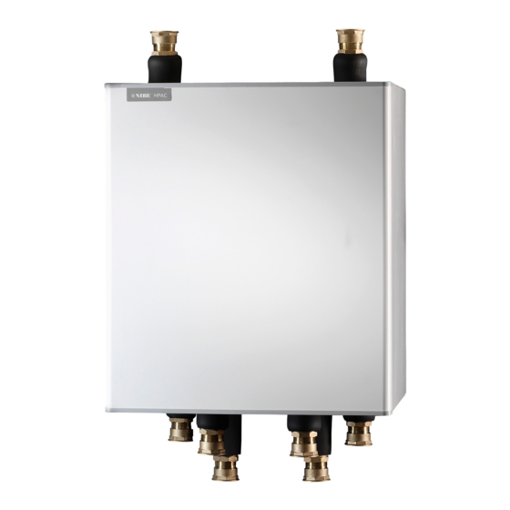
    Deutsch, Installateurhandbuch - HPAC 45 Allgemeines Inhalt Das Zubehör HPAC 45 ist ein Klimamodul für Systeme mit der Wärmepumpe NIBE F1345. Die Wärmepumpe 1 St. Wandhalterung verfügt über ein integriertes Steuersystem zur Regelung von Heizung bzw. Kühlung sowie eingebaute Umwälz- 1 St.
  • Seite 28: Montage

    Einstellungen für die Vorlauftemperatur in Menü 1.9.5. werden (siehe Abb. unten). Liegt ein hoher Kühlbedarf vor und reicht die passive Hängen Sie anschließend HPAC 45 an der Konsole auf. Kühlung nicht aus, wird beim festgelegten Gradminu- HPAC 45 lässt sich nun leicht seitlich verschieben, wo- tenwert die aktive Kühlung zugeschaltet.
  • Seite 29 Umschaltventile Ventilstellungen Der Heiz-/Kühlmodus wird über vier Umschaltventile gesteuert, die je nach herrschender Außenlufttemperatur und je nach Bedarf zwischen unterschiedlichen Stellungen wechseln. QN13 QN15 QN14 QN16 Die Ventilstellung im Ventilgehäuse ist mit zwei Körnungen am der Ventilschaft gekennzeichnet, siehe Abbildung und Tabelle unten.
  • Seite 30 Ventilkontrolle Ventil in Nullstellung Wenn sich die Ventilmotoren gelöst haben und die Ventile nicht mehr an ihren Positionen befinden, korri- gieren Sie die Ventilpositionen z.B. mit einem Schrau- benschlüssel. Justieren Sie die Ventile gemäß „Heizung“ in der Tabel- le oben und montieren Sie die Ventilmotoren ohne Stromzufuhr mit dem Arm in der Nullstellung (Strom ein, Steuerstrom aus).
  • Seite 31: Konstruktion Des Kühlmoduls

    Elektrischer Anschluss Konstruktion des Kühlmoduls AA5-F1 QN16 AA5-X10 AA5-X4 AA5-X9 QN14 QN15 AA5-X2 AA5-S2 QN13 W101 W102 XL17 XL16 QN13 Umschaltventil 1, aktive Kühlung QN14 Umschaltventil 2, passive Kühlung Betriebsschalter QN15 Umschaltventil 3, aktive Kühlung Zubehörplatine QN16 Umschaltventil 4, passive Kühlung Heizungsvorlauf AA5-X2 Anschlussklemme für Fühler und extern ge-...
  • Seite 32: Druckausdehnungsgefäß

    Rohranschluss, Klimatisierungssystem des nungsgefäß (Membrantyp) auszustatten. Ein eventuell Gebäudes vorhandenes Niveaugefäß ist zu ersetzen. Die Wärmepumpe wird an HPAC 45 und einen eventu- Um Betriebsstörungen auszuschließen, ist die Größe ell vorhandenen Brauchwasserspeicher angeschlossen. des Druckausdehnungsgefäßes anhand der Tabelle auszuwählen. Das Druckausdehnungsgefäß arbeitet Der Rohranschluss erfolgt an der Unter- und Oberseite im Temperaturbereich von -10 bis +20°C bei einem...
  • Seite 33 Umschaltventil, Heizung/Brauchwasser RN60 - RN63 Regulierventil RM10 - Rückschlagventil XL27 - XL28 Füllanschluss, Wärmequellenmedium RM13 HPAC 45 Bezeichnungen gemäß Standard IEC 81346-1 und 81346-2. Prinzipskizze F1345 mit HPAC 45 -EB100-BT25 -GP13 -EB100-BT71 -EQ1 -CP20 -BP6 -QN13 -QN14 -QM21 -FL3 -QN15...
  • Seite 34: Elektrischer Anschluss

    Elektriker ausgeführt werden. Bei der Elektroinstallation und beim Verlegen der Leitungen sind die geltenden Vorschriften zu berücksichtigen. 1 2 3 4 F1345 darf bei der Installation von HPAC 45 nicht mit Spannung versorgt werden. HINWEIS! Ein beschädigtes Stromversorgungskabel darf F1345...
  • Seite 35 Elektriker ausgeführt werden. Bei der Elektroinstallation und beim Verlegen der Leitungen sind die geltenden Vorschriften zu berücksichtigen. F1345 darf bei der Installation von HPAC 45 AA5-X2 nicht mit Spannung versorgt werden. Externer Vorlauffühler (BT25) Anschluss von Fühler und extern geschalte- Verbinden Sie den Vorlauffühler zur Wärmepumpe an...
  • Seite 36 Die Programmeinstellung von HPAC 45 kann per Star- ACHTUNG! tassistent oder direkt im Menüsystem des NIBE F1345 Die Relaisausgänge an der Zusatzplatine dür- vorgenommen werden. fen insgesamt mit maximal 2 A (230 V) belastet werden. ACHTUNG! Siehe auch Installateurhandbuch für F1345.
  • Seite 37: Technische Daten

    Technische Daten Maße...
  • Seite 38 Technische Daten Spannung 230 V, 50 Hz Höhe (mm) Breite (mm) Tiefe (mm) Vorgesehen für Wärmepumpen (kW) 20-60 Rohranschluss/Durchflussmesser (mm) G 1 1/2 Zoll Gewicht (kg) Art.nr. 067446...
  • Seite 39: Transporte Y Almacenamiento

    Español, manual de instalación - HPAC 45 Generalidades Contenido El accesorio HPAC 45 es un módulo de inversión de ciclo diseñado para sistemas de bomba de calor NIBE F1345. Soporte de pared La bomba de calor cuenta con un sistema de control integrado que controla la calefacción/refrigeración y...
  • Seite 40: Montaje

    Montaje Control Instale el HPAC 45 utilizando los soportes de montaje El suministro de refrigeración al edificio se regula con suministrados, que deberá atornillar antes tal y como los ajustes de temperatura de caudal definidos en el se muestra en la ilustración.
  • Seite 41 Válvulas inversoras Posiciones de las válvulas Los modos de calefacción/refrigeración se controlan con 4 válvulas inversoras que, en función de la temperatura exterior, alternan entre los dos modos. QN13 QN15 QN14 QN16 La posición de la válvula en su alojamiento va marcada con dos muescas en el eje de la válvula (consulte la imagen y la tabla).
  • Seite 42 Comprobación de la posición de las válvulas Válvula en posición neutra Si algún cabezal de la válvula (motor) se afloja y la po- sición de la válvula se desplaza, ajuste la posición de la válvula con una llave hasta que sea la correcta. Ajuste las válvulas con arreglo a lo indicado para "cale- facción"...
  • Seite 43 Conexión eléctrica Diseño del módulo de refrige- ración AA5-F1 QN16 AA5-X10 AA5-X4 AA5-X9 QN14 QN15 AA5-X2 AA5-S2 W101 W102 QN13 XL17 XL16 Interruptor QN13 Válvula inversora 1, refrigeración activa QN14 Válvula inversora 2, refrigeración pasiva Tarjeta de accesorios QN15 Válvula inversora 3, refrigeración activa AA5-X2 Bloque de terminales, sensores y bloqueo QN16...
  • Seite 44: Conexiones De Tuberías

    El depósito de expansión debe dimensionarse como se indica en la gráfica para evitar problemas de funcio- Conecte la bomba de calor al módulo HPAC 45 y, si procede, al equipo de producción de ACS. namiento. El depósito de expansión admite un rango de temperaturas de -10 °C a +20 °C en el colector a una...
  • Seite 45 Conexión, llenado de solución anticonge- QN10 Válvula inversora, calefacción/ACS lante RM10 - Válvula antirretorno RM13 Designaciones con arreglo a las normas 81346-1 y 81346-2. HPAC 45 Esquema de F1345 con HPAC 45 -EB100-BT25 -GP13 -EB100-BT71 -EQ1 -CP20 -BP6 -QN13 -QN14 -QM21 -FL3...
  • Seite 46: Conexión Eléctrica

    El esquema del circuito eléctrico figura al final de estas instrucciones de instalación. AA5-X4 -X10 Conexión de la alimentación eléctrica El módulo HPAC 45 está equipado de fábrica con cable Tarjeta de de alimentación con enchufe (W101, 3,0 metros de accesorios 2 longitud).
  • Seite 47 La instalación eléctrica y el cableado deben efectuarse según la normativa vigente. La unidad F1345 debe estar apagada al instalar el módulo HPAC 45. AA5-X2 Conexión de los sensores y el bloqueo exter- Sensor de temperatura de caudal externo (BT25) Conecte el sensor de temperatura de caudal a la tarjeta Utilice cable de tipo LiYY, EKKX o similar.
  • Seite 48: Interruptor Dip

    El módulo HPAC 45 se puede configurar a través de la Cuidado guía de puesta en servicio o directamente desde el sis- Las salidas de relé de la tarjeta de accesorios tema de menús de la unidad NIBE F1345. admiten una carga máxima total de 2 A (230 Cuidado Consulte también el manual de instalación de...
  • Seite 49: Especificaciones Técnicas

    Especificaciones técnicas Dimensiones...
  • Seite 50 Características técnicas Tensión 230V 50 Hz Altura (mm) Anchura (mm) Fondo (mm) Para bombas de calor (kW) 20-60 Conexiones de tuberías (mm) G 1 1/2” Peso (kg) Nº de pieza 067446...
  • Seite 51 Elschema/Electrical wiring diagram/Elektrischer schaltplan/Esquema del circuito eléctrico...
  • Seite 56 NIBE AB Sweden Hannabadsvägen 5 Box 14 SE-285 21 Markaryd info@nibe.se www.nibe.eu 331482...

Diese Anleitung auch für:

F1345

Inhaltsverzeichnis