
Verwandte Anleitungen für Lenze EZN3B0055H060N003


Inhaltszusammenfassung für Lenze EZN3B0055H060N003
- Seite 1 EDKZN3BT .73t Montageanleitung Mounting Instructions Instructions de montage Global Drive EZN3B0055H060N003 Anbau−Netzfilter Built−on mains filter Filtre réseau latéral...
- Seite 2 Lesen Sie zuerst diese Anleitung und die Dokumentation zum Grundgerät, bevor Sie mit den Arbeiten beginnen! Beachten Sie die enthaltenen Sicherheitshinweise. Please read these instructions and the documentation of the standard device before you start working! Observe the safety instructions given therein! Lire le présent fascicule et la documentation relative à...
- Seite 3 EZN3T001...
-
Seite 4: Lieferumfang
0Abb. 0Tab. 0 Lieferumfang Anzahl Beschreibung Filter Montageanleitung Beipack mit 4 Befestigungswinkeln und 8 Schrauben M5 x 10 mm (DIN 7985) Elemente am Filter Position Beschreibung Netzanschluss PE−Gewindebolzen Anschluss Grundgerät Typenschild Befestigungswinkel Schrauben für Befestigungswinkel M5 x 10 mm EDKZN3BT DE/EN/FR 1.0... -
Seite 5: Gültigkeit
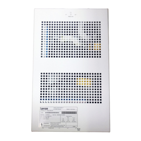
Gültigkeit Diese Anleitung ist gültig für ƒ Anbau−Netzfilter EZN3B0055H060N003 Identifikation Hans-Lenze-Straße 1 D-31855 Aerzen Made in Germany Type: 8200vec080 Abb. 0−1 Typenschild Typenschlüssel xxxx xxxx Produktreihe Zubehör Filtertyp N = Netzfilter Anzahl Phasen 3 = 3 Phasen Grenzwertklasse nach EN 61800−3... -
Seite 6: Dokumenthistorie
© 2007 Lenze Drive Systems GmbH, Hans−Lenze−Straße 1, D−31855 Aerzen Ohne besondere schriftliche Genehmigung von Lenze Drive Systems GmbH darf kein Teil dieser Dokumentation vervielfältigt oder Dritten zugänglich gemacht werden. Wir haben alle Angaben in dieser Dokumentation mit größter Sorgfalt zusammengestellt und auf Übereinstimmung mit der be- schriebenen Hard−... -
Seite 7: Inhaltsverzeichnis
Inhalt Sicherheitshinweise ............Definition der verwendeten Hinweise . -
Seite 8: Sicherheitshinweise
Sicherheitshinweise Definition der verwendeten Hinweise Sicherheitshinweise Definition der verwendeten Hinweise Um auf Gefahren und wichtige Informationen hinzuweisen, werden in dieser Dokumenta- tion folgende Piktogramme und Signalwörter verwendet: Sicherheitshinweise Aufbau der Sicherheitshinweise: Gefahr! (kennzeichnet die Art und die Schwere der Gefahr) Hinweistext (beschreibt die Gefahr und gibt Hinweise, wie sie vermieden werden kann) Piktogramm und Signalwort... -
Seite 9: Restgefahren
Sicherheitshinweise Restgefahren Restgefahren Gefahr! Gefährliche elektrische Spannung Alle Leistungsanschlüsse führen bis zu 3 Minuten nach Netz−Ausschalten gefährliche elektrische Spannung. Mögliche Folgen: Tod oder schwere Verletzungen beim Berühren der Leistungsanschlüsse. ƒ Schutzmaßnahmen: Vor Arbeiten an den Leistungsanschlüssen mindestens 3 Minuten warten. ƒ... - Seite 10 Sicherheitshinweise Restgefahren Stop! Hohes Gerätegewicht Das Gerät ist sehr schwer und muss für die Montage angehoben werden. Mögliche Folgen: Personenschäden, insbesondere Rückenschäden beim Anheben bzw. Halten ƒ des Gerätes Sach− und Personenschäden durch Herunterfallen des Gerätes ƒ Schutzmaßnahmen: Gerät nur mit einer für das Gerätegewicht zugelassenen ƒ...
-
Seite 11: Technische Daten
Technische Daten Allgemeine Daten und Einsatzbedingungen Technische Daten Allgemeine Daten und Einsatzbedingungen Angaben zu Netzen Netzformen mit geerdetem Y−Punkt (TT−/TN−Netze) uneingeschränkte Nutzung IT−Netze Max. Netzspannung 400 V! Anweisungen über besondere Maßnahmen in der Dokumen- tation zum Grundgerät beachten! Schutz Schutzart EN 60529 IP 20 nicht im Anschlussbereich... -
Seite 12: Bemessungsdaten
Technische Daten Bemessungsdaten Bemessungsdaten Hinweis! Das Filter hebt die Ausgangsspannung (Load) gegenüber der Eingangsspannung (Line) um ca. 8 % an. Grundlage der Daten Spannung Spannungsbereich Frequenzbereich Netz f [Hz] 3/PE AC 320 − 0 % ... 440 + 0 % 45 ... -
Seite 13: Mechanische Installation
Mechanische Installation Wichtige Hinweise Mechanische Installation Wichtige Hinweise Der Montageort muss den in den Technischen Daten genannten ƒ Einsatzbedingungen immer entsprechen (¶ 11). Ggf. zusätzliche Maßnahmen ergreifen. Die Montageplatte des Schaltschranks muss folgende Eigenschaften aufweisen: ƒ – elektrisch leitfähig – lackfrei Die mechanischen Verbindungen müssen immer gewährleistet sein. -
Seite 14: Montageschritte
Mechanische Installation Montageschritte Montageschritte EZN3BT005 So montieren Sie das Filter: 1. Lesen Sie in der Dokumentation des Grundgerätes das Kapitel "Mechanische Installation". Informieren Sie sich insbesondere über ... – Vorsichtsmaßnahmen während der Montage – das benötigte Montagematerial – die vorgeschriebenen Anzugsmomente –... -
Seite 15: Elektrische Installation
Elektrische Installation Wichtige Hinweise Elektrische Installation Wichtige Hinweise Die Installation muss ƒ – den in den Technischen Daten genannten Einsatzbedingungen immer entsprechen (¶ 11). – nach EN 60204−1 ausgeführt werden. Bei der Auswahl des Leitungstyps beachten: ƒ – Die verwendeten Leitungen müssen den geforderten Approbationen am Einsatzort entsprechen (z. -
Seite 16: Anschlussdaten
Elektrische Installation Anschlussdaten Anschlussdaten Klemmen "Line" [Nm] [AWG] [lb−in] 4 ... 4.5 EZN3B0055H060 10 ... 25 4 ... 25 2.5 ... 10 2 ... 10 35.4 ... 39.8 PE−Gewindebolzen [mm] [Nm] [lb−in] EZN3B0055H060 M8 x 25 SW 10 106.2 Anschlussleitung "Load" EZN3B0055H060 EDKZN3BT DE/EN/FR 1.0... -
Seite 17: Montageschritte
Elektrische Installation Montageschritte Montageschritte EZN3BT004 So verdrahten Sie das Filter: 1. Anschlussleitungen "Load" 2 am Grundgerät anschließen. – Montageanleitung des Grundgerätes beachten! 2. PE−Leiter mit Ringkabelschuh an PE−Gewindebolzen 1 montieren. – Anzugsmoment beachten! 3. Netzleitungen an Schraubklemme "Line" 0 anschließen. –... -
Seite 18: Scope Of Supply
0Fig. 0Tab. 0 Scope of supply Quantity Description Filter Mounting Instructions Accessory kit with 4 fixing brackets and 8 screws M5 x 10 mm (DIN 7985) Elements on the filter Position Description Mains connection PE stud Basic device connection Nameplate Fixing bracket Screws for fixing bracket M5 x 10 mm EDKZN3BT DE/EN/FR 1.0... -
Seite 19: Range Of Application
Validity These instructions are valid for ƒ Built−on mains filter EZN3B0055H060N003 Identification Hans-Lenze-Straße 1 D-31855 Aerzen Made in Germany Type: 8200vec080 Fig.0−1 Nameplate Type code xxxx xxxx Product series Accessories Type of filter N = mains filter Number of phases 3 = 3 phases Limit class according to EN 61800−3... -
Seite 20: Document History
© 2007 Lenze Drive Systems GmbH, Hans−Lenze−Straße 1, D−31855 Aerzen No part of this documentation may be reproduced or made accessible to third parties without written consent by Lenze Drive Systems GmbH. All information given in this documentation has been selected carefully and complies with the hardware and software described. - Seite 21 Contents Safety instructions ............Definition of notes used .
-
Seite 22: Safety Instructions
Safety instructions Definition of notes used Safety instructions Definition of notes used The following pictographs and signal words are used in this documentation to indicate dangers and important information: Safety instructions Structure of safety instructions: Danger! (characterises the type and severity of danger) Note (describes the danger and gives information about how to prevent dangerous situations) -
Seite 23: Residual Hazards
Safety instructions Residual hazards Residual hazards Danger! Dangerous voltage All power terminals remain live for at least three minutes after mains disconnection. Possible consequences: Death or severe injuries when touching the power terminals. ƒ Protective measures: Wait for at least three minutes before working on the power terminals. ƒ... - Seite 24 Safety instructions Residual hazards Stop! Heavy device weight The device is very heavy and must be lifted for the mounting. Possible consequences: Injury to persons, particularly backache when lifting and holding the device, ƒ respectively Injury to persons and damage to material assets due to the device falling ƒ...
-
Seite 25: Technical Data
Technical data General data and operating conditions Technical data General data and operating conditions Mains data Mains types With grounded neutral (TT/TN systems) Operation permitted without restrictions IT systems Max. mains voltage 400 V! Observe instructions for special measures in the documentation for the basic device! Protection Degree of protection... -
Seite 26: Rated Data
Technical data Rated data Rated data Note! Due to the filter, the output voltage (load) is 8 % higher than the input voltage (line). Basis of the data Voltage Voltage range Frequency range Mains f [Hz] 3/PE AC 320 − 0 % ... 440 + 0 % 45 ... -
Seite 27: Mechanical Installation
Mechanical installation Important notes Mechanical installation Important notes The mounting location must always fulfill the operating conditions specified in the ƒ Technical data. (¶ 25). If necessary, take additional measures. The mounting plate of the control cabinet must be: ƒ –... -
Seite 28: Mounting Steps
Mechanical installation Mounting steps Mounting steps EZN3BT005 How to mount the filter: 1. Read the chapter "Mechanical installation" in the documentation of the basic device. Read up particularly on ... – Precautionary measures while mounting – Installation material required – Compulsory starting torques –... -
Seite 29: Electrical Installation
Electrical installation Important notes Electrical installation Important notes Installation must ƒ – always be in accordance with the operating conditions specified in the Technical data (¶ 25). – be carried out to EN 60204−1. Please observe the following when selecting the cable type: ƒ... -
Seite 30: Connection Data
Electrical installation Connection data Connection data Terminals "line" [Nm] [AWG] [lb−in] 4 ... 4.5 EZN3B0055H060 10 ... 25 4 ... 25 2.5 ... 10 2 ... 10 35.4 ... 39.8 PE stud [mm] [Nm] [lb−in] EZN3B0055H060 M8 x 25 SW 10 106.2 "Load"... -
Seite 31: Mounting Steps
Electrical installation Mounting steps Mounting steps EZN3BT004 How to wire the filter: 1. Connect the connection cables "load" 2 to the basic device. – Observe the mounting instructions for the basic device! 2. Attach the PE conductor to the PE stud 1 with the ring cable lug. –... -
Seite 32: Equipement Livré
0Fig. 0Tab. 0 Equipement livré Nombre Description Filtre Instructions de montage Kit de montage comprenant 4 équerres de fixation et 8 vis M5 x 10 mm (DIN 7985) Eléments du filtre Position Description Raccordement réseau Boulons filtetés PE Raccordement de l’appareil de base Plaque signalétique Equerre de fixation Vis pour équerre de fixation M5 x 10 mm... -
Seite 33: Domaine D'utilisation
Validité Le présent document s’applique aux modules suivants : ƒ Filtre réseau latéral EZN3B0055H060N003 Identification Hans-Lenze-Straße 1 D-31855 Aerzen Made in Germany Type: 8200vec080 Fig.0−1 Plaque signalétique Codification des types xxxx xxxx Série d’appareils Accessoires Type de filtre N = filtre réseau... - Seite 34 TD29 Première édition Conseil ! Les mises à jour de logiciels et les documentations récentes relatives aux produits Lenze sont disponibles dans la zone "Téléchargements" du site Internet : http://www.Lenze.com © 2007 Lenze Drive Systems GmbH, Hans−Lenze−Straße 1, D−31855 Aerzen Toute représentation ou reproduction, en tout ou en partie et par quelque procédé...
- Seite 35 Sommaire Consignes de sécurité ............Définition des conventions utilisées .
-
Seite 36: Consignes De Sécurité
Consignes de sécurité Définition des conventions utilisées Consignes de sécurité Définition des conventions utilisées Pour indiquer des risques et des informations importantes, la présente documentation utilise les mots et symboles suivants : Consignes de sécurité Présentation des consignes de sécurité Danger ! (Le pictogramme indique le type de risque.) Explication... -
Seite 37: Dangers Résiduels
Consignes de sécurité Dangers résiduels Dangers résiduels Danger ! Tension électrique dangereuse Les raccordements de puissance sont encore sous tension jusqu’à 3 minutes après la coupure réseau. Risques encourus Mort ou blessures graves en cas de contact accidentel avec les ƒ... - Seite 38 Consignes de sécurité Dangers résiduels Stop ! Appareil lourd Cet appareil est très lourd et doit être soulevé pour le montage. Risques encourus : Blessures, notamment lombalgies causées par le fait de soulever ou de ƒ maintenir l’appareil Blessures et dommages matériels causés par une chute de l’appareil ƒ...
-
Seite 39: Spécifications Techniques
Spécifications techniques Caractéristiques générales et conditions d’utilisation Spécifications techniques Caractéristiques générales et conditions d’utilisation Informations sur les réseaux Configurations réseau Avec point Y à la terre (réseaux TT/TN) Utilisation sans restriction Réseaux IT Tension réseau maxi. 400 V ! Respecter les indications concernant les mesures particulières dans la documentation de l’appareil de base ! Protection Indice de protection... -
Seite 40: Caractéristiques Nominales
Spécifications techniques Caractéristiques nominales Caractéristiques nominales Remarque importante ! Avec le filtre, la tension de sortie (Load) augmente d’environ 8% par rapport à la tension d’entrée (Line). Données de base Tension Plage de tension Plage de fréquence Réseau f [Hz] 3/PE CA 320 −... -
Seite 41: Installation Mécanique
Installation mécanique Remarques importantes Installation mécanique Remarques importantes Le lieu de montage doit toujours respecter les conditions d’utilisation indiquées ƒ dans les spécifications techniques (¶ 39). Si besoin est, prendre des mesures supplémentaires. La plaque de montage de l’armoire électrique doit être : ƒ... -
Seite 42: Opérations De Montage
Installation mécanique Opérations de montage Opérations de montage EZN3BT005 Pour monter le filtre : 1. Dans le documentation de l’appareil de base, lire le chapitre "Installation mécanique". Accorder une attention particulière aux points suivants : – Mesures de précaution à prendre pour le montage –... -
Seite 43: Installation Électrique
Installation électrique Remarques importantes Installation électrique Remarques importantes L’installation doit ƒ – toujours respecter les conditions d’utilisation indiquées dans les spécifications techniques (¶ 39) ; – répondre aux exigences de la norme EN 60204−1. Lors du choix du type de câble, tenir compte des points suivants : ƒ... -
Seite 44: Données De Raccordement
Installation électrique Données de raccordement Données de raccordement Bornes "Line" [Nm] [AWG] [lb−in] 4 ... 4.5 EZN3B0055H060 10 ... 25 4 ... 25 2.5 ... 10 2 ... 10 35.4 ... 39.8 Boulon fileté PE [mm] [Nm] [lb−in] EZN3B0055H060 M8 x 25 SW 10 106.2 Câble de raccordement "Load"... -
Seite 45: Opérations De Montage
Installation électrique Opérations de montage Opérations de montage EZN3BT004 Pour raccorder le filtre : 1. Raccorder les câbles "Load" 2 à l’appareil de base. – Tenir compte des instructions de montage de l’appareil de base ! 2. Raccorder le conducteur PE avec cosse à oeillet au boulon PE 1 montieren. –... - Seite 46 Lenze Drive Systems GmbH EDKZN3BT Hans−Lenze−Straße 1 DE/EN/FR 1.0 D−31855 Aerzen © 09/2007 Germany TD29 +49 (0) 51 54 82−0 Service 00 80 00 24 4 68 77 (24 h helpline) Ê Service +49 (0) 51 54 82−1112 E−Mail Lenze@Lenze.de Internet www.Lenze.com...