Kapitel
Inhaltsverzeichnis
Fehlerbehebung

Verwandte Anleitungen für Lenze E82MV302


Inhaltszusammenfassung für Lenze E82MV302
- Seite 1 EDK82MV752 .G|÷ Montageanleitung Mounting Instructions Instructions de montage 8200 motec 3.0 ... 7.5 kW E82MVxxx_4Bxxx Frequenzumrichter Frequency inverter Convertisseur de fréquence...
- Seite 2 Lesen Sie zuerst diese Anleitung, bevor Sie mit den Arbeiten beginnen! Beachten Sie die enthaltenen Sicherheitshinweise. Ausführliche Informationen finden Sie in der Betriebsanleitung. Read these instructions before you start working! Follow the safety instructions given. More detailed information can be found in the Operating Instructions. Veuillez lire attentivement cette documentation avant toute action ! Les consignes de sécurité...
- Seite 3 001 = Standardausführung, verlackt 151 = Kühlkörper pulverbeschichtet 152 = Ausgang K1 als Transistor−Schalter 230 = Betrieb mit 30 mA−Fehlerstrom−Schutzschalter Hardwarestand Softwarestand 0Abb. 0Tab. 0 Tipp! Informationen und Hilfsmittel rund um die Lenze−Produkte finden Sie im Download−Bereich unter www.lenze.com EDK82MV752 DE/EN/FR 7.2...
- Seite 4 Inbetriebnahme 8200 motec ohne Funktionsmodul Der 8200 motec ist nur funktionsfähig mit aufgesteckter FIF−Abdeckkappe 0! (Ausliefe- rungszustand). – Ohne die FIF−Abdeckkappe ist der 8200 motec gesperrt (Keypad: dc). Da der 8200 motec ohne Funktionsmodul keine Steuerklemmen hat, kann das Starten und Stoppen während des Betriebs auch über Netzschalten erfolgen.
-
Seite 5: Inhaltsverzeichnis
........Allgemeine Sicherheits− und Anwendungshinweise für Lenze−Motoren . - Seite 6 Inhalt Inbetriebnahme ............Vor dem ersten Einschalten .
-
Seite 7: Über Diese Dokumentation
Über diese Dokumentation Verwendete Konventionen Über diese Dokumentation Informationen zur Gültigkeit Diese Anleitung ist gültig für Frequenzumrichter E82MV302 ƒ Frequenzumrichter E82MV402 ƒ Frequenzumrichter E82MV552 ƒ Frequenzumrichter E82MV752 ƒ Zielgruppe Diese Dokumentation richtet sich an qualifiziertes Fachpersonal nach IEC 60364. Qualifiziertes Fachpersonal sind Personen, die für die auszuführenden Tätigkeiten bei der Aufstellung, Montage, Inbetriebsetzung und dem Betrieb des Produkts über entspre-... -
Seite 8: Verwendete Hinweise
Über diese Dokumentation Verwendete Hinweise Verwendete Hinweise Um auf Gefahren und wichtige Informationen hinzuweisen, werden in dieser Dokumenta- tion folgende Piktogramme und Signalwörter verwendet: Sicherheitshinweise Aufbau der Sicherheitshinweise: Gefahr! (kennzeichnet die Art und die Schwere der Gefahr) Hinweistext (beschreibt die Gefahr und gibt Hinweise, wie sie vermieden werden kann) Piktogramm und Signalwort Bedeutung Gefahr von Personenschäden durch gefährliche elektrische... -
Seite 9: Bestimmungsgemäße Verwendung
Über diese Dokumentation Bestimmungsgemäße Verwendung Bestimmungsgemäße Verwendung Frequenzumrichter 8200 motec und Zubehör sind Komponenten ƒ – zur Steuerung und Regelung von drehzahlveränderbaren Antrieben mit Asynchron−Normmotoren, Reluktanzmotoren, PM−Synchronmotoren mit asynchronem Dämpferkäfig. – zum Einbau in eine Maschine. – zum Zusammenbau mit anderen Komponenten zu einer Maschine. dürfen nur unter den in dieser Dokumentation vorgeschriebenen ƒ... -
Seite 10: Sicherheitshinweise
Vorschläge, deren Übertragbarkeit auf die jeweilige Anwen- dung überprüft werden muss. Für die Eignung der angegebenen Verfahren und Schal- tungsvorschläge übernimmt der Hersteller keine Gewähr. Alle Arbeiten mit und an Lenze−Antriebs− und Automatisierungskomponenten darf ƒ nur qualifiziertes Fachpersonal ausführen. - Seite 11 Sicherheitshinweise Allgemeine Sicherheitshinweise Transport, Lagerung Transport und Lagerung in trockener, schwingungsarmer Umgebung ohne ƒ aggressiver Atmosphäre; möglichst in der Hersteller−Verpackung. – Vor Staub und Stößen schützen. – Klimatische Bedingungen gemäß den Technischen Daten einhalten. Mechanische Installation Das Produkt nach den Vorschriften der zugehörigen Dokumentation aufstellen. ƒ...
- Seite 12 Sicherheitshinweise Allgemeine Sicherheitshinweise Wartung und Instandhaltung Die Komponenten sind wartungsfrei, wenn die vorgeschriebenen ƒ Einsatzbedingungen eingehalten werden. Bei verunreinigter Umgebungsluft können Kühlflächen verschmutzen oder ƒ Kühlöffnungen verstopft werden. Bei diesen Betriebsbedingungen deshalb regelmäßig die Kühlflächen und Kühlöffnungen reinigen. Dazu niemals scharfe oder spitze Gegenstände verwenden! Nachdem das System von der Versorgungsspannung getrennt ist, dürfen Sie ƒ...
-
Seite 13: Allgemeine Sicherheits− Und Anwendungshinweise Für Lenze−Motoren
Sicherheitshinweise Allgemeine Sicherheits− und Anwendungshinweise für Lenze−Motoren Allgemeine Sicherheits− und Anwendungshinweise für Lenze−Motoren (gemäß Niederspannungsrichtlinie 2006/95/EG) Allgemein Niederspannungsmaschinen haben gefährliche, spannungsführende und rotierende Teile sowie möglicherweise heiße Oberflächen. Bei Synchronmaschinen werden bei drehender Maschine auch an den offenen Klemmen Spannungen induziert. - Seite 14 Sicherheitshinweise Allgemeine Sicherheits− und Anwendungshinweise für Lenze−Motoren Aufstellung Auf plane Auflage, gute Fuß− bzw. Flanschbefestigung und genaue Ausrichtung bei direk- ter Kupplung achten. Aufbaubedingte Resonanzen mit der Drehfrequenz und der doppel- ten Speisefrequenz vermeiden. Läufer von Hand drehen, auf ungewöhnliche Schleif- geräusche achten.
- Seite 15 Sicherheitshinweise Allgemeine Sicherheits− und Anwendungshinweise für Lenze−Motoren Inbetriebnahme und Betrieb Vor Inbetriebnahme nach längerer Lagerzeit den Isolationswiderstand messen. Bei Wer- ten £ 1 kW je Volt Bemessungsspannung die Wicklung trocknen. Für den Probebetrieb ohne Abtriebselemente die Passfeder sichern. Schutzeinrichtungen auch im Probebetrieb nicht außer Funktion setzen.
-
Seite 16: Restgefahren
Sicherheitshinweise Restgefahren Restgefahren Personenschutz Lenze−Antriebsregler (Frequenzumrichter, Servo−Umrichter, Stromrichter) und ƒ zugehörige Komponenten können während des Betriebs − ihrer Schutzart entsprechend − spannungsführende, auch bewegliche oder rotierende Teile haben. Oberflächen können heiß sein. – Bei unzulässigem Entfernen der erforderlichen Abdeckung, bei unsachgemäßem Einsatz, bei falscher Installation oder Bedienung besteht die Gefahr von schweren Personen−... - Seite 17 – Weitgehenden Schutz gegen Überlastung bietet der Einsatz eines Überstromrelais oder einer Temperaturüberwachung. – Wir empfehlen zur Temperaturüberwachung des Motors, PTC (Kaltleiter) oder Thermokontakte einzusetzen. (Lenze−Drehstrommotoren sind standardmäßig mit Thermokontakten (Öffner) bestückt) – PTC oder Thermokontakte können am Antriebsregler angeschlossen werden.
-
Seite 18: Technische Daten
Technische Daten Allgemeine Daten und Einsatzbedingungen Technische Daten Allgemeine Daten und Einsatzbedingungen Konformität und Approbation Konformität 2006/95/EG Niederspannungsrichtlinie 2004/108/EG EMV−Richtlinie TP TC 020/2011 Elektromagnetische Ver- Eurasische Konformität träglichkeit von techni- (TR ZU 020/2011) TR ZU: Technische Regulierung schen Erzeugnissen der Zollunion TP TC 004/2011 Über die Sicherheit von Eurasische Konformität... - Seite 19 250 mm terbaugruppe E82ZMV Hinweis zum Betrieb mit Lüfterbaugruppe E82ZMV: Die Lüfterbaugruppe muss immer eingesetzt werden bei Wandmontage des motec Betrieb ohne Stromreduzierung mit eigenbelüfteten Lenze−Motoren oder Lenze− Getriebemotoren Betrieb mit Fremdmotor ^ Kapitel "Mechanische Installation" Abmessungen, ^ Kapitel "Technische Daten", "Betrieb mit Bemessungsleistung" oder "Betrieb mit Gewichte erhöhter Bemessungsleistung"...
-
Seite 20: Betrieb Mit Bemessungsleistung (Normalbetrieb)
24.8 Die Ausgangsströme gelten für den Betrieb mit Lüfterbaugruppe E82ZMV oder mit fremdbelüfteten Lenze−Motoren/Getriebemotoren. Bei Betrieb mit eigenbelüfteten Lenze−Motoren/Getriebemotoren muss der Ausgangs−Bemessungstrom reduziert werden (siehe Abbildung) Ströme für periodisches Lastwechselspiel: 1 min Überstromdauer mit I und 2 min Grundlastdauer mit 75 % I Masse incl. -
Seite 21: Abmessungen
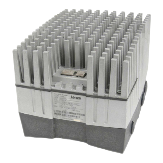
Technische Daten Abmessungen Abmessungen 82mot443 a [mm] b [mm] c [mm] d [mm] e [mm] E82MV302_4B E82MV402_4B (208, incl. Lüfterbau- E82MV552_4B (incl. Dichtung) (incl. Dichtung) gruppe) E82MV752_4B Mechanische Ausführung Verschraubungen Gewicht E82MV302_4B 9.9 kg E82MV402_4B 3 × M25, 4 × M16 (11.7 kg incl. -
Seite 22: Mechanische Installation
Mechanische Installation motec mit Motor oder Getriebemotor Mechanische Installation motec mit Motor oder Getriebemotor Gefahr! Alle Steuerklemmen sind nach dem Anschluss eines Kaltleiters (PTC) oder ƒ eines Thermokontakts nur noch basisisoliert (einfache Trennstrecke). Berührsicherheit bei defekter Trennstrecke ist nur durch externe ƒ... -
Seite 23: Emv−Gerechte Verdrahtung (Ce−Typisches Antriebssystem)
Mechanische Installation motec mit Motor oder Getriebemotor EMV−gerechte Verdrahtung (CE−typisches Antriebssystem) 4.1.1 EMV−gerechte Verdrahtung (CE−typisches Antriebssystem) Bedingungen für störungsfreien Betrieb: Mit Ausnahme der Netzleitung nur geschirmte Leitungen verwenden. ƒ Schirmung sorgfältig auf PE legen (siehe unten). ƒ Motor− und Netz−Schutzleiter an getrennte PE−Klemmen schrauben. ƒ... -
Seite 24: Wandmontage
Mechanische Installation Wandmontage Lieferumfang Wandmontage Hinweis! Beachten Sie bitte, dass die Wandmontage eines 8200 motec in der Variante V230 nicht möglich ist. 4.2.1 Lieferumfang M5 x 65 8200mot449 8200 motec (Elektronikmodul und Trägergehäuse) Adapterplatte Flachdichtungen für Adapterplatte Halterung für Funktionsmodule und elektrischen Anschluss der Lüfterbaugruppe Lüfterbaugruppe E82ZMV 4 Schrauben M5 ×... -
Seite 25: Vorbereitung
Mechanische Installation Wandmontage Vorbereitung 4.2.2 Vorbereitung Stop! Der motec kann durch thermische Überlastung zerstört werden! Bei der Wandmontage müssen Sie zusätzlich die Lüfterbaugruppe E82ZMV montieren, um eine ausreichende Kühlung des motec zu gewährleisten. Æ 5 mm 8200mot402 1. Adapterplatte vormontieren: –... -
Seite 26: Motoranschluss
Mechanische Installation Wandmontage Motoranschluss 4.2.3 Motoranschluss Gefahr! Alle Steuerklemmen sind nach dem Anschluss eines Kaltleiters (PTC) oder ƒ eines Thermokontakts nur noch basisisoliert (einfache Trennstrecke). Berührsicherheit bei defekter Trennstrecke ist nur durch externe ƒ Maßnahmen gewährleistet, z. B. doppelte Isolierung. 8200mot468 Kapazitätsarme Motorleitungen verwenden! (Ader/Ader £... -
Seite 27: Emv−Gerechte Verdrahtung (Ce−Typisches Antriebssystem)
Mechanische Installation Wandmontage EMV−gerechte Verdrahtung (CE−typisches Antriebssystem) 4.2.4 EMV−gerechte Verdrahtung (CE−typisches Antriebssystem) Bedingungen für störungsfreien Betrieb: Außer der Netzleitung nur geschirmte Leitungen verwenden. ƒ Schirmung sorgfältig auf PE legen (siehe unten). ƒ Steuer− und Netzleitung räumlich getrennt von Motorleitung verlegen! ƒ... -
Seite 28: Motormontage
Mechanische Installation Motormontage Lieferumfang Motormontage 4.3.1 Lieferumfang M5 x 65 8200mot449 8200 motec (Elektronikmodul und Trägergehäuse) Adapterplatte Flachdichtungen für Adapterplatte Halterung für Funktionsmodule und elektrischen Anschluss der Lüfterbaugruppe Lüfterbaugruppe E82ZMV 4 Schrauben M5 × 65 mm zur Befestigung des Trägergehäuses auf der Lüfterbaugruppe EDK82MV752 DE/EN/FR 7.2... -
Seite 29: Vorbereitung
Mechanische Installation Motormontage Vorbereitung 4.3.2 Vorbereitung Stop! Wenn Sie keinen Lenze−Motor/Getriebemotor einsetzen, müssen Sie ƒ zusätzlich die Lüfterbaugruppe E82ZMV montieren, um eine ausreichende Kühlung des motec zu ermöglichen. Wenn Sie einen eigenbelüfteten Lenze−Motor/Getriebemotor und keine ƒ Lüfterbaugruppe einsetzen, ist der Betrieb des motec nur mit reduziertem Ausgangsstrom zulässig. - Seite 30 Mechanische Installation Motormontage Vorbereitung 1. Klemmenkasten des Motors entfernen – Bei beengten Platzverhältnissen auch das Klemmenbrett des Motors entfernen. 2. Motoranschlussdrähte für die Verbindung von Klemmbrett zu Klemme X2 mit dem Klemmbrett verbinden – Leitungslänge 20 cm 3. Am Trägergehäuse Kabeldurchführungen festlegen und die Öffnungen herausbrechen 4.
-
Seite 31: Motoranschluss
Mechanische Installation Motormontage Motoranschluss 4.3.3 Motoranschluss Gefahr! Alle Steuerklemmen sind nach dem Anschluss eines Kaltleiters (PTC) oder ƒ eines Thermokontakts nur noch basisisoliert (einfache Trennstrecke). Berührsicherheit bei defekter Trennstrecke ist nur durch externe ƒ Maßnahmen gewährleistet, z. B. doppelte Isolierung. 8200mot408 8200mot408 X2/PE2... -
Seite 32: Emv−Gerechte Verdrahtung (Ce−Typisches Antriebssystem)
Mechanische Installation Motormontage EMV−gerechte Verdrahtung (CE−typisches Antriebssystem) 4.3.4 EMV−gerechte Verdrahtung (CE−typisches Antriebssystem) Bedingungen für störungsfreien Betrieb: Mit Ausnahme der Netzleitung nur geschirmte Leitungen verwenden. ƒ Schirmung sorgfältig auf PE legen (siehe unten). ƒ Motor− und Netz−Schutzleiter an getrennte PE−Klemmen schrauben. ƒ... -
Seite 33: Elektrische Installation
Elektrische Installation Netzanschluss Elektrische Installation Netzanschluss Gefahr! Gefährliche elektrische Spannung Der Ableitstrom gegen Erde (PE) ist > 3,5 mA AC bzw. 10 mA DC. Mögliche Folgen: Tod oder schwere Verletzungen beim Berühren des Gerätes im Fehlerfall. ƒ Schutzmaßnahmen: Die in der EN 61800−5−1 geforderten Maßnahmen umsetzen. Insbesondere: ƒ... - Seite 34 Elektrische Installation Netzanschluss Beachten Sie bei Einsatz von Fehlerstrom−Schutzschaltern Fehlerstrom−Schutzschalter nur zwischen speisendem Netz und Antriebsregler ƒ installieren. Fehlerstrom−Schutzschalter kann falsch auslösen durch ƒ – kapazitive Ausgleichsströme der Leitungsschirme während des Betriebs (vor allem bei langen, geschirmten Motorleitungen), – gleichzeitiges Zuschalten mehrerer Antriebsregler ans Netz, –...
-
Seite 35: Anschluss Relaisausgang
Elektrische Installation Anschluss Relaisausgang Anschluss Relaisausgang 8200mot410 Meldung Funktion Relaisstellung (Lenze−Einstellung) Technische Daten X1/K11 Öffner geöffnet TRIP AC 250 V/3 A X1/K12 Mittelkontakt DC 24 V/2 A ... DC 240 V/0.22 A X1/K14 Schließer geschlossen TRIP HF−Schirmabschluss durch großflächige Anbindung an PE... -
Seite 36: Anschluss Digitaler Schaltausgang (Nur Bei Geräteausführung 152)
+ 20 V (+12 V ... spannung +30 V DC) Masse der geschaltete Ausgang wird durch "TRIP" signalisiert (Lenze−Einstellung) Stop! Zum Schutz des Schaltausgangs vor Überspannungen beim Betrieb mit Induktivitäten ist eine Freilaufdiode (z.B. 1N4148) parallel zu schalten (siehe Bild unten). -
Seite 37: Montage Funktionsmodul (Option)
Elektrische Installation Montage Funktionsmodul (Option) Montage Funktionsmodul (Option) Stop! Steuerleitungen immer abschirmen um Störeinkopplungen zu vermeiden! ƒ Die FIF−Abdeckkappe am Elektronikmodul und die Schutzkappen der ƒ Funktionsmodule entfernen. Sonst können der motec und die Funktionsmodule beschädigt werden! Kombinationsfähig mit (Bus−)Funktionsmodulen ist das Bus−I/O ƒ... - Seite 38 Elektrische Installation Montage Funktionsmodul (Option) Hinweis! Reglerfreigabe (Klemme 28) wird ausschließlich auf Steckplatz 1 ausgewertet! Klemme 28 des Funktionsmoduls auf Steckplatz 2 ist inaktiv. 1. Am Trägergehäuse Kabeldurchführungen festlegen und die Öffnungen herausbrechen 2. Verschraubungen einsetzen 3. Leitungen, die in das Trägergehäuse geführt werden, abisolieren. Für alle geschirmten Leitungen gilt: –...
-
Seite 39: Motec Zusammenbauen
Elektrische Installation motec zusammenbauen motec zusammenbauen 5.5.1 motec mit Funktionsmodulen Stop! Vor dem Zusammenbau unbedingt Schutzkappe des Funktionsmoduls 1 ƒ und FIF−Abdeckkappe 0 entfernen und aufbewahren! Sonst kann der motec beschädigt werden! Vor Inbetriebnahme mit dem Aufkleber 2, der dem Funktionsmodul ƒ... -
Seite 40: Inbetriebnahme
Inbetriebnahme Vor dem ersten Einschalten Inbetriebnahme Vor dem ersten Einschalten Hinweis! Halten Sie die jeweilige Einschaltreihenfolge ein. ƒ Bei Störungen während der Inbetriebnahme hilft Ihnen das Kapitel ƒ "Fehlersuche und Störungsbeseitigung". Um Personenschäden oder Sachschäden zu vermeiden, überprüfen Sie vor dem Zuschalten der Netzspannung: Die Verdrahtung auf Vollständigkeit, Kurzschluss und Erdschluss ƒ... -
Seite 41: Betriebsart Wählen
Inbetriebnahme Betriebsart wählen Betriebsart wählen Über die Betriebsart wählen Sie die Steuerungsart oder Regelungsart des Antriebsreglers aus. Sie können wählen zwischen U/f−Kennliniensteuerung ƒ Vectorregelung ƒ Sensorlose Drehmomentregelung ƒ Die U/f−Kennliniensteuerung ist die klassische Betriebsart für Standardanwendungen. Mit der Vector−Regelung erzielen Sie gegenüber der U/f−Kennliniensteuerung verbesserte Antriebseigenschaften durch: höheres Drehmoment über den gesamten Drehzahlbereich ƒ... - Seite 42 Inbetriebnahme Betriebsart wählen Empfohlene Betriebsarten für Standardanwendungen Für Standardanwendungen hilft Ihnen die folgende Tabelle, die richtige Betriebsart zu wählen: Anwendung Betriebsart Einstellung in C0014 empfohlen alternativ Einzelantriebe mit stark wechselnden Lasten mit Schweranlauf mit Drehzahlregelung (Drehzahlrückführung) mit hoher Dynamik (z. B. Positionier− und Zustellantriebe) −...
-
Seite 43: Parametrierung Mit Dem Handterminal E82Zbb
Inbetriebnahme Parametrierung mit dem Handterminal E82ZBB Parametrierung mit dem Handterminal E82ZBB Beschreibung Das Handterminal ist als Zubehör erhältlich. Das Handterminal besteht aus einer gum- mierten Hülle in der das Keypad E82ZBC montiert ist. Für den Anschluss an den Antriebs- regler benötigen Sie eine separate Anschlussleitung Typ E82ZWL. Die vollständige Be- schreibung des Keypads finden Sie in der im Lieferumfang beiliegenden Anleitung. -
Seite 44: U/F−Kennliniensteuerung
DIP−Schalter auf dem Standard−I/O auf den gleichen wertvorgabe an (C0034) Bereich einstellen (siehe Montageanleitung des Stan- dard−I/O) Lenze−Einstellung: −0−, (0 ... 5 V/0 ... 10 V/0 ... 20 mA) Passen Sie die Klemmenkonfiguration an die Verdrahtung an (C0007) Lenze−Einstellung: −0−, d. h. -
Seite 45: Vector−Regelung
DIP−Schalter auf dem Standard−I/O auf den gleichen wertvorgabe an (C0034) Bereich einstellen (siehe Montageanleitung des Stan- dard−I/O) Lenze−Einstellung: −0−, (0 ... 5 V/0 ... 10 V/0 ... 20 mA) Geben Sie die Motordaten ein Siehe Motor−Typenschild Motor−Bemessungsdrehzahl (C0087) Lenze−Einstellung: 1390 rpm Motor−Bemessungsstrom (C0088) - Seite 46 Inbetriebnahme Vector−Regelung Einschaltreihenfolge Bemerkung Starten Sie die Motorparameter−Identifizierung (C0148) Nur bei kaltem Motor durchführen! Sicherstellen, dass der Regler gesperrt ist Klemme X3/28 = LOW v drücken C0148 = 1 einstellen Regler freigeben Klemme X3/28 = HIGH Die Identifizierung startet: – Das Segment c erlischt –...
-
Seite 47: Vectorregelung Optimieren
Inbetriebnahme Vector−Regelung Vectorregelung optimieren Die Vectorregelung ist nach der Motorparameter−Identifizierung in der Regel ohne weitere Maßnahmen betriebsfähig. Sie müssen die Vectorregelung nur bei folgendem Antriebs- verhalten optimieren: Antriebsverhalten Abhilfe Rauer Motorlauf und Motorstrom (C0054) > 60 % Mo- 1. Motor−Ständerinduktivität (C0092) um 10 % verrin- tor−Bemessungsstrom im Maschinenleerlauf (stationä- gern rer Betrieb) -
Seite 48: Wichtige Antriebsregler−Codestellen
Code, Subcode oder Auswahl nur verfügbar bei Betrieb mit Application−I/O Code ist in der Lenze−Einstellung im USER−Menü enthalten uSEr Bezeichnung Bezeichnung des Code Lenze Lenze−Einstellung (Wert bei Auslieferung oder nach Wiederherstellen des Liefer- zustands mit C0002) à Die Spalte "WICHTIG" enthält weitere Information Auswahl 99 min. Wert {Einheit} max. - Seite 49 Lenze−Einstellung ð PAR3 Lenze−Einstellung ð PAR4 Lenze−Einstellung ð FPAR1 Lieferzustand wiederherstellen im Feldbus−Funktionsmodul Lenze−Einstellung ð PAR1 + FPAR1 Lieferzustand wiederherstellen im ge- wählten Parametersatz des Antriebs- Lenze−Einstellung ð PAR2 + FPAR1 reglers und im Feldbus−Funktionsmo- Lenze−Einstellung ð PAR3 + FPAR1 Lenze−Einstellung ð...
- Seite 50 Inbetriebnahme Wichtige Antriebsregler−Codestellen Code Einstellmöglichkeiten WICHTIG Bezeichnung Lenze Auswahl Keypad ð PAR1 (+ FPAR1) C0002* Parametersätze Gewählten Parametersatz und ggf. mit Keypad FPAR1 mit den entsprechenden Daten mit Funktionsmodul Application−I/O, IN- übertragen des Keypad überschreiben uSEr TERBUS, PROFIBUS−DP, LECOM−B, Device- (Forts.)
- Seite 51 Inbetriebnahme Wichtige Antriebsregler−Codestellen Code Einstellmöglichkeiten WICHTIG Bezeichnung Lenze Auswahl C0003* Parameter nicht- Parameter nicht im EEPROM speichern Datenverlust nach Netzausschalten flüchtig spei- Parameter immer im EEPROM speichern Nach jedem Netzeinschalten aktiv chern Zyklisches Ändern von Parametern über Busmodul ist nicht erlaubt eigene Grundeinstellung im EEPROM spei- Anschließend mit C0002 = 9 Parame-...
- Seite 52 à 87 Hz uSEr C0010 > C0011 läuft der Antrieb bei Reglerfreigabe nicht an. à Drehzahlstellbereich 1 : 6 für Lenze−Getriebemotoren: Bei Be- trieb mit Lenze−Getriebemotoren unbedingt einstellen. C0012 Hochlaufzeit 5.00 0.00 {0.02 s} 1300.00 Bezug: Frequenzänderung 0 Hz ...
- Seite 53 Inbetriebnahme Wichtige Antriebsregler−Codestellen Code Einstellmöglichkeiten WICHTIG Bezeichnung Lenze Auswahl C0014 Betriebsart Inbetriebnahme ohne Identifizie- U/f−Kennliniensteuerung U ~ f rung der Motorparameter möglich (lineare Kennlinie mit konstanter U −An- Vorteil der Identifizierung mit hebung) C0148: – Verbesserter Rundlauf bei klei- nen Drehzahlen U/f−Kennliniensteuerung U ~ f...
- Seite 54 Inbetriebnahme Wichtige Antriebsregler−Codestellen Code Einstellmöglichkeiten WICHTIG Bezeichnung Lenze Auswahl à à C0087 Motor−Bemes- {1 rpm} 16000 geräteabhängig sungsdrehzahl à à C0088 Motor−Bemes- {0.1 A} 650.0 geräteabhängig sungsstrom 0.0 ... 2.0 x Ausgangsnennstrom des Antriebsreglers C0089 Motor−Bemes- {1 Hz} sungsfrequenz à...
- Seite 55 Inbetriebnahme Wichtige Antriebsregler−Codestellen Code Einstellmöglichkeiten WICHTIG Bezeichnung Lenze Auswahl Nach Netzschalten oder in der C0517* User−Menü Funktion g wird der Code aus C0517/1 angezeigt. 1 Speicher 1 C0050 Ausgangsfrequenz (MCTRL1−NOUT) Das User−Menü enthält in der Len- ze−Einstellung die wichtigsten Co-...
-
Seite 56: Fehlersuche Und Störungsbeseitigung
Fehler LP1 Gleichstrombremse (DCB) über Klemme aktiv Antriebsverhalten bei verschiedene Vectorregelung optimieren Vectorregelung nicht zu- friedenstellend Einbruch des Drehmo- verschiedene Rücksprache mit Lenze ments im Feldschwäch- bereich Kippen des Motors bei Betrieb im Feldschwäch- bereich EDK82MV752 DE/EN/FR 7.2... -
Seite 57: Störungsmeldungen
Fehlersuche und Störungsbeseitigung Störungsmeldungen Störungsmeldungen LED’s am Antriebsregler (Statusanzeige) rot grün ‚ Betriebszustand Antriebsregler freigegeben Netz eingeschaltet und automatischer Start gesperrt blinkt lang- Antriebsregler gesperrt blinkt Motorparameteridentifizierung wird durchgeführt ‚ schnell blinkt Unterspannungsabschaltung schnell blinkt Störung aktiv, Kontrolle in C0161 langsam ... -
Seite 58: Fehlersuche Und Störungsbeseitigung Störungsmeldungen
"Parametersatz umschalten" (C0410/13, Parametersatz−Umschaltung falsch pa- C0410/14) mit der gleichen Quelle verknüpft rametriert sein Bei Betrieb mit Modul auf FIF: Rücksprache mit Lenze erforderlich Interner Fehler Funktionsmodul CAN Controller meldet Zustand "War- Prüfen, ob Busabschluss vorhanden Systembus (CAN) auf FIF nung"... - Seite 59 − Lüfter nicht angeschlossen Lüfter anschließen FAn1 TRIP oder Warnung kon- Verdrahtung prüfen figurierbar in C0608 Interne Störung Rücksprache mit Lenze Fehlerhafte Parameter− Motor nicht angeschlossen Motor anschließen Identifizierung Fehler in Motorphase Ausfall einer/mehrerer Motorphasen Motorzuleitungen prüfen (Anzeige, wenn C0597 = Zu geringer Motorstrom −Anhebung prüfen,...
- Seite 60 (Motor vom Umrichter trennen) Parameter−Übertragung Alle Parametersätze sind defekt Vor Reglerfreigabe unbedingt den Daten- mit dem Keypad fehler- transfer wiederholen oder die Lenze−Einstel- haft lung laden PAR1 mit dem Keypad Parametersatz 1 ist defekt falsch übertragen PAR2 mit dem Keypad Parametersatz 2 ist defekt falsch übertragen...
- Seite 61 152 = output K1 as transistor switch 230 = operation with 30 mA earth−leakage circuit brea- Hardware version Software version 0Fig. 0Tab. 0 Tip! Information and tools concerning the Lenze products can be found in the download area under www.lenze.com EDK82MV752 DE/EN/FR 7.2...
- Seite 62 Commissioning of 8200 motec without function module The 8200 motec can only be used when the FIF cover 0 is mounted! (delivery status). – If the FIF cover is not mounted, the 8200 motec is inhibited (keypad: dc). Since the 8200 motec without a function module does not provide any control termi- nals, starting and stopping during operation is also possible by switching the mains.
- Seite 63 ..........General safety and application instructions for Lenze motors .
- Seite 64 Contents Commissioning ............Before switching on .
-
Seite 65: About This Documentation
About this documentation Conventions used About this documentation Validity information These instructions are valid for Frequency inverter E82MV302 ƒ Frequency inverter E82MV402 ƒ Frequency inverter E82MV552 ƒ Frequency inverter E82MV752 ƒ Target group This documentation is directed at qualified skilled personnel according to IEC 60364. -
Seite 66: Notes Used
About this documentation Notes used Notes used The following pictographs and signal words are used in this documentation to indicate dangers and important information: Safety instructions Structure of safety instructions: Danger! (characterises the type and severity of danger) Note (describes the danger and gives information about how to prevent dangerous situations) Pictograph and signal word Meaning... -
Seite 67: Application As Directed
About this documentation Application as directed Application as directed 8200 motec frequency inverter and accessories are components ƒ – for open and closed loop control of variable speed drives with asynchronous standard motors, reluctance motors, PM synchronous motors with asynchronous damping cage. -
Seite 68: Safety Instructions
The manufacturer does not accept any liability for the suitability of the specified procedures and circuit proposals. Only qualified skilled personnel are permitted to work with or on Lenze drive and ƒ... - Seite 69 Safety instructions General safety information Transport, storage Transport and storage in a dry, low−vibration environment without aggressive ƒ atmosphere; preferably in the packaging provided by the manufacturer. – Protect against dust and impacts. – Observe climatic conditions according to the technical data. Mechanical installation Install the product according to the regulations of the corresponding ƒ...
- Seite 70 Safety instructions General safety information Maintenance and servicing The components are maintenance−free if the required operating conditions are ƒ observed. If the cooling air is polluted, the cooling surfaces may be contaminated or the air ƒ vents may be blocked. Under these operating conditions, the cooling surfaces and air vents must be cleaned at regular intervals.
-
Seite 71: General Safety And Application Instructions For Lenze Motors
Safety instructions General safety and application instructions for Lenze motors General safety and application instructions for Lenze motors (According to: Low−Voltage Directive 2006/95/EC) General Low−voltage machines have dangerous, live and rotating parts as well as possibly hot surfaces. Synchronous machines induce voltages at open terminals during operation. - Seite 72 Safety instructions General safety and application instructions for Lenze motors Installation Ensure an even surface, solid foot/flange mounting and exact alignment if a direct clutch is connected. Avoid resonances with the rotational frequency and double mains frequency which may be caused by the assembly. Turn rotor by hand, listen for unusual slipping noises.
- Seite 73 Safety instructions General safety and application instructions for Lenze motors Commissioning and operation Before commissioning after longer storage periods, measure insulation resistance. In case of values £ 1 kW per volt of rated voltage, dry winding. For trial run without output elements, lock the featherkey. Do not deactivate the protective devices, not even in a trial run.
-
Seite 74: Residual Hazards
Residual hazards Residual hazards Protection of persons According to their enclosure, Lenze controllers (frequency inverters, servo inverters, ƒ DC speed controllers) and their components can carry a voltage, or parts of the controllers can move or rotate during operation. Surfaces can be hot. -
Seite 75: Motor Protection
– We recommend to use PTC thermistors or thermal contacts for motor temperature monitoring. (Lenze three−phase AC motors are equipped with thermal contacts (NC contacts) as standard) – PTC thermistors or thermal contacts can be connected to the controller. -
Seite 76: Technical Data
Technical data General data and operating conditions Technical data General data and operating conditions Conformity and approval Conformity 2006/95/EC Low−Voltage Directive 2004/108/EG EMC Directive TP TC 020/2011 Electromagnetic Eurasian Conformity compatibility of technical (TR CU 020/2011) TR CU: Technical Regulation of means Customs Union TP TC 004/2011... - Seite 77 Note regarding the operation with fan module E82ZMV: The fan module must always be used in the case of motec wall mounting operation without current derating with self−ventilated Lenze motors or Lenze geared motors operation with non−Lenze motors ^ Chapter "Mechanical installation"...
-
Seite 78: Operation With Rated Power (Normal Operation)
− 16.5 24.8 The output currents apply to operation with fan module E82ZMV or with forced−ventilated Lenze motors/geared motors. For the operation with self−ventilated Lenze motors/geared motors, the rated output current must be reduced (see figure) Currents for periodic load change: 1 min overcurrent time with I... -
Seite 79: Dimensions
Technical data Dimensions Dimensions 82mot443 Type a [mm] b [mm] c [mm] d [mm] e [mm] E82MV302_4B E82MV402_4B E82MV552_4B (208, incl. fan module) (incl. seal) (incl. seal) E82MV752_4B Mechanical design Type Screwed connections Weight E82MV302_4B 9.9 kg E82MV402_4B 3 × M25, 4 × M16 (11.7 kg incl. -
Seite 80: Mechanical Installation
Mechanical installation motec with motor or geared motor Mechanical installation motec with motor or geared motor Danger! All control terminals only have basic insulation (single isolating distance) ƒ after connecting a PTC thermistor or a thermal contact. Protection against accidental contact in case of a defective isolating ƒ... -
Seite 81: Wiring According To Emc (Ce−Typical Drive System)
Mechanical installation motec with motor or geared motor Wiring according to EMC (CE−typical drive system) 4.1.1 Wiring according to EMC (CE−typical drive system) Conditions for trouble−free operation: Except for the mains cable, use shielded cables only. ƒ The shield must be carefully connected to PE (see below). ƒ... -
Seite 82: Wall Mounting
Mechanical installation Wall mounting Scope of supply Wall mounting Note! Please note that wall mounting of an 8200 motec, variant V230, is not possible. 4.2.1 Scope of supply M5 x 65 8200mot449 8200 motec (electronic module and carrier housing) Adapter plate Flat gaskets for adapter plate Support for function modules and electrical connection for fan module Fan module E82ZMV... -
Seite 83: Preparation
Mechanical installation Wall mounting Preparation 4.2.2 Preparation Stop! The motec can be destroyed by thermal overload! In case of wall mounting, the fan module E82ZMV has to be mounted in addition in order to ensure sufficient cooling of the motec. Æ... -
Seite 84: Motor Connection
Mechanical installation Wall mounting Motor connection 4.2.3 Motor connection Danger! All control terminals only have basic insulation (single isolating distance) ƒ after connecting a PTC thermistor or a thermal contact. Protection against accidental contact in case of a defective isolating ƒ... -
Seite 85: Wiring According To Emc (Ce−Typical Drive System)
Mechanical installation Wall mounting Wiring according to EMC (CE−typical drive system) 4.2.4 Wiring according to EMC (CE−typical drive system) Conditions for trouble−free operation: Except for the mains cable, use shielded cables only. ƒ The shield must be carefully connected to PE (see below). ƒ... -
Seite 86: Motor Mounting
Mechanical installation Motor mounting Scope of supply Motor mounting 4.3.1 Scope of supply M5 x 65 8200mot449 8200 motec (electronic module and carrier housing) Adapter plate Flat gaskets for adapter plate Support for function modules and electrical connection for fan module Fan module E82ZMV 4 screws M5 ×... -
Seite 87: Preparation
4.3.2 Preparation Stop! If you do not use a Lenze motor/geared motor, the fan module E82ZMV ƒ must be mounted additionally for ensuring a sufficient cooling of the motec. If you use a selfventilated Lenze motor/geared motor and no fan module, ƒ... - Seite 88 Mechanical installation Motor mounting Preparation 1. Remove terminal box of the motor – If space is at a premium, remove the terminal board as well. 2. Connect the motor wires for the connection of the terminal board to terminal X2 with the terminal board –...
-
Seite 89: Motor Connection
Mechanical installation Motor mounting Motor connection 4.3.3 Motor connection Danger! All control terminals only have basic insulation (single isolating distance) ƒ after connecting a PTC thermistor or a thermal contact. Protection against accidental contact in case of a defective isolating ƒ... -
Seite 90: Wiring According To Emc (Ce−Typical Drive System)
Mechanical installation Motor mounting Wiring according to EMC (CE−typical drive system) 4.3.4 Wiring according to EMC (CE−typical drive system) Conditions for trouble−free operation: Except for the mains cable, use shielded cables only. ƒ The shield must be carefully connected to PE (see below). ƒ... -
Seite 91: Electrical Installation
Electrical installation Mains connection Electrical installation Mains connection Danger! Dangerous electrical voltage The discharge current to earth (PE) is > 3.5 mA AC or 10 mA DC. Possible consequences: Death or severe injuries when touching the device in the event of an error. ƒ... -
Seite 92: Relay Output Connection
– simultaneous connection of several inverters to the mains – the use of additional interference filters. Relay output connection 8200mot410 Message Function Relay position Technical data (Lenze setting) X1/K11 NC contact Open TRIP AC 250 V/3 A X1/K12 Centre contact DC 24 V/2 A ... -
Seite 93: Connection Of Digital Switching Output (Only For Device Version 152)
(+12 V ... +30 V DC) X1/K11 Earth the switched output is displayed through "TRIP" (Lenze setting) Stop! In order to protect the switching output against overvoltages during operation with inductive loads, a freewheeling diode (e.g. 1N4148) is to be connected in parallel (see figure below). -
Seite 94: Mounting Of Function Module (Option)
Electrical installation Mounting of function module (option) Mounting of function module (option) Stop! Control cables must always be shielded to prevent interference injections! ƒ Remove the FIF cover from the electronic module and the protection covers ƒ of the function modules. Otherwise the motec and the function modules can be damaged! The (bus) function modules can be combined with the bus I/O E82ZAFB201. - Seite 95 Electrical installation Mounting of function module (option) Note! Controller enable (terminal 28) is only evaluated in slot 1! Terminal 28 of the function module in slot 2 is not active. 1. Mark the position of the cable glands on the carrier housing and cut out the openings 2.
-
Seite 96: Motec Assembly
Electrical installation motec assembly motec assembly 5.5.1 motec with function modules Stop! Before mounting, remove the protective cover of the function module 1 and ƒ FIF cover 0 and keep them! Otherwise the motec can be damaged! Before commissioning, complete the motec nameplate with the sticker 2 ƒ... -
Seite 97: Commissioning
Commissioning Before switching on Commissioning Before switching on Note! Do not change the switch−on sequence. ƒ In the event of a fault during commissioning please see the chapter ƒ "Troubleshooting and fault elimination". In order to avoid personal injuries or material damage, check the following before connecting the mains voltage: The wiring for completeness, short circuit, and earth fault ƒ... -
Seite 98: Selection Of The Operating Mode
Commissioning Selection of the operating mode Selection of the operating mode Via the mode of operation you select the control mode of the controller. You can choose between V/f characteristic control ƒ Vector control ƒ Sensorless torque control ƒ The V/f characteristic control is the classical mode of operation for standard applications. In comparison to the V/f characteristic control, with the vector control you obtain improved drive characteristics by: A higher torque throughout the entire speed range... - Seite 99 Commissioning Selection of the operating mode Recommended operating modes for standard applications The following table helps you to select the appropriate mode of operation for standard applications: Application Operating mode Setting in C0014 recommended alternatively Single drives With strongly alternating loads With a high starting duty With speed control (speed feedback) With a high dynamic performance (e.g.
-
Seite 100: Parameter Setting With The E82Zbb Diagnosis Terminal
Commissioning Parameter setting with the E82ZBB diagnosis terminal Parameter setting with the E82ZBB diagnosis terminal Description The diagnosis terminal is available as an accessory. It is made of rubber and houses the E82ZBC keypad. For connecting it to the controller, a separate E82ZWL connection cable is required. -
Seite 101: Linear V/F−Characteristic Control
Set the DIP switch on the standard I/O to the same (C0034) range (see Mounting Instructions for the standard I/O) Lenze setting: −0−, (0 ... 5 V/0 ... 10 V/0 ... 20 mA) Adapt the terminal configuration to the wiring (C0007) Lenze setting: −0−, i. e. E1: JOG1/3 fixed setpointselection... -
Seite 102: Vector Control
Set the DIP switch on the standard I/O to the same (C0034) range (see Mounting Instructions for the standard I/O) Lenze setting: −0−, (0 ... 5 V/0 ... 10 V/0 ... 20 mA) Enter the motor data See motor nameplate Rated motor speed (C0087) - Seite 103 Commissioning Vector control Switch−on sequence Comment Start the motor parameter identification (C0148) Only when the motor is cold! Ensure that the controller is inhibited Terminal X3/28 = LOW Set C0148 = 1 Pressv Enable the controller Terminal X3/28 = HIGH The identification starts: –...
- Seite 104 Commissioning Vector control Optimising the vector control In general, the vector control is ready for operation without any further measures after the motor parameters have been identified. The vector control must only be optimised in the case of the following drive behaviour: Drive behaviour Remedy Rough motor run and motor current (C0054) >...
-
Seite 105: Important Controller Codes
Code is contained in the Lenze setting in the USER menu uSEr Designation Name of the code Lenze Lenze setting (value at delivery or after restoring the delivery status with C0002) à Further information can be obtained from the "IMPORTANT" column Selection 99 Min. value {unit} max. - Seite 106 Lenze setting ð PAR4 Lenze setting ð FPAR1 Restore the delivery status in the fieldbus function module Lenze setting ð PAR1 + FPAR1 Restore the delivery status in the selected parameter set of the Lenze setting ð PAR2 + FPAR1 controller and in the fieldbus function Lenze setting ð...
- Seite 107 Commissioning Important controller codes Code Possible settings IMPORTANT Name Lenze Selection Keypad ð PAR1 (+ FPAR1) C0002* Transferring Overwrite selected parameter set parameter sets and, if required FPAR1, with the with function module application I/O, with the keypad corresponding data of the keypad uSEr INTERBUS, PROFIBUS−DP, LECOM−B,...
- Seite 108 Commissioning Important controller codes Code Possible settings IMPORTANT Name Lenze Selection C0003* Saving Do not save parameters in the EEPROM Data loss after mains switch−off parameters Always save parameters in the EEPROM Active after every mains non−volatilely connection Cyclic alteration of parameters via...
- Seite 109 87 Hz uSEr C0010 > C0011, the drive does not frequency start when controller enable is set. à Speed setting range 1 : 6 for Lenze geared motors: For operation with Lenze geared motors has to be set necessarily. C0012 Acceleration 5.00...
- Seite 110 Commissioning Important controller codes Code Possible settings IMPORTANT Name Lenze Selection C0014 Operating mode Commissioning is possible without V/f characteristic control V ~ f identifying motor parameters (linear characteristic with constant V Advantage of identification with boost) C0148: – Improved smooth running at...
- Seite 111 Commissioning Important controller codes Code Possible settings IMPORTANT Name Lenze Selection à à C0088 Rated motor 0.1 (A) 650.0 Device−dependent current 0.0 ... 2.0 x rated output current of the controller C0089 Rated motor {1 Hz} frequency à à C0090...
- Seite 112 User menu function the code from C0517/1 is displayed. 1 Memory 1 C0050 Output frequency (MCTRL1−NOUT) In the Lenze setting the user menu contains the most important 2 Memory 2 C0034 Range of analog setpoint selection codes for commissioning the operating mode "V/f characteristic...
-
Seite 113: Troubleshooting And Fault Elimination
DC injection brake (DCB) active via terminal Unacceptable drive Various Optimising the vector control behaviour with vector control Torque dip in the field Various Contact Lenze weakening range Stalling of the motor when operating in the field weakening range EDK82MV752 DE/EN/FR 7.2... -
Seite 114: Fault Messages
Troubleshooting and fault elimination Fault messages Fault messages LEDs on the controller (status display) red green ‚ Operating status Controller enabled Mains switched on and automatic start inhibited Slowly Controller inhibited blinking Blinking Motor parameter identification is being executed ... - Seite 115 (C0410/13, C0410/14) must be connected to Parameter set change−over has been the same source in all parameter sets parameterised incorrectly For operation with module on FIF: Contact Lenze Internal error System bus (CAN) CAN controller reports "Warning" or Check bus termination function module on FIF "BUS−OFF"...
- Seite 116 Troubleshooting and fault elimination Fault messages Keypad Fault Cause Remedy Internal fault Contact Lenze Faulty parameter Motor is not connected Connect motor identification Motor phase error Failure of one/several motor phases Check motor supply cables Motor current is too low...
- Seite 117 Faulty parameter All parameter sets are defective Before enabling the controller, repeat the transfer via keypad data transfer or load the Lenze setting Faulty PAR1 transfer via Parameter set 1 is defective keypad Faulty PAR2 transfer via Parameter set 2 is defective...
- Seite 118 Troubleshooting and fault elimination Fault messages EDK82MV752 DE/EN/FR 7.2...
- Seite 119 152 = sortie K1 utilisée en tant que commutateur transistor 230 = fonctionnement avec disjoncteur différentiel 30 mA Version matérielle Version logicielle 0Fig. 0Tab. 0 Conseil ! Toutes les informations relatives aux produits Lenze peuvent être téléchargées sur notre site à l’adresse suivante : www.Lenze.com EDK82MV752 DE/EN/FR 7.2...
- Seite 120 Mise en service du 8200 motec sans module de fonction Le 8200 motec n’est opérationnel que si le capot de protection est en place sur l’interface FIF 0 ! (état à la livraison). – En l’absence de capot de protection, le 8200 motec est bloqué (clavier de commande : dc).
- Seite 121 ........Consignes générales de sécurité et d’utilisation relatives aux moteurs Lenze .
- Seite 122 Sommaire Mise en service ............Avant la première mise sous tension .
-
Seite 123: Présentation Du Document
Présentation du document Conventions utilisées Présentation du document Validité Le présent document s’applique au produits suivants : Convertisseur de fréquence E82MV302 ƒ Convertisseur de fréquence E82MV402 ƒ Convertisseur de fréquence E82MV552 ƒ Convertisseur de fréquence E82MV752 ƒ Public visé Cette documentation s’adresse à un personnel qualifié et habilité conformément à la norme CEI 60364. -
Seite 124: Consignes Utilisées
Présentation du document Consignes utilisées Consignes utilisées Pour indiquer des risques et des informations importantes, la présente documentation utilise les mots et pictogrammes suivants : Consignes de sécurité Présentation des consignes de sécurité Danger ! (Le pictogramme indique le type de risque.) Explication (L’explication décrit le risque et les moyens de l’éviter.) Pictogramme et mot associé... -
Seite 125: Utilisation Conforme À La Fonction
Présentation du document Utilisation conforme à la fonction Utilisation conforme à la fonction Les convertisseurs de fréquence 8200 motec et ses accessoires sont des composants ƒ – destinés à la commande et à la régulation des entraînements à vitesse variable avec moteurs normalisés asynchrones, moteurs à... -
Seite 126: Consignes De Sécurité
Les travaux réalisés avec et au niveau des composants d’entraînement et ƒ d’automatisation Lenze ne doivent être exécutés que par un personnel qualifié et habilité. Selon les normes CEI 60364 ou CENELEC HD 384, ces personnes doivent ... - Seite 127 Consignes de sécurité Consignes générales de sécurité Transport, stockage Transport und Lagerung in trockener, schwingungsarmer Umgebung ohne ƒ aggressiver Atmosphäre; möglichst in der Hersteller−Verpackung. – Vor Staub und Stößen schützen. – Klimatische Bedingungen gemäß den Technischen Daten einhalten. Installation mécanique L’installation du produit doit répondre aux prescriptions de la documentation ƒ...
- Seite 128 Consignes de sécurité Consignes générales de sécurité Entretien et maintenance Si les conditions d’utilisation prescrites sont respectées, les composants ne ƒ nécessitent aucun entretien. Si l’air ambiant est pollué, il est possible que les surfaces de refroidissement ƒ s’encrassent ou que les grilles d’aération se bouchent. Dans de telles conditions de fonctionnement, nettoyer régulièrement les surfaces de refroidissement et les grilles d’aération.
-
Seite 129: Consignes Générales De Sécurité Et D'utilisation Relatives Aux Moteurs Lenze
Consignes de sécurité Consignes générales de sécurité et d’utilisation relatives aux moteurs Lenze Consignes générales de sécurité et d’utilisation relatives aux moteurs Lenze (conformes à la directive Basse Tension 2006/95/CE) Généralités Les machines basse tension comportent des parties dangereuses, accessibles sous tension et en rotation. - Seite 130 Consignes de sécurité Consignes générales de sécurité et d’utilisation relatives aux moteurs Lenze Installation Veiller à disposer d’une surface d’appui plane, à une bonne fixation des pattes ou des brides, et à un alignement précis en cas d’accouplement direct. Éviter que le montage ne provoque des résonances dues à...
- Seite 131 Consignes de sécurité Consignes générales de sécurité et d’utilisation relatives aux moteurs Lenze Mise en service et fonctionnement Avant une mise en service faisant suite à une durée de stockage prolongée, mesurer la résistance d’isolement. En cas de valeurs mesurées £ 1 kW par volt de tension assignée, sécher les enroulements.
-
Seite 132: Dangers Résiduels
Consignes de sécurité Dangers résiduels Dangers résiduels Protection des personnes Selon leur degré de protection, les variateurs de vitesse Lenze (convertisseurs de ƒ fréquence, servovariateurs, variateurs de vitesse CC) et leurs composants peuvent comporter, pendant leur fonctionnement, des parties accessibles sous tension, éventuellement en mouvement ou en rotation. - Seite 133 – Pour la surveillance de la température du moteur, nous recommandons l’utilisation d’un thermistor PTC ou de contacts thermiques. (Les moteurs triphasés de Lenze sont équipés de contacts thermiques (à ouverture) en standard.) – Le thermistor PTC ou les contacts thermiques peuvent être raccordés au variateur de vitesse.
-
Seite 134: Spécifications Techniques
Spécifications techniques Caractéristiques générales et conditions d’utilisation Spécifications techniques Caractéristiques générales et conditions d’utilisation Conformité et homologation Conformité 2006/95/CE Directive Basse Tension 2004/108/CE Directive CEM TP TC 020/2011 Compatibilité Conformité eurasienne électromagnétique des (RT UD 020/2011) RT UD : Règlement technique de équipements l’Union Douanière TP TC 004/2011... - Seite 135 1/N/PE ou 2/PE 180 V − 0 % ... 264 V + 0 % E82MV551... à E82MV222... 3/PE 320 V − 0 % ... 550 V + 0 % E82MV302... à E82MV752... 3/PE 320 V − 0 % ... 550 V + 0 % Fréquence réseau 45 Hz −...
- Seite 136 Remarque concernant le fonctionnement avec module ventilateur E82ZMV : Le module ventilateur doit impérativement être utilisé dans les cas suivants : Fixation murale du motec Fonctionnement sans réduction du courant avec des moteurs/motoréducteurs Lenze autoventilés Fonctionnement avec motoventilateur ^ Chapitre "Installation mécanique" Encombrements ^ Chapitre "Spécifications techniques", "Fonctionnement avec puissance assignée"...
-
Seite 137: Fonctionnement Avec Puissance Assignée (Fonctionnement Standard)
Les courants de sortie indiqués s’entendent pour un fonctionnement avec le module ventilateur E82ZMV ou avec des moteurs/motoréducteurs Lenze motoventilés. En cas de fonctionnement avec des moteurs/motoréducteurs Lenze autoventilés, le courant assigné de sortie doit être réduit (voir fig.). Courants pour cycle de charge périodique : durée de surintensité de 1 min à I et durée de charge fondamentale... -
Seite 138: Encombrements
Spécifications techniques Encombrements Encombrements 82mot443 Type a [mm] b [mm] c [mm] d [mm] e [mm] E82MV302_4B E82MV402_4B (208, module E82MV552_4B (joint inclus) (joint inclus) ventilateur inclus) E82MV752_4B Exécution mécanique Type Raccords vissés Poids E82MV302_4B 9.9 kg E82MV402_4B 3 × M25, 4 × M16 (11.7 kg, module E82MV552_4B (longueur filetée 10 mm, sans contre−écrou) -
Seite 139: Installation Mécanique
Installation mécanique motec avec moteur ou motoréducteur Installation mécanique motec avec moteur ou motoréducteur Danger ! Après le raccordement d’un thermistor PTC ou d’un contact thermique, les ƒ bornes de commande ne possèdent plus qu’un isolement de base (espace interborne simple). Lorsque l’espace d’isolement présente un défaut, la protection contre les ƒ... -
Seite 140: Câblage Conforme Cem (Système D'entraînement De Type Ce)
Installation mécanique motec avec moteur ou motoréducteur Câblage conforme CEM (système d’entraînement de type CE) 4.1.1 Câblage conforme CEM (système d’entraînement de type CE) Conditions à remplir pour un fonctionnement fiable : Exception faite du câble réseau, utiliser impérativement des câbles blindés. ƒ... -
Seite 141: Fixation Murale
Installation mécanique Fixation murale Équipement livré Fixation murale Remarque importante ! Noter que la fixation murale n’est pas possible pour la variante V230 du 8200 motec. 4.2.1 Équipement livré M5 x 65 8200mot449 8200 motec (module électronique et embase) Plaque de montage Joints plats pour plaque de montage Dispositif de fixation pour modules de fonction et raccordement électrique du module ventilateur Module ventilateur E82ZMV... -
Seite 142: Préparation
Installation mécanique Fixation murale Préparation 4.2.2 Préparation Stop ! Toute surcharge thermique risque de détruire le motec ! En cas de montage au mur ou sur un bâti de machine, il faut impérativement utiliser le module ventilateur E82ZMV afin d’assurer un refroidissement approprié... -
Seite 143: Raccordement Du Moteur
Installation mécanique Fixation murale Raccordement du moteur 4.2.3 Raccordement du moteur Danger ! Après le raccordement d’un thermistor PTC ou d’un contact thermique, les ƒ bornes de commande ne possèdent plus qu’un isolement de base (espace interborne simple). Lorsque l’espace d’isolement présente un défaut, la protection contre les ƒ... -
Seite 144: Câblage Conforme Cem (Système D'entraînement De Type Ce)
Installation mécanique Fixation murale Câblage conforme CEM (système d’entraînement de type CE) 4.2.4 Câblage conforme CEM (système d’entraînement de type CE) Conditions à remplir pour un fonctionnement fiable : Exception faite du câble réseau, utiliser impérativement des câbles blindés. ƒ Apporter un soin particulier à... -
Seite 145: Montage Sur Le Moteur
Installation mécanique Montage sur le moteur Équipement livré Montage sur le moteur 4.3.1 Équipement livré M5 x 65 8200mot449 8200 motec (module électronique et embase) Plaque de montage Joints plats pour plaque de montage Dispositif de fixation pour modules de fonction et raccordement électrique du module ventilateur Module ventilateur E82ZMV 4 vis M5 ×... -
Seite 146: Préparation
Montage sur le moteur Préparation 4.3.2 Préparation Stop ! Si le moteur utilisé n’est pas un moteur/motoréducteur Lenze, il faut ƒ impérativement utiliser le module ventilateur E82ZMV afin d’assurer un refroidissement approprié du motec. En utilisant un moteur/motoréducteur autoventilé Lenze sans module ƒ... - Seite 147 Installation mécanique Montage sur le moteur Préparation 1. Enlever la boîte à bornes moteur. – En cas d’espace réduit, retirer également la plaque à bornes du moteur. 2. Relier les fils de raccordement moteur (assurant la liaison de la plaque à bornes à la borne X2) avec la plaque à...
-
Seite 148: Raccordement Du Moteur
Installation mécanique Montage sur le moteur Raccordement du moteur 4.3.3 Raccordement du moteur Danger ! Après le raccordement d’un thermistor PTC ou d’un contact thermique, les ƒ bornes de commande ne possèdent plus qu’un isolement de base (espace interborne simple). Lorsque l’espace d’isolement présente un défaut, la protection contre les ƒ... -
Seite 149: Câblage Conforme Cem (Système D'entraînement De Type Ce)
Installation mécanique Montage sur le moteur Câblage conforme CEM (système d’entraînement de type CE) 4.3.4 Câblage conforme CEM (système d’entraînement de type CE) Conditions à remplir pour un fonctionnement fiable : Exception faite du câble réseau, utiliser impérativement des câbles blindés. ƒ... -
Seite 150: Installation Électrique
Installation électrique Raccordement au réseau Installation électrique Raccordement au réseau Danger ! Tension électrique dangereuse Le courant de fuite sur PE est > 3.5 mA CA ou 10 mA CC. Risques encourus : Blessures mortelles ou très graves en cas de contact accidentel avec ƒ... - Seite 151 Installation électrique Raccordement au réseau En cas d’utilisation de disjoncteurs différentiels, respecter les instructions suivantes : Installer le disjoncteur différentiel uniquement entre le réseau d’alimentation et le ƒ variateur. Un déclenchement impromptu du disjoncteur différentiel est possible dans les cas ƒ...
-
Seite 152: Raccordement De La Sortie Relais
Installation électrique Raccordement de la sortie relais Raccordement de la sortie relais 8200mot410 Message Fonction Position du relais Spécifications techniques (réglage Lenze) X1/K11 Contact à ouverture Ouvert TRIP 250 V CA/3 A X1/K12 Contact central 24 V CC/2 A ... 240 V CC/0.22 A X1/K14 Contact à... -
Seite 153: Raccordement De La Sortie De Commutation Numérique (Uniquement Pour Variante 152)
+30 V CC) X1/K11 Masse Le déblocage de la sortie est signalé par un message de type "TRIP" (réglage Lenze) Stop ! Connecter en parallèle une diode de roue libre (exemple : 1N4148) afin de protéger la sortie de commutation en fonctionnement avec inductances (voir schéma ci−dessous). -
Seite 154: Montage Du Module De Fonction (Option)
Installation électrique Montage du module de fonction (option) Montage du module de fonction (option) Stop ! Blinder impérativement les câbles de commande pour éviter toutes ƒ perturbations radioélectriques ! Retirer le capot de protection FIF sur le module électronique et le capot de ƒ... - Seite 155 Installation électrique Montage du module de fonction (option) Remarque importante ! Le déblocage du variateur (borne 28) n’est traité que sur l’emplacement 1. La borne 28 du module de fonction sur l’emplacement 2 est désactivée. 1. Déterminer les passages de câble sur l’embase et percer les opercules. 2.
-
Seite 156: Assemblage Du Motec
Installation électrique Assemblage du motec Assemblage du motec 5.5.1 motec avec modules de fonction Stop ! Avant l’assemblage, retirer impérativement le capot de protection du ƒ module de fonction 1 et retirer le capot de protection FIF 0 (les conserver précieusement). -
Seite 157: Mise En Service
Mise en service Avant la première mise sous tension Mise en service Avant la première mise sous tension Remarque importante ! Respecter l’ordre des opérations indiqué. ƒ En cas de problèmes lors de la mise en service, se reporter au chapitre ƒ... -
Seite 158: Sélection Du Mode De Fonctionnement
Mise en service Sélection du mode de fonctionnement Sélection du mode de fonctionnement Le mode de fonctionnement permet de sélectionner le mode de commande ou de régulation du variateur. Les options suivantes sont disponibles : Pilotage en U/f ƒ Régulation vectorielle ƒ... - Seite 159 Mise en service Sélection du mode de fonctionnement Modes de fonctionnement recommandés pour les applications standard Pour les applications standard, le tableau ci−dessous aide à sélectionner le mode de fonctionnement approprié : Application Mode de fonctionnement Réglage en C0014 recommandé alternatif Entraînements individuels Avec variations de charge importantes...
-
Seite 160: Paramétrage À L'aide Du Clavier De Commande Avec Support E82Zbb
Mise en service Paramétrage à l’aide du clavier de commande avec support E82ZBB Paramétrage à l’aide du clavier de commande avec support E82ZBB Description Disponible en option, le clavier de commande E82ZBC est installé dans un support en caoutchouc. Le raccordement au variateur s’effectue à l’aide du câble de liaison séparé type E82ZWL. -
Seite 161: Pilotage En U/F
(C0034). module E/S standard (voir les instructions de montage du module E/S standard). Réglage Lenze : −0−, (0 ... 5 V/0 ... 10 V/0 ... 20 mA) Adapter la configuration des bornes au câblage (C0007). Réglage Lenze : −0−, c’est−à−dire E1 : JOG1/3 sélection de consignes fixes... -
Seite 162: Régulation Vectorielle
(C0034). module E/S standard (voir les instructions de montage du module E/S standard). Réglage Lenze : −0−, (0 ... 5 V/0 ... 10 V/0 ... 20 mA) Entrer les données du moteur. Voir la plaque signalétique du moteur. - Seite 163 Mise en service Régulation vectorielle Ordre des opérations Remarque Lancer l’identification des paramètres moteur (C0148). Ne procéder à l’identification que lorsque le moteur est froid ! S’assurer que le variateur est bloqué. Borne X3/28 = BAS Appuyer sur v. Régler C0148 = 1. Débloquer le variateur.
- Seite 164 Mise en service Régulation vectorielle Optimisation de la régulation vectorielle La régulation vectorielle peut généralement fonctionner sans mesure complémentaire après l’identification des paramètres du moteur. L’optimisation de la régulation vectorielle s’impose uniquement dans les cas suivants : Comportement de l’entraînement Que faire ? Le moteur force et le courant moteur (C0054) est >...
-
Seite 165: Codes Variateur Importants
Dans le réglage Lenze, le code est contenu dans le menu utilisateur. user Désignation Désignation du code Lenze Réglage Lenze (valeur disponible à la livraison ou après restauration de l’état à la livraison en C0002) à La colonne IMPORTANT contient des informations complémentaires. Choix 99 valeur min. - Seite 166 Réglage Lenze ð FPAR1 Restaurer l’état à la livraison dans le module de fonction bus de terrain. Réglage Lenze ð PAR1 + FPAR1 Restaurer l’état à la livraison dans le jeu de paramètres sélectionné du Réglage Lenze ð PAR2 + FPAR1 variateur et dans le module de Réglage Lenze ð...
- Seite 167 Mise en service Codes variateur importants Code Réglages possibles IMPORTANT N° Désignation Lenze Choix Clavier de commande ð PAR1 (+ FPAR1) C0002* Transfert des Réécrire le jeu de paramètres jeux de sélectionné et éventuellement FPAR1 Avec module de fonction E/S application, paramètres à...
- Seite 168 Mise en service Codes variateur importants Code Réglages possibles IMPORTANT N° Désignation Lenze Choix C0003* Sauvegarde des Ne pas sauvergarder les paramètres dans Perte des données après coupure de paramètres en la mémoire EEPROM. l’alimentation mémoire Toujours sauvegarder les paramètres dans Fonction activée à...
- Seite 169 Mise en service Codes variateur importants Code Réglages possibles IMPORTANT N° Désignation Lenze Choix C0007 UP/DOWN = fonctions de potentiomètre motorisé CCW/ CW/QSP TRIP−Set JOG1/3 H/Re = changement mode user manuel/télécommande CCW/ CW/QSP DOWN (suite) (Hand/Remote) PCTRL1−I−OFF = désactiver la...
- Seite 170 87 Hz user ne démarre pas après un déblocage du variateur. à Plage de réglage de vitesse de 1 : 6 pour les motoréducteurs Lenze : à régler impérativement en cas de fonctionnement avec des motoréducteurs Lenze. C0012 Temps 5.00 0.00...
- Seite 171 Mise en service Codes variateur importants Code Réglages possibles IMPORTANT N° Désignation Lenze Choix C0034* Plage de réglage Tenir compte de la position du de la consigne cavalier du module de fonction ! E/S standard user Tension unipolaire 0 ... 5 V / 0 ... 10 V (X3/8) Courant 0 ...
- Seite 172 Mise en service Codes variateur importants Code Réglages possibles IMPORTANT N° Désignation Lenze Choix C0119 Configuration de Détection de Configurer l’adressage de signaux Entrée PTC la surveillance court−circuit à la en C0415. désactivée de la terre activée Si plusieurs jeux de paramètres Entrée PTC activée,...
- Seite 173 C0517/1 est affiché. 1 Mémoire 1 C0050 Fréquence de sortie (MCTRL1−NOUT) Dans le réglage Lenze, le menu utilisateur contient les principaux 2 Mémoire 2 C0034 Plage de consigne analogique codes pour la mise en service du 3 Mémoire 3...
-
Seite 174: Détection Et Élimination Des Anomalies De Fonctionnement
Détection et élimination des anomalies de fonctionnement Détection des défauts Détection et élimination des anomalies de fonctionnement Détection des défauts Anomalie de Cause Que faire ? fonctionnement Le moteur ne tourne pas. Tension du bus CC trop faible Vérifier la tension réseau. (la LED rouge clignote (cycle de 0.4 s) ;... - Seite 175 Détection et élimination des anomalies de fonctionnement Détection des défauts Anomalie de Cause Que faire ? fonctionnement Réduction du couple Diverses causes possibles Contacter Lenze. dans la zone à puissance constante Décrochage du moteur en cas de fonctionnement dans la zone à puissance constante...
-
Seite 176: Messages D'erreur
Détection et élimination des anomalies de fonctionnement Messages d’erreur Messages d’erreur Affichage d’état par LED sur le variateur de vitesse LED verte ‚ LED rouge État de fonctionnement Variateur débloqué Tension réseau appliquée et démarrage automatique bloqué Clignote− Variateur bloqué ment lent ... - Seite 177 "Changement de jeu de paramètres" Paramétrage incorrect du changement (C0410/13, C0410/14). de jeu de paramètres En cas de fonctionnement avec module Contacter Lenze impérativement. FIF : Erreur interne Module de fonction Bus Le contrôleur CAN affiche l’état Vérifier la terminaison de bus.
- Seite 178 − Ventilateur non raccordé Raccorder le ventilateur. FAn1 avertissement Vérifier le câblage. configurable en C0608 Défaut interne Contacter Lenze. Identification des Moteur non raccordé Raccorder le moteur. paramètres incorrecte Erreur dans une phase Défaillance d’une/de plusieurs Vérifier les câbles moteur.
- Seite 179 Avant de débloquer le variateur, renouveler via le clavier de erronés. impérativement le transfert de données ou commande erroné charger le réglage Lenze. Transfert erroné de Le jeu de paramètres 1 est erroné. PAR1 via le clavier de commande Transfert erroné de Le jeu de paramètres 2 est erroné.
- Seite 180 PC a été impérativement le transfert de données ou des jeux de paramètres interrompu (ex. : retrait du clavier de charger le réglage Lenze. commande pendant le transfert des données). Erreur lors du Plus de 8 messages d’erreur adressés En fonction du message d’erreur...
- Seite 181 Détection et élimination des anomalies de fonctionnement Messages d’erreur EDK82MV752 DE/EN/FR 7.2...
- Seite 182 ã M Q © 03/2015 Lenze Drives GmbH Service Lenze Service GmbH Postfach 10 13 52, D−31763 Hameln Breslauer Straße 3, D−32699 Extertal Breslauer Straße 3, D−32699 Extertal Germany Germany +49 5154 82−0 008000 2446877 (24 h helpline) Ê Ê...