Herunterladen Inhalt Inhalt Diese Seite drucken
urmet domus 1092 Bedienungsanleitung

urmet domus 1092 Bedienungsanleitung

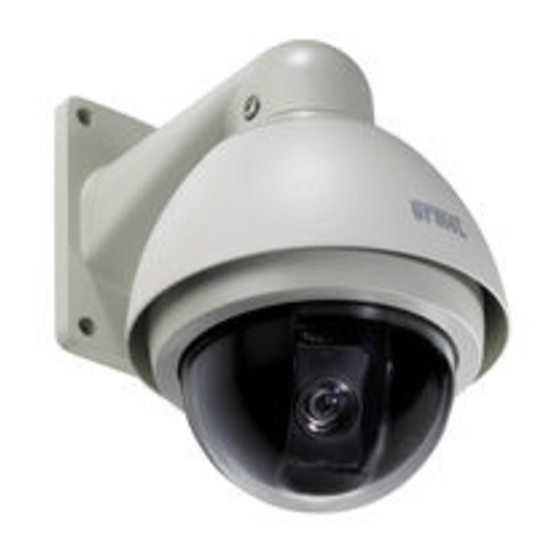
Minidome p/t/z thera 4
Vorschau ausblenden Andere Handbücher für 1092:

Werbung

Verfügbare Sprachen
  • DE

Verfügbare Sprachen

  • DEUTSCH, seite 81
-+
DS1092-041C
MINIDOME P/T/Z THERA 4
THERA 4 MINIDOME P/T/Z
MINIDOMO THERA 4
Sch./Ref./Réf./Typ 1092/601
MANUALE D'USO
INSTRUCTION MANUAL
MANUEL UTILISATEUR
BEDIENUNGSANLEITUNG
MANUAL DE INSTRUCCIONES
Mod.
1092

Werbung

Inhaltsverzeichnis
loading

Inhaltszusammenfassung für urmet domus 1092

  • Seite 1 Mod. 1092 DS1092-041C MINIDOME P/T/Z THERA 4 THERA 4 MINIDOME P/T/Z THERA 4 MINIDOME P/T/Z THERA 4 MINIDOME P/T/Z MINIDOMO THERA 4 Sch./Ref./Réf./Typ 1092/601 MANUALE D’USO INSTRUCTION MANUAL MANUEL UTILISATEUR BEDIENUNGSANLEITUNG MANUAL DE INSTRUCCIONES...
  • Seite 2: Caratteristiche Tecniche

    Velocità di spostamento manuale verticale: ..................0~60°/s Velocità in preset: ............................. 80°/s Numero di preset: ............................64 Numero tour:..............................1 Numero track tour (Solo con uso della tastiera 1092/620): ................6 Protocollo:............................Pelco D/P Baud rate: ........................2400, 4800, 9600, 19200 Alimentazione: ............................24 Vac Consumo massimo:..........................10VA...
  • Seite 3: Contenuto Della Confezione

    CONTENUTO DELLA CONFEZIONE  N°1 Minidome P/T/Z THERA 4.  N°1 Staffa per installazione a parete.  N°1 Staffa per installazione a soffitto.  N°1 Confezione contenente viti di fissaggio, una ghiera filettata e relativa guarnizione di tenuta per il montaggio della staffa da parete e soffitto, un piccolo cacciavite per la regolazione dei dip-switch interni della dome.
  • Seite 4: Precauzioni Per La Sicurezza

    NORME D’INSTALLAZIONE  Evitare di puntare direttamente l’obiettivo contro il sole o contro luci intense, anche se la dome è spenta; il soggetto da riprendere non deve essere in controluce.  La presenza di alcuni tipi di luce (ad esempio fluorescente colorata) può sfalsare i colori. ...
  • Seite 5 INSTALLAZIONE A SOFFITTO  Prima d’iniziare l’installazione, assicurarsi che tutte le unità da collegare non siano alimentate.  Avvitare la staffa circolare ad una delle due estremità del tubo filettato di raccordo.  Bloccare le due parti utilizzando le due viti svasate in dotazione (Vite 1). ...
  • Seite 6  Avvitare la dome all’estremità del tubo di raccordo avendo cura di non fare ruotare il cavo per evitare torsioni che potrebbero danneggiarlo (per far ciò è necessario, una volta inserito il cavo nella morsettiera della dome, avvitare il tubo di raccordo alla dome facendolo ruotare mantenendo ferma la dome).
  • Seite 7: Installazione A Parete

    INSTALLAZIONE A PARETE  Prima d’iniziare l’installazione, assicurarsi che tutte le unità da collegare non siano alimentate.  Posizionare sulla staffa da parete l’anello di tenuta in gomma (oring), a corredo, nella apposita sede.  Inserire il cavo di collegamento della dome, in dotazione, all’interno della staffa fino a farlo fuoriuscire dalla parte opposta.
  • Seite 8  Bloccare la staffa alla dome utilizzando le tre viti con la rondella in gomma, a testa bombata a corredo avvitandole saldamente nei tre fori presenti ai lati della staffa (Vite 3).  Posizionare la dome nel punto prescelto della parete avendo cura di far passare il cavo attraverso l’asola situata nella staffa o praticare un ulteriore foro sulla parete in corrispondenza del cavo in uscita dalla staffa di diametro sufficiente al passaggio del cavo intestato).
  • Seite 9  Collegare i due fili della RS485 per mezzo di morsettiera o eseguendo una saldatura alla borchia della tastiera (Sch.1092/620) rispettando le polarità : ARANCIO + (positivo) - GIALLO – (negativo).  Collegare i due fili di alimentazione per mezzo di morsettiera o eseguendo una saldatura ai due fili dell’alimentatore fornito in dotazione (non è...
  • Seite 10: Utilizzo Del Menu

    UTILIZZO DEL MENU La minidome THERA 4 utilizza un menu a più livelli che consente di abilitare/disabilitare o variare le impostazioni della telecamera (Modulo 200M). Per accedere al menu principale è necessario, a dome accesa e funzionante, premere in sequenza i tasti CALL –...
  • Seite 11 Opzione Valore Spiegazione Questa opzione consente di selezionare i parametri FOCUS relativi al funzionamento zoom della dome. Questa opzione consente di eseguire le regolazioni EXPOSURE relative alla telecamera. Questa opzione consente di attivare specifiche SPECIAL funzioni alla telecamera. Questa funzione consente di ripristinare tutte le variazioni eseguite dall’utente riportando la dome RESET allo stato iniziale.
  • Seite 12 WHITE BAL – BILANCIAMENTO DEL BIANCO Questa funzione consente di selezionare la modalità del bilanciamento del bianco. Selezionando questa voce di menu è possibile scegliere fra le opzioni MANUAL, AWC-SET e ATW. Opzione Valore Spiegazione Questa opzione consente di regolare manualmente MANUAL RED ÷...
  • Seite 13 Per mezzo dei tasti “freccia” è possibile variare l’indicazione OUTDOOR (per esterni) in INDOOR (per interni ). Premere CLOSE per tornare al menu precedente. Selezionare END e premere CLOSE per tornare al menu precedente. BACKLIGHT – BLC – COMPENSAZIONE CONTROLUCE Un oggetto inquadrato con forte luce proveniente da dietro solitamente appare scuro e poco visibile rispetto al resto dell’immagine.
  • Seite 14 Opzione Valore Spiegazione La funzione esegue l’inizializzazione dell’ottica LENS INIT della telecamera. Consente di uscire dal sottomenu. MODE Selezionando MODE è possibile scegliere fra le opzioni MANUAL (manuale), AUTO (automatica) e ONE- PUSH (una pressione). Selezionando MANUAL e premendo OPEN si accede al seguente sottomenu: ZOOM/FOCUS POS SETUP :TELE :WIDE...
  • Seite 15 ZOOM/FOCUS POS SETUP :TELE :WIDE :NEAR :FAR Press SET to Return Utilizzando I tasti “FOCUS” e “ZOOM” è possibile eseguire le regolazioni desiderate. TELE (avvicina l’immagine); WIDE (allarga l’immagine); NEAR (vicino); FAR (lontano). Premere CLOSE per tornare al menu precedente. Selezionare END e premere CLOSE per tornare al menu precedente.
  • Seite 16 EXPOSURE– ESPOSIZIONE Questa funzione consente di variare le funzioni relative all’ottica della dome. Selezionando questa voce di menu e premendo il tasto OPEN si accede al seguente sottomenu: EXPOSURE SETUP BRIGHTNESS 41 ■■■■■■■█■■■ IRIS MANUAL SHUTTER MANUAL NORMAL SSNR HIGH SENS-UP Opzione Valore...
  • Seite 17 Selezionando IRIS VAL e premendo i tasti “freccia” è possibile variare la percentuale di apertura dell’iride della dome scegliere fra i valori compresi tra 1 a 100. Questa regolazione deve essere variata solo in condizioni estreme di utilizzo della dome. Per tutte le altre applicazioni si consiglia di utilizzare la modalità...
  • Seite 18 SENS-UP (DSS) – VARIAZIONE DELLA SENSIBILITA’ DELLA TELECAMERA IN FUNZIONE DELLA VARIAZIONE DI LUCE Questo dispositivo consente di effettuare riprese di scene in condizioni di scarsa luminosità. Alla graduale diminuzione della luminosità, corrisponde una diminuzione dei frame per secondo (numero di immagini/secondo) aumentando la sensibilità...
  • Seite 19 Opzione Valore Spiegazione FUNZIONE ATTUALMENTE NON DISPONIBILE USER PRESET ON ÷OFF FUNZIONE ATTUALMENTE NON DISPONIBILE PRIVACY ON ÷ OFF Consente di selezionare la modalità di variazione del funzionamento della telecamera in funzione COLOR ÷ B/W ÷ DAY/NIGHT AUTO1 ÷ AUTO2 ÷ delle condizioni di utilizzo.
  • Seite 20 IMAGE ADJ Selezionando IMAGE ADJ e premendo OPEN si accede al seguente sottomenu: IMAGE SETUP FREEZE H-REV V-REV SHARPNESS COLOR GAIN 56 ■■■■■■■█■■■ Opzione Valore Spiegazione Selezionando ON viene attivata la funzione di FREEZE ON ÷OFF “Fermo Immagine”. Consente di capovolgere l’immagine H-REV (MIRROR) ON ÷...
  • Seite 21: Impostazione Dell'indirizzo

    IMPOSTAZIONE DELLA DOME Per eseguire le impostazioni di indirizzo,di baud rate e protocollo di comunicazione è necessario rimuovere la cupola estera e la cupola interna della dome procedendo nel seguente modo: Ruotare in senso antiorario la cupola esterna per circa ¼ di giro per sbloccarla dalla sede. Ruotare in senso antiorario la cupola interna per circa ¼...
  • Seite 22: Impostazioni Di Baud Rate

    IMPOSTAZIONI DI BAUD RATE E’ possibile selezionare la velocità comunicazione (baud rate) variando la configurazione dei dipswitch (numero 1 e 2) situati sul PCB della dome, seguendo le posizioni indicate: BAUD RATE PROTOCOLLO 9600 19200 2400 4800 IMPOSTAZIONI DI PROTOCOLLO DI COMUNICAZIONE E’...
  • Seite 23 DESCRIZIONE DELLE FUNZIONI CON USO DELLA TASTIERA SCH.1092/620  64 preset: Questa funzione consente di memorizzare fino ad un massimo di 50 inquadrature fisse da utilizzare nelle funzioni di seguito descritte. I rimanenti 14 preset sono utilizzati dalla dome per l’utilizzo delle funzioni e non possono essere variate.Tutte le inquadrature memorizzate (Preset) non...
  • Seite 24 IMPOSTAZIONE E ATTIVAZIONE DELLE FUNZIONI Nota Bene : Per l’identificazione dei tasti vedere il manuale a corredo della tastiera. Spostare l’inquadratura manualmente Per spostare l’inquadratura manualmente in un punto voluto, agire sui pulsanti “UP”, “DOWN”, “LEFT” e “RIGHT” della tastiera. E’ possibile variare la velocità di spostamento scegliendo tra 10 possibilità premendo i tasti numerici compresi tra 0 e 9 prima di premere i tasti di direzione.
  • Seite 25 Proseguire nel memorizzare i preset da inserire nel tour, fino a un massimo di 16, seguendo i passi precedentemente descritti. Una volta inseriti tutti i preset desiderati e i parametri richiesti, terminare l’operazione premendo il tasto “ON”. Riassumendo: N° tour (da 1 a 6) + “TOUR” + “ON” DOWN N°...
  • Seite 26: Pulizia Del Dispositivo

    Repeat Last). Premere da tastiera “PRESET+102+ON” per disabilitare la funzione. Nota Bene: Utilizzando tastiere diverse dalla Sch.1092/620 o DVR è possibile accedere alle funzioni della dome precedentemente descritte ad esclusione dei sei gruppi di track tour programmabili.
  • Seite 27 DIAGNOSTICA PROBLEMI POSSIBILI CAUSE SOLUZIONI Errore nella progettazione del Verificare Dopo l’accensione, nessun cablaggio movimento e nessuna immagine Errore nel collegamento dei Correggere cavi elettrici Errore meccanico Verificare Anomala auto diagnosi, Dome inclinata Riposizionare nel modo corretto immagine normale con rumore di motore Sostituire con appropriata fornitura di Alimentazione a bassa...
  • Seite 28: Technical Specifications

    Manual tilting speed:..........................0~60°/s Preset speed: ............................80°/s Number of presettings: ..........................64 Number of tours:..............................1 Number of track tours (with 1092/620 control panel only): ................6 Protocol: ............................Pelco D/P Baud rate: ........................2400, 4800, 9600, 19200 Power: ..............................24 Vac Maximum consumption:..........................10VA Working temperature: ........................
  • Seite 29: Contents Of The Box

    CONTENTS OF THE BOX  1 Mini Dome P/T/Z THERA 4  1 wall mounting bracket  1 ceiling mounting bracket  1 box containing fastening screws, a threaded ring and seal for mounting the bracket on wall or ceiling, a small screw driver for adjusting the internal dome dip switches ...
  • Seite 30: Installation Instructions

    INSTALLATION INSTRUCTIONS  Avoid pointing the lens directly towards the sun or intense sources of light, even when the dome is off. The subject must not be backlit.  Some lighting systems (e.g. coloured fluorescent lights) may distort the colours. ...
  • Seite 31: Ceiling Installation

    CEILING INSTALLATION  Make sure that no units are powered before starting the installation procedure.  Secure the circular bracket to one of the two ends of the threaded union tube.  Block the two parts using the two flared screws provide (screw 1). ...
  • Seite 32  Fasten the dome to the end of the union tube being careful not to turn the tube to prevent twisting and damage (in order to do this, plug the wire into the dome terminal board, fasten the union tube to the dome making it turn while holding the dome still).
  • Seite 33 WALL FITTING  Make sure that no units are powered before starting the installation procedure.  Position the rubber o-ring (included) on the wall bracket in the specific seat.  Insert the dome connection wire (included) in the bracket until it protrudes from the opposite side. ...
  • Seite 34  Secure the bracket to the dome using the round-headed screws with rubber washer (included). Fasten tightly in the three holes on the sides of the bracket (screw 3).  Position the dome in the chosen point on the wall making the wire pass through the slot located in the bracket or make a further hole on the wall at the outlet wire from the bracket of diameter sufficient to let the connected wire through.
  • Seite 35 Connect the second end of the wire to the video device by means of the male BNC connector.  Connect the two wires of the RS485 by means of the terminal board or by welding to the control panel socket (Ref. 1092/620) respecting the following polarities: ORANGE + (positive) - YELLOW – (negative). ...
  • Seite 36 USING THE MENU The THERA 4 mini dome uses a multiple level menu for enabling/disabling or adjusting the camera settings (200M module). To access the main menu press CALL – 57 – ON in sequence with the dome on and running. Important note: The menu will automatically disappear after approximately three minutes if no functions are activated using the control panel.
  • Seite 37 Option Value Explanation This option is used to select the dome zoom FOCUS parameters. This option is used to adjust the camera. EXPOSURE This option is used to activate specific camera SPECIAL functions. This function is used reset the default settings of RESET the dome.
  • Seite 38 WHITE BAL This option is used to select white balance mode. Options of this menu item are MANUAL, AWC-SET and ATW. Option Value Explanation This option is used to manually adjust white MANUAL RED - BLUE balance. FUNCTION NOT CURRENTLY AVAILABLE AWC-SET This is allowed to select the predetermined white balance settings for the camera to work outdoor or...
  • Seite 39 Press the arrow buttons to switch from OUTDOOR to INDOOR. Press CLOSE to go back to the previous menu. Select END and press CLOSE to go back to the previous menu. BACKLIGHT – BLC Subjects will appear dark and hardly visible if lit by a strong light from the back. The BLC function avoids this problem and provides good compensation.
  • Seite 40 Option Value Explanation This function is used to initialise the camera lens. LENS INIT This is used to quit the submenu. MODE MODE options are MANUAL, AUTO (automatic) and ONE-PUSH. Select MANUAL and press OPEN to access the following submenu: ZOOM/FOCUS POS SETUP :TELE :WIDE...
  • Seite 41 ZOOM/FOCUS POS SETUP :TELE :WIDE :NEAR :FAR Press SET to Return Use the “FOCUS” and “ZOOM” buttons to make the required settings: TELE (zoom in); WIDE (zoom out); NEAR; FAR. Press CLOSE to go back to the previous menu. Select END and press CLOSE to go back to the previous menu. ZOOM SPEED Select ZOOM SPEED and then select the options: FAST and SLOW.
  • Seite 42 EXPOSURE This function is used to adjust the dome lens functions. Select this menu item and press OPEN to access the following submenu: EXPOSURE SETUP BRIGHTNESS 41 ■■■■■■■█■■■ IRIS MANUAL SHUTTER MANUAL NORMAL SSNR HIGH SENS-UP Option Value Explanation This setting is used to adjust the brightness of the BRIGHTNESS 0 - 100 image.
  • Seite 43 Select IRIS VAL and press the arrow buttons to vary the opening percentage of the dome iris. Values from 1 to 100 can be selected. This setting must be varied only in extreme conditions of use of the dome. AUTO mode is recommended for all applications.
  • Seite 44 SENS-UP (DSS) – FOR ADJUSTING CAMERA SENSITIVITY ACCORDING TO LIGHT VARIATIONS This device is used to adjust shooting in poor light conditions. The frame per second rate decreases as the light gradually decreases, thus increasing camera sensitivity. Select SENS-UP and then the options: AUTO (automatic) and OFF. Select AUTO and press OPEN to access the following submenu: SENS-UP LIMIT SETUP LIMIT...
  • Seite 45 Option Value Explanation FUNCTION NOT CURRENTLY AVAILABLE USER PRESET ON - OFF FUNCTION NOT CURRENTLY AVAILABLE PRIVACY ON - OFF COLOR - B/W - This is used to adjust the camera operating mode DAY/NIGHT AUTO1 - AUTO2 - according to conditions of use. This indicates that synchronisation is internal and SYNC cannot be varied.
  • Seite 46 IMAGE ADJ Select IMAGE ADJ and press OPEN to access the following submenu: IMAGE SETUP FREEZE H-REV V-REV SHARPNESS COLOR GAIN 56 ■■■■■■■█■■■ Option Value Explanation Select ON to activate freeze function. FREEZE ON - OFF This is used to tip the image horizontally. H-REV (MIRROR) ON - OFF This is used to tip the image vertically.
  • Seite 47: Dome Settings

    DOME SETTINGS The external dome and the internal dome must be removed in the following manner to set the address, the baud rate and the communication protocol: Turn the external dome anticlockwise by approximately ¼ a turn to release it from its seat. Turn the internal dome anticlockwise by approximately ¼...
  • Seite 48: Setting The Baud Rate

    SETTING THE BAUD RATE The communication speed (baud rate) can be selected by varying the configuration of the dip switches (number 1 and 2) on the PCB of the dome as shown: BAUD RATE PROTOCOL 9600 19200 2400 4800 SETTINGS THE COMMUNICATION PROTOCOL The communication protocol can be selected by varying the configuration of the dip switches (number 3 and 4) on the PCB of the dome as shown: BAUD RATE...
  • Seite 49 DESCRIPTION OF FUNCTIONS AVAILABLE IN COMBINATION WITH CONTROL PANEL REF. 1092/620  64 preset positions: This function is used to store up to 50 presetting fixed positions for use with the functions described below. The remaining 14 preset positions are used by the dome for special functions and cannot be changed.
  • Seite 50 FUNCTION SETTING AND ACTIVATION Important note: Refer to the control panel manual for identification of the buttons. Manually moving the frame Press “UP”, “DOWN”, “LEFT” and “RIGHT” on the control panel to move the frame manually to a required point. The speed can be changed by choosing between 10 possible positions and pressing the alphanumeric buttons between 0 and 9 before pressing the direction buttons.
  • Seite 51 Proceed by storing preset positions to be included in the tour, up to 16, following the previously described steps. After entering all the required presettings and parameters, press “ON” to end the operation. In brief: Tour n. (from 1 to 6) + “TOUR” + “ON” DOWN Preset n.
  • Seite 52: Cleaning The Device

    Important note: The previously described dome functions, except for the six programmable track tours may be used by employ different control panels other than Ref.1092/620 or DVR. Refer to the instruction of each product for how to access the functions.
  • Seite 53: Troubleshooting

    TROUBLESHOOTING PROBLEMS POSSIBLE CAUSES SOLUTIONS Wiring design error. Check. There is no movement and no picture after having been Electrical wiring connection switched on error. Correct. Mechanical error. Check. Self-test is not OK. The Inclined dome. Reposition correctly. picture is normal but the motor is noisy.
  • Seite 54: Caracteristiques Techniques

    Vitesse en preset :............................ 80°/s Nombre de preset :............................64 Nombre de tours :............................1 Nombre de track tours (uniquement avec le clavier 1092/620) :..............6 Protocole : ............................Pelco D/P Débit en bauds : ......................2400, 4800, 9600, 19200 Alimentation :............................24 Vca Consommation maximum :........................10VA...
  • Seite 55: Contenu De L'emballage

    CONTENU DE L’EMBALLAGE  N°1 Minidôme P/T/Z THERA 4.  N°1 étrier pour l’installation murale.  N°1 étrier pour l’installation au plafond.  N°1 kit contenant des vis de fixation, une bague filetée et son joint d’étanchéité pour le montage de l’étrier au mur/plafond, un petit tournevis pour le réglage des commutateurs situés à...
  • Seite 56: Normes D'installation

    NORMES D’INSTALLATION  Eviter de diriger directement l’objectif vers le soleil ou des sources lumineuses intenses, et ce même si le dôme est éteinte ; le sujet à filmer ne doit pas être à contre-jour.  La présence de certains types de lumière (par exemple, fluorescente colorée) peut altérer les couleurs.
  • Seite 57: Installation Au Plafond

    INSTALLATION AU PLAFOND  Avant de procéder à l’installation, s’assurer que toutes les unités à brancher sont hors tension.  Visser l’étrier rond sur l’une des deux extrémités du tuyau fileté de raccordement.  Bloquer les deux parties en utilisant les deux vis évasées livrées de série (Vis 1). ...
  • Seite 58  Visser le dôme sur l’extrémité du tuyau de raccordement, en veillant à ne pas faire tourner le câble pour éviter toute torsion susceptible de l’endommager (pour ce faire, une fois le câble branché sur le bornier du dôme, visser le tuyau de raccordement sur celle-ci, en le faisant tourner tout en maintenant la caméra).
  • Seite 59: Installation Murale

    INSTALLATION MURALE  Avant de procéder à l’installation, s’assurer que toutes les unités à brancher sont hors tension.  Sur l’étrier mural, mettre correctement en place la bague d’étanchéité en caoutchouc (joint torique), livrée de série.  Introduire le câble de connexion du dôme (livré de série) à l’intérieur de l’étrier, jusqu’à ce qu’il sorte par le côté...
  • Seite 60  Fixer l’étrier au dôme, en utilisant les deux vis à tête bombée, munies de rondelle en caoutchouc (livrées de série), en les vissant fermement dans les deux orifices prévus de part et d’autre de l’étrier (Vis 3).  Positionner le dôme à l’endroit choisi sur le mur, en veillant à faire passer le câble à travers la boutonnière située sur l’étrier ;...
  • Seite 61 Brancher l’autre extrémité du câble sur le dispositif vidéo, via le connecteur BNC mâle.  Brancher les deux fils de la RS485 via le bornier ou par le biais d’une soudure sur la boîte de connexion du clavier (Réf. 1092/620), en respectant les polarités : ORANGE + (positif) - JAUNE – (négatif). ...
  • Seite 62 CLAVIER BOITE DE CONNEXION Insérer la résistance Figure 4: CONFIGURATION EN CASCADE N.B. : La somme des longueurs des différents tronçons de la ligne RS485 ne doit jamais dépasser 1200 m. CLAVIER BOITE DE CONNEXION Insérer la résistance Insérer la résistance Figure 3: CONFIGURATION EN ETOILE N.B.
  • Seite 63: Utilisation Du Menu

    UTILISATION DU MENU Le minidôme THERA 4 utilise un menu à plusieurs niveaux, permettant d’habiliter/exclure ou de modifier les paramètres de la caméra (Module 200M). Pour accéder au menu principal, il est nécessaire d’appuyer dans l’ordre sur les touches CALL – 57 – ON, le dôme allumée et en état de marche.
  • Seite 64 Option Valeur Explication Cette option permet de sélectionner les paramètres ayant trait au fonctionnement zoom du FOCUS dôme. Cette option permet d’effectuer les réglages de la EXPOSURE caméra. Cette option permet d’activer des fonctions SPECIAL spécifiques de la caméra. Cette option permet de rétablir toutes les modifications apportées par l’utilisateur, en RESET ramenant le dôme à...
  • Seite 65 WHITE BAL – EQUILIBRAGE DU BLANC Cette fonction permet de sélectionner la modalité d’équilibrage du blanc. En sélectionnant cette rubrique du menu, il est possible de choisir parmi les options MANUAL, AWC-SET et ATW. Option Valeur Explication Cette option permet de régler manuellement MANUAL RED ÷...
  • Seite 66 A l’aide des touches « flèches », il est possible de modifier le paramètre OUTDOOR (en extérieur) en INDOOR (en intérieur). Appuyer sur CLOSE pour revenir au menu précédent. Sélectionner END et appuyer sur CLOSE pour revenir au menu précédent. BACKLIGHT –...
  • Seite 67 Option Valeur Explication Cette fonction assure l’initialisation optique de la LENS INIT caméra. Cette option permet de quitter le sous-menu. MODE En sélectionnant MODE, il est possible de choisir parmi les options MANUAL (manuelle), AUTO (automatique) et ONE-PUSH (une pression). En sélectionnant MANUAL et en appuyant sur OPEN, l’on accède au sous-menu suivant : ZOOM/FOCUS POS SETUP :TELE...
  • Seite 68 ZOOM/FOCUS POS SETUP :TELE :WIDE :NEAR :FAR Press SET to Return A l’aide des touches « FOCUS » et « ZOOM », il es possible d’accomplir les réglages désirés : TELE (rapprochement de l’image) ; WIDE (élargissement de l’image) ; NEAR (près) ; FAR (loin). Appuyer sur CLOSE pour revenir au menu précédent.
  • Seite 69 EXPOSURE – EXPOSITION Cette fonction permet de modifier les paramètres optiques du dôme. En sélectionnant cette rubrique du menu et en appuyant sur la touche OPEN, l’on accède au sous-menu suivant : EXPOSURE SETUP BRIGHTNESS 41 ■■■■■■■█■■■ IRIS MANUAL SHUTTER MANUAL NORMAL SSNR...
  • Seite 70 En sélectionnant IRIS VAL et en appuyant sur les touches « flèches », il est possible de modifier le taux d’ouverture de l’iris du dôme, en choisissant une valeur comprise entre 1 et 100. Ce réglage ne doit être modifié qu’en cas d’utilisation du dôme dans des conditions extrêmes. Pour toutes les autres applications, il est conseillé...
  • Seite 71 SENS-UP (DSS) – VARIATION DE LA SENSIBILITE DE LA CAMERA EN FONCTION DE LA VARIATION DE LUMIERE Ce dispositif permet de filmer dans des conditions de faible luminosité. Au fur et à mesure que la luminosité diminue, les trames par seconde (nombre d’images/seconde) diminuent, de manière à augmenter la sensibilité...
  • Seite 72 Option Valeur Explication FONCTION ACTUELLEMENT NON DISPONIBLE USER PRESET ON ÷OFF FONCTION ACTUELLEMENT NON DISPONIBLE PRIVACY ON ÷ OFF Cette option permet de sélectionner la modalité de COLOR ÷ B/W ÷ variation du fonctionnement de la caméra selon ses DAY/NIGHT AUTO1 ÷...
  • Seite 73 IMAGE ADJ En sélectionnant IMAGE ADJ et en appuyant sur OPEN, l’on accède au sous-menu suivant : IMAGE SETUP FREEZE H-REV V-REV SHARPNESS COLOR GAIN 56 ■■■■■■■█■■■ Option Valeur Explication En sélectionnant ON, la fonction « Arrêt sur FREEZE ON ÷OFF image »...
  • Seite 74: Programmation Du Dôme

    PROGRAMMATION DU DÔME Pour définir les paramètres d’adresse, de débit en bauds et de protocole de communication, il est nécessaire de déposer les dômes extérieur et intérieur du dôme, en procédant comme suit : Tourner le dôme extérieur d’environ ¼ de tour dans le sens inverse à celui des aiguilles d’une montre, afin de le débloquer.
  • Seite 75: Programmation Du Debit En Bauds

    PROGRAMMATION DU DEBIT EN BAUDS Il est possible de sélectionner la vitesse de communication (débit en bauds), en modifiant la configuration des commutateurs (n. 1 et 2) situés sur le PCB de la caméra, selon les positions indiquées : DEBIT EN BAUDS PROTOCOLE 9600 19200...
  • Seite 76 DESCRIPTION DES FONCTIONS ACCESSIBLES A L’AIDE DU CLAVIER REF. 1092/620  64 presets : Cette fonction permet de mémoriser jusqu’à un maximum de 50 prises de vue fixes, à utiliser pour les fonctions décrites ci-après. Les 14 presets restants sont utilisés par le dôme pour les fonctions et ils ne peuvent être modifiés.
  • Seite 77 PROGRAMMATION ET ACTIVATION DES FONCTIONS N.B. : Pour l’identification des touches, se reporter au manuel livré avec le clavier. Déplacer manuellement la prise de vue Pour déplacer manuellement la prise de vue dans un endroit donné, appuyer sur les touches « UP », «...
  • Seite 78 Mémoriser tous les presets à inclure dans le tour (maximum 16), en suivant la procédure que l’on vient de décrire. Une fois que tous les presets désirés et les paramètres requis ont été programmés, terminer l’opération en appuyant sur la touche « ON ». En récapitulant : N.
  • Seite 79: Nettoyage Du Dispositif

    Appuyer sur « PRESET+102+ON » pour exclure la fonction. N.B. : Si l’on utilise des claviers autres que le modèle Réf. 1092/620 ou DVR, il sera possible d’accéder aux fonctions du dôme décrites ci-dessus, à l’exception des six groupes de track tours programmables.
  • Seite 80 DIAGNOSTIC PROBLEMES CAUSES POSSIBLES SOLUTIONS Erreur de conception du Vérifier. Après la mise sous tension, il câblage. n’y a aucun mouvement et aucune image. Erreur de connexion des Rectifier. câbles électriques. Vérifier. Erreur mécanique. Autodiagnostic anormal, Repositionner correctement le dôme. Dôme inclinée.
  • Seite 81: Technische Eigenschaften

    DEUTSCH VORSICHTSMASSNAHMEN  Nach dem Auspacken des Geräts muss sichergestellt werde, dass es sich in einwandfreiem Zustand befindet.  Ausführen jeglicher Reinigungs- Wartungsarbeiten, Gerät Stromversorgungsnetz trennen. Für die Reinigung des Geräts keine Sprays verwenden.  Überprüfen, ob die Betriebstemperatur sich innerhalb der angezeigten Grenzwerte befindet und die Umgebung nicht besonders feucht ist.
  • Seite 82: Inhalt Der Verpackung

    INHALT DER VERPACKUNG  1 Minidome P/T/Z THERA 4  1 Wandhalterung  1 kreisförmige Halterung für die Deckenmontage  1 Gewindering  Eine Packung mit Befestigungsschrauben, einem Dichtungsring für die Decken- oder Wandmontage, ein schmaler Schraubendreher zum Einstellen der internen DIP-Schalter ...
  • Seite 83: Installationsbestimmungen

    INSTALLATIONSBESTIMMUNGEN  Vermeiden Sie es, das Objektiv gegen die Sonne oder intensive Lichteinstrahlung zu richten, auch bei ausgeschaltetem Dome. Der aufzunehmende Gegenstand darf sich nicht im Gegenlicht befinden.  Einige Lichtarten (wie z. B. fluoreszierendes farbiges Licht) können die Farben verfälschen. ...
  • Seite 84 DECKENMONTAGE  Vor der Installation sicherstellen, dass alle anzuschließenden Einheiten von der Versorgungs getrennt sind.  Die kreisförmige Halterung mit einem der beiden Enden des Anschlussrohres mit dem Gewinde verschrauben.  Die beiden Teile unter Verwendung von zwei in der Lieferung enthaltenen Schrauben befestigen (Schraube 1).
  • Seite 85  Das Dome-Gehäuse mit dem Ende des Anschlussrohrs verschrauben und dabei darauf achten das Kabel nicht zu drehen, um Verdrehungen zu vermeiden, die dieses beschädigen könnten (hierzu ist es erforderlich, sobald das Kabel in den Steckkontaktes der Dome eingeführt ist, das Anschlussrohr mit dem Dome-Gehäuse zu verschrauben, indem es gedreht wird, während das Dome-Gehäuse festgehalten wird).
  • Seite 86 WANDMONTAGE  Vor der Installation sicherstellen, dass alle anzuschließenden Einheiten von der Versorgungs getrennt sind.  Positionierung des im Lieferumfang enthaltenen Dichtungsrings in der dafür vorgesehen Aussparung des Wandhalters.  Das im Lieferumfang enthaltene Anschlusskabel in die zentrale Öffnung der Wandhalterung einführen, um es am Ende des Rohrs austreten zu lassen.
  • Seite 87  Das Anschlussrohr am Dome-Gehäuse mit den im Lieferumfang enthaltenen Schrauben inklusiv Dichtungsring befestigen (Schraube 2).  Den Dome an der zuvor ausgewählten Stelle an der Wand montieren und dabei darauf achten, das Anschlusskabel über die Aussparung oder durch ein entsprechend größeres Loch in der Wand zu führen.
  • Seite 88  Anschließen des anderen Endes des Anschlusskabels mittels des BNC-Steckers an ein Videogerät.  Die beiden Adern des RS485 Datenbus mit dem Steuerpult (z. B Typ 1092/620) verbinden, hierbei die Polarität beachten: ORANGE + (Positiv) / GELB – (Negativ). ...
  • Seite 89: Einstellung Der Betriebsarten Über Das Menü

    Die THERA 4 Mini Dome nutzt ein Mehrfach-Bereichsmenü für die Aktivierung/Deaktivierung oder justieren von Kameraeinstellungen (200M Modul). Um auf das Menü zugreifen zu können, muss am Steuerpult (z. B. Typ 1092/620) CALL – 57 – ON in Abhängigkeit dass die Dome-Kamera eingeschaltet ist und läuft.
  • Seite 90 Option Wert Erklärung Auswahl zum Ändern der Zoom- und FOCUS Fokusfunktionen des Domes. Auswahl zur Justierung des Kamera-Objektivs. EXPOSURE Auswahl für spezifische Kamerafunktionen. SPECIAL Rücksetzen der Funktionen in die RESET Werkseinstellungen. Verlassen der Menüebene. BESCHREIBUNG MENÜPUNKTE CAM TITLE Diese Funktion ist für die Benennung der Kamera und Anzeige der Benennung auf dem Monitor an einer vom Benutzer definierten Stelle.
  • Seite 91 WHITE BAL Diese Funktion erlaubt die Auswahl des Weißabgleich-Modus. Optionen des Menüpunkts sind MANUAL, AWC-SET und ATW-MODE. Option Wert Erklärung Option zur manuellen Bestimmung des MANUAL RED - BLUE Weißabgleichs. FUNKTION NICHT VERFÜGBAR AWC-SET Diese Funktion bestimmt nach vorher eingestelltem Weißabgleich den Einsatzbereich Innen oder ATW MODE OUTDOOR - INDOOR...
  • Seite 92 BACKLIGHT – BLC Ein ausgewählter Gegenstand mit starkem von hinten kommenden Licht erscheint normalweise Dunkel und im Vergleich zum Rest des Bildes schlecht sichtbar. Die BLC-Funktion hat die Funktion diesem Problem abzuhelfen und einen guten Ausgleich zu erzielen. Optionen zur Auswahl des Menüpunkts sind: OFF, LOW, MIDDLE und HIGH. FOCUS –...
  • Seite 93 MODE Optionen zur Auswahl des Menüpunkts sind MANUAL, AUTO (automatic) and ONE-PUSH. Durch Auswahl MANUAL und Betätigung der Taste OPEN erfolgt der Zugang zum Menüpunkt. ZOOM/FOCUS POS SETUP :TELE :WIDE :NEAR :FAR Press SET to Return Durch Nutzung der Tasten FOCUS und ZOOM können die erforderlichen Einstellungen ausgeführt werden: TELE (ranzoomen);...
  • Seite 94 Auswahl ONE-PUSH (Der Focus kann über Tastendruck manuell eingestellt werden, sobald die Zoomfunktion ausgeführt wird, stellt sich der Focus wieder automatisch ein) und Betätigung der Taste OPEN erfolgt der Zugang zum Menüpunkt: ZOOM/FOCUS POS SETUP :TELE :WIDE :NEAR :FAR Press SET to Return Durch Nutzung der Tasten FOCUS und ZOOM können die erforderlichen Einstellungen ausgeführt werden: TELE (ranzoomen);...
  • Seite 95 EXPOSURE Diese Funktion erlaubt die Einstellungen der Belichtungsfunktionen des Kamera-Objektivs. Durch Auswahl dieses Menüpunkts und Betätigung der Taste OPEN erfolgt der Zugang. EXPOSURE SETUP BRIGHTNESS 41 ■■■■■■■█■■■ IRIS MANUAL SHUTTER MANUAL NORMAL SSNR HIGH SENS-UP Option Wert Erklärung Auswahl zur Einstellung der Helligkeit des BRIGHTNESS 0 - 100 dargestellten Videobildes.
  • Seite 96 Auswahl IRIS VAL und durch betätigen der Pfeiltasten kann der Blendenwert verändert werden. Werte von 1 bis 100 können ausgewählt werden. Diese Einstellung sollte nur bei stark variierenden Lichtverhältnissen eingestellt werden. Der Modus AUTO wird für diese Anwendung empfohlen. Über die Auswahl END und betätigen der Taste CLOSE gelangt man zurück ins Hauptmenü. SHUTTER Auswahl SHUTTER und die Optionen hier: MANUAL, A.FLK and ESC.
  • Seite 97 SENS-UP (DSS) – ZUR EINSTELLUNG DER KAMERA-EMPFINDLICHKEIT ENTSPRECHEND DEN LICHTERVERHÄLTNISSEN Diese Funktion erlaubt die Darstellung des Videobildes auch sehr schlechten Lichtverhältnissen. Verringerung der Bildrate in Abhängigkeit der Helligkeit, dadurch auch Verringerung der Kamera- Empfindlichkeit. Auswahl SENS-UP und die Optionen hier: AUTO (Automatisch) and OFF. Durch Auswahl AUTO und Betätigung der Taste OPEN erfolgt der Zugang zum Menüpunkt.
  • Seite 98 Option Wert Erklärung FUNKTION NICHT VERFÜGBAR USER PRESET ON - OFF FUNKTION NICHT VERFÜGBAR PRIVACY ON - OFF COLOR - B/W - Auswahl der Betriebsart der Kamera in DAY/NIGHT AUTO1 - AUTO2 - Abhängigkeit der Nutzung. Diese Funktion kennzeichnet eine interne Synchronisation und diese kann nicht verändert SYNC werden.
  • Seite 99 IMAGE ADJ Durch Auswahl IMAGE ADJ und Betätigung der Taste OPEN erfolgt der Zugang zum Menüpunkt. IMAGE SETUP FREEZE H-REV V-REV SHARPNESS COLOR GAIN 56 ■■■■■■■█■■■ Option Wert Erklärung Auswahl ON zur Aktivierung des Standbilds. FREEZE ON - OFF Auswahl zum Kippen des Bildes horizontal. H-REV (MIRROR) ON - OFF Auswahl zum Kippen des Bildes vertikal.
  • Seite 100: Einstellungen Dome

    EINSTELLUNGEN DOME Die externe und interne Domekuppel muss wie folgt entfernt werden, damit die Einstellungen der Baud Rate, des Protokolls und der Adresse ausgeführt werden können: Die externe Kuppel der Dome entfernen, indem diese entgegen des Uhrzeigersinns um ca. eine Viertel Umdrehung gelöst wird.
  • Seite 101: Einstellung Der Baud Rate

    EINSTELLUNG DER BAUD RATE Die Übertragungsgeschwindigkeit (Baud rate) kann ausgewählt werden, indem die Konfiguration der Dipschalter (Nummer 1 und 2) auf dem PCB der Dome unter Einhaltung der folgenden Positionen verändert wird: BAUD RATE PROTOKOLL 19200 2400 4800 9600 EINSTELLUNG DES KOMMUNIKATIONSPROTOKOLLS Das Kommunikationsprotokoll kann ausgewählt werden, indem die Konfiguration der Dipschalter (Nummer 3 und 4) auf dem PCB der Dome unter Einhaltung der folgenden Positionen verändert wird: BAUD RATE...
  • Seite 102: Beschreibung Der Funktion Unter Einsatz Der Tastatur Typ

    BESCHREIBUNG DER FUNKTION UNTER EINSATZ DER TASTATUR TYP 1092/620  64 Preset Funktionen: Diese Funktion gestattet die Speicherung einer Höchstzahl von 50 festen Bildausschnitten, die in dem Anschluss beschriebenen Funktionen verwendet werden können. Die restlichen 14 Presets werden vom Dome für spezielle Funktionen genutzt und können nicht verändert werden.
  • Seite 103: Eingabe Und Aktivierung Der Funktionen

    EINGABE UND AKTIVIERUNG DER FUNKTIONEN Beachten: Zur Identifizierung der Tasten sollte die im Lieferumfang der Tastatur enthaltene Anleitung zu Rate gezogen werden Manuelles Verschieben des Bildausschnitts Um den Bildausschnitt manuell an eine gewünschte Stelle zu verschieben, die Tasten “UP”, “DOWN”, “LEFT”...
  • Seite 104 Eingabe einer Track-Tour Im Modus Standby die numerische Taste (von 1 bis 6) betätigen, die der Tour entspricht die gespeichert werden soll. “TOUR” betätigen und die Taste “ON”. Auf dem Display erscheint “N – 01”. Dies ist ein Zähler der die Nummer des Presets darstellt, der eingeben wird. Anschließend die Taste “DOWN” betätigen. Das Display zeigt “P - - X”...
  • Seite 105 Wiederaufnahme der letzten Funktion). Um den Vorgang zu deaktivieren, auf der Tastatur “PRESET+102+ON” betätigen. Beachten: Durch Verwendung von anderen Tastaturen als der 1092/620 oder DVR´s kann auf die zuvor beschriebenen Funktionen zugegriffen werden, mit Ausnahme der sechs programmierbaren Track-Touren. Um darauf Zugriff zu erhalten, beziehen Sie sich auf die Gebrauchsanweisung eines jeden Produkts.
  • Seite 106: Reinigung Der Vorrichtung

    REINIGUNG DER VORRICHTUNG  Ein trockenes Tuch verwenden und leicht abreiben, um Staub oder Schmutz zu beseitigen.  Sollte der Schmutz mit einem trockenen Tuch nicht zu entfernen sein, den Vorgang mit einem mit neutralem Reinigungsmittel angefeuchteten Tuch ausführen.  Kein flüchtigen Flüssigkeiten wie Benzin, Alkohol.
  • Seite 107 DIAGNOSTIK PROBLEME MÖGLICHE URSACHEN LÖSUNGEN Fehler der Planung der Überprüfen. Verkabelung. Nach dem Einschalten keine Bewegung und kein Bild Fehler beim Anschluss der Korrigieren. Elektrokabel. Mechanischer Fehler. Überprüfen. Anormale Selbstdiagnose, Dome geneigt. Korrekte Neupositionierung. normales Bild mit Motorengeräusch Das Netzteil in der Nähe der Dome Geringe positionieren (optimale Position).
  • Seite 108: Especificaciones Técnicas

    Velocidad vertical manual:......................De 0 a 60°/s Velocidad entre presets:........................... 80°/s Número de presets: ............................64 Número de tours:.............................1 Número de tours programables (sólo con el teclado 1092/620): ..............6 Protocolo: ............................Pelco D/P Velocidad de transferencia (baudios): ..............2.400, 4.800, 9.600, 19.200 Alimentación eléctrica:.......................... 24 VAC Consumo máximo:...........................10 VA...
  • Seite 109: Contenido De La Caja

    CONTENIDO DE LA CAJA  1 Minidomo THERA 4  1 soporte de montaje en la pared  1 soporte de montaje en el techo  1 caja con tornillos de fijación, un anillo roscado y una junta tórica para montar el soporte en la pared o el techo, y un destornillador pequeño para ajustar los interruptores DIP internos del domo ...
  • Seite 110: Instrucciones De Instalación

    INSTRUCCIONES DE INSTALACIÓN  Evite dirigir el objetivo hacia la luz directa del sol o fuentes de luz intensa, incluso cuando el domo esté apagado. El sujeto no debe estar a contraluz.  Algunos sistema de iluminación (por ejemplo, las luces fluorescentes de color) pueden distorsionar los colores.
  • Seite 111: Instalación En El Techo

    INSTALACIÓN EN EL TECHO  Antes de empezar el procedimiento de instalación, asegúrese de que ninguna unidad esté alimentada eléctricamente.  Fije el soporte circular en uno de los dos extremos del tubo de unión roscado.  Bloquee las dos piezas con los dos tornillos abocardados suministrados (tornillo 1). ...
  • Seite 112  Fije el domo al extremo del tubo de unión, teniendo cuidado de no girar el tubo para evitar enrollar o dañar el cable (para ello, una vez conectado el cable al domo, fije el tubo de unión haciendo que gire mientras mantiene fijo el domo).
  • Seite 113 FIJACIÓN EN LA PARED  Antes de empezar el procedimiento de instalación, asegúrese de que ninguna unidad esté alimentada eléctricamente.  Coloque la junta tórica de caucho suministrada en el emplazamiento específico del soporte de pared.  Introduzca el cable de conexión (suministrado) del domo en el soporte hasta que sobresalga por el lado opuesto.
  • Seite 114  Fije el soporte al domo mediante los tornillos de cabeza redonda con arandela de caucho (suministrados). Apriete fuertemente los tornillos en los tres orificios de los lados del soporte (tornillo 3).  Coloque el domo en el punto elegido de la pared haciendo pasar el cable por la ranura situada en el soporte, o haga otro orificio en la pared en el cable de salida desde el soporte, de diámetro suficiente para que pase el cable.
  • Seite 115 Conecte el otro extremo del cable al equipo de vídeo a través del conector BNC macho.  Conecte los dos cables de la línea RS485 por medio de la regleta de conexiones o soldándolos al conector del panel de control (Ref. 1092/620) respetando las polaridades siguientes: NARANJA + (positivo) / AMARILLO – (negativo). ...
  • Seite 116 DOMO TECLADO Caja de conexión DOMO DOMO DOMO Insertar resistencia Figura 7: CONFIGURACIÓN EN CASCADA Nota: La suma de cada segmento de la línea RS485 no debe sobrepasar nunca los 1.200 metros. TECLADO Caja de DOMO DOMO conexión DOMO DOMO DOMO DOMO Insertar resistencia...
  • Seite 117: Utilización Del Menú

    UTILIZACIÓN DEL MENÚ El Minidomo THERA 4 utiliza un menú de varios niveles para habilitar/deshabilitar o ajustar la configuración de la cámara (módulo 200M). Para acceder al menú principal pulse CALL – 57 – ON consecutivamente con el domo encendido y funcionando.
  • Seite 118 Opción Valor Explicación Esta opción permite seleccionar los parámetros de FOCUS zoom del domo. Esta opción permite ajustar la cámara. EXPOSURE Esta opción permite activar funciones específicas SPECIAL de la cámara. Esta opción permite restablecer la configuración RESET predeterminada del domo. Esta opción permite salir del menú.
  • Seite 119 WHITE BAL: BALANCE DE BLANCOS Esta función permite seleccionar el modo de balance de blancos. Esta opción de menú puede tener los siguientes valores: MANUAL, AWC-SET y ATW. Opción Valor Explicación Esta opción permite ajustar manualmente el MANUAL RED - BLUE balance de blancos.
  • Seite 120 Pulse las teclas de desplazamiento para cambiar de OUTDOOR (exterior) a INDOOR (interior). Pulse CLOSE para volver al menú anterior. Seleccione END y pulse CLOSE para volver al menú anterior. BACKLIGHT: COMPENSACIÓN DE CONTRALUZ Los sujetos aparecerán oscuros y apenas visibles si por detrás les ilumina una luz potente. La función BLC (Backlight Compensation) evita este problema y brinda una excelente compensación.
  • Seite 121 Opción Valor Explicación Esta función permite inicializar el objetivo de la LENS INIT cámara. Esta opción permite salir del submenú. MODE La opción MODE puede tener los siguientes valores: MANUAL, AUTO (automático) y ONE-PUSH (una pulsación). Seleccione MANUAL y pulse OPEN para acceder al submenú siguiente: ZOOM/FOCUS POS SETUP :TELE :WIDE...
  • Seite 122 ZOOM/FOCUS POS SETUP :TELE :WIDE :NEAR :FAR Press SET to Return Use las teclas “FOCUS” y “ZOOM” para realizar los ajustes que desee: TELE (acercar); WIDE (alejar); NEAR (cerca); FAR (lejos). Pulse CLOSE para volver al menú anterior. Seleccione END y pulse CLOSE para volver al menú anterior. ZOOM SPEED (Velocidad de zoom) La opción ZOOM SPEED puede tener los siguientes valores: FAST (rápido) y SLOW (lento).
  • Seite 123 EXPOSURE: EXPOSICIÓN Esta función permite ajustar las funciones del objetivo del domo. Seleccione esta opción de menú y pulse OPEN para acceder al submenú siguiente: EXPOSURE SETUP BRIGHTNESS 41 ■■■■■■■█■■■ IRIS MANUAL SHUTTER MANUAL NORMAL SSNR HIGH SENS-UP Opción Valor Explicación Esta opción permite ajustar el brillo de la imagen.
  • Seite 124 Seleccione IRIS VAL y pulse las teclas de desplazamiento para variar el porcentaje de apertura del iris del domo. Se pueden seleccionar valores entre 1 y 100. Este ajuste sólo debe variarse en condiciones extremas de uso del domo. Se recomienda el modo AUTO para todas las aplicaciones.
  • Seite 125 SENS-UP (DSS): AJUSTE DE LA SENSIBILIDAD DE LA CÁMARA SEGÚN LAS VARIACIONES DE LUZ Esta función permite tomar imágenes en condiciones de escasa iluminación. La velocidad de cuadro por segundo disminuye a medida que la luz se reduce gradualmente, aumentando de este modo la sensibilidad de la cámara.
  • Seite 126 Opción Valor Explicación FUNCIÓN NO DISPONIBLE ACTUALMENTE USER PRESET ON - OFF FUNCIÓN NO DISPONIBLE ACTUALMENTE PRIVACY ON - OFF Esta opción permite ajustar el modo de COLOR - B/W - funcionamiento de la cámara según las condiciones DAY/NIGHT AUTO1 - AUTO2 - de uso.
  • Seite 127 IMAGE ADJ Seleccione IMAGE ADJ y pulse OPEN para acceder al submenú siguiente: IMAGE SETUP FREEZE H-REV V-REV SHARPNESS COLOR GAIN 56 ■■■■■■■█■■■ Opción Valor Explicación Seleccione ON para activar la función de FREEZE ON - OFF congelación de imagen. Esta opción permite voltear la imagen H-REV (MIRROR) ON - OFF...
  • Seite 128: Interruptor Dip

    CONFIGURACIÓN DEL DOMO Para configurar la dirección, la velocidad de transferencia y el protocolo de comunicaciones hay que quitar el domo externo y el domo interior como se indica a continuación: Gire el domo externo en el sentido contrario a las agujas del reloj ¼ de vuelta aproximadamente para liberarlo de su emplazamiento.
  • Seite 129 CONFIGURACIÓN DE LA VELOCIDAD DE TRANSFERENCIA La velocidad de comunicación (tasa de transferencia) se puede seleccionar variando la configuración de los interruptores DIP (números 1 y 2) de la placa de circuito impreso del domo, como se muestra en la figura: VELOCIDAD DE PROTOCOLO...
  • Seite 130 DESCRIPCIÓN DE LAS FUNCIONES USANDO EL TECLADO REF. 1092/620  64 PRESETS: esta función permite memorizar hasta 50 posiciones fijas predefinidas para utilizarlas con las funciones que se describen a continuación. Las 14 posiciones predefinidas restantes las utiliza el domo para funciones especiales y no pueden cambiarse. La configuración de los presets no se pierde en caso de corte en el suministro eléctrico.
  • Seite 131 CONFIGURACIÓN Y ACTIVACIÓN DE LAS FUNCIONES Nota: para la identificación de las teclas, consulte el manual del teclado. Movimiento manual de la imagen Para mover manualmente la imagen a un punto deseado, pulse las teclas ARRIBA, ABAJO, IZQUIERDA o DERECHA del teclado. La velocidad se puede cambiar eligiendo entre 10 posiciones posibles y pulsando las teclas alfanuméricas de 0 a 9 antes de pulsar las teclas de dirección (0 = lento;...
  • Seite 132 Continúe memorizando las posiciones predefinidas que desea incluir en el recorrido, hasta 16, siguiendo los pasos que se han descrito anteriormente. Una vez que haya introducido todas las posiciones predefinidas y los parámetros necesarios, pulse “ON” para finalizar la operación. En resumen: Número de recorrido n (de 1 a 6) + “TOUR”...
  • Seite 133: Limpieza Del Equipo

    Pulse “PRESET+102+ON” en el teclado para desactivar la función. Nota: también se puede acceder a las funciones del domo descritas anteriormente, excepto los seis recorridos de seguimiento programables, utilizando un teclado que no sea el teclado de Ref.1092/620 o DVR.
  • Seite 134: Solución De Problemas

    SOLUCIÓN DE PROBLEMAS PROBLEMAS POSIBLES CAUSAS SOLUCIONES Error de diseño del cableado. Verificar. No hay movimiento ni imágenes después de Error de conexión del encender el equipo. cableado eléctrico. Corregir. Verificar. Error mecánico. El autodiagnóstico no es Colocar en la posición correcta. correcto.
  • Seite 135 DS1092-041C...
  • Seite 136 Prodotto in Cina su specifica URMET Domus DS1092-041C Made in China to URMET Domus specification FILIALI SEDE 20151 MILANO – V.Gallarate 218 Tel. 02.380.111.75 - Fax 02.380.111.80 URMET DOMUS S.p.A. 00043 CIAMPINO (ROMA) V.L.Einaudi 17/19A 10154 TORINO (ITALY) Tel. 06.791.07.30 - Fax 06.791.48.97 VIA BOLOGNA 188/C 80013 CASALNUOVO (NA) V.Nazionale delle Puglie 3...

Inhaltsverzeichnis