SICK OD Mini Prime Bedienungsanleitung
Quicklinks
English
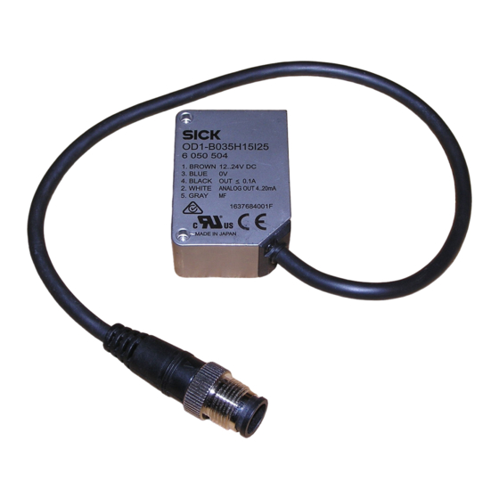
Distance sensor OD Mini Prime
with display and analog output
Operating Instructions
OD Mini Prime
CLASS 1 LASER
PRODUCT
MAX. OUTPUT ≤ 390 µ W
WAVELENGTH = 655 nm
EN/IEC 60825-1:2007
Complies with 21 CFR
1040.10 and 1040.11
except for deviations
pursuant to laser notice
No. 50, dated June 24, 2007
Safety notes
Australia
Phone +61 3 9457 0600
•
CAUTION: Use of controls or adjustments or performance
Belgium/Luxembourg
Phone +32 (0)2 466 55 66
of procedures other than those specified herein may re-
Brasil
Phone +55 11 3215-4900
sult in hazardous radiation exposure.
Canada
•
Read the Operating Instructions before starting opera-
Phone +1 905 771 14 44
Česká republika
tion.
Phone +420 2 57 91 18 50
•
Connection, mounting and setting must be performed by
China
Phone +86 4000 121 000
qualified personnel.
•
Danmark
Protect devices from moisture and contamination during
Phone +45 45 82 64 00
commissioning.
Deutschland
Phone +49 211 5301-301
•
Not free of paint-wetting impairment substances.
España
•
Phone +34 93 480 31 00
No safety component pursuant to EU directive.
France
Phone +33 1 64 62 35 00
Intended use
Great Britain
Phone +44 (0)1727 831121
The distance sensor OD Mini Prime is an optoelectronic sen-
India
Phone +91–22–4033 8333
sor and is used for optical determination of object distances
Israel
Phone +972-4-6801000
without contact.
Italia
Phone +39 02 27 43 41
Scope of delivery
Japan
Phone +81 (0)3 5309 2112
Sensor OD Mini Prime, 2x M3 screws, laser warning label
Magyarország
Phone +36 1 371 2680
and Operating Instructions
Nederland
Phone +31 (0)30 229 25 44
Commissioning
! Mount sensor.
— For steps, eccentricity measurements of round
Please find detailed addresses and additional representatives and agencies in
objects and strong contrast changes, consider the
all major industrial nations at www.sick.com
preferred direction of the sensor. See Fig. C.
" Align sensor.
— Align sensor so that object is within measuring range.
See Tab. G. Display indicates distance from center of
measuring range. If 9999 is displayed, measurement
Function
is not possible. Object may be out of measuring
n_P =
range.
PNP
§ Electrical connection: Connect cable socket tension free
and tighten the screw. See Fig. D.
$ Connect sensor to supply voltage. Operating display is
n_P =
lit. Consider warm-up time for best measuring results.
NPN
See Tab. G.
% Perform parameterization. See Fig. H and Tab. I.
Maintenance
Operation via operating keys
It is recommended to regularly clean the external lens
Perform teach-in (see Fig. F, Fig. H and Tab. I)
surfaces and to check the screw connections and plug con-
! Align distance sensor with the distance to be taught-in.
nections.
" Select teach option via parameter MoDE and teach-in
switching point:
— 1Pt (1-point teach): Switching point FAr. See Fig. F1.
— 2Pt (2-point teach): Switching point nEAr and FAr.
See Fig. F2.
— Obsb (background): Switching point ObSb.
See Fig. F3.
§ If necessary, enter hysteresis (hYst) and tolerance (tol).
See Fig. H and Tab. I.
Zeroing
The distance sensor is in RUN mode.
•
Set value to zero: Press key ZERO/RUN for 2 seconds.
The display shows 0.00 when successfully reset.
This corresponds to 12 mA/5 V at factory settings.
•
Recover value: Press key ZERO/RUN for 4 seconds.
Key lock (see Fig. H)
The distance sensor is in RUN mode.
•
On: Press – and + key for 3 seconds simultaneously.
Sicherheitshinweise
•
Off: Press – and + key for 3 seconds simultaneously.
•
Vor allen Arbeiten die Betriebsanleitung lesen.
Operation via multifunctional input
•
Anschluss, Montage und Einstellung nur durch Fachper-
sonal.
! Select function for the multifunctional input (MF).
•
Gerät bei Inbetriebnahme vor Feuchte und Verunreini-
See Fig. H and Tab. I.
gung schützen.
" Apply signal to input MF.
•
Nicht frei von lackbenetzungsstörenden Substanzen.
Table Timing
•
Kein Sicherheitsbauteil gemäß EU-Maschinenrichtlinie.
Selected
Description
Signal to
Bestimmungsgemäße Verwendung
function
MF
Der Distanzsensor OD Mini Prime ist ein optoelektronischer
tch
Teach-in current distance to the object as
0.7 ... 1.3 s
Sensor und wird zur optischen, berührungslosen Distanz-
(Teach)
4 mA/0 V-value. See Fig. E.
messung eingesetzt.
Teach-in current distance to the object as
1.7 ... 2.3 s
10 mA/10 V-value. See Fig. E.
Lieferumfang
Teach-in current distance to the object as
2.7 ... 3.3 s
OD Mini Prime Sensor, Befestigungswinkel, 2x M3 Schrau-
far switching point (FAr). See Fig. F1.
ben, Laserwarnschild und Betriebsanleitung
Teach-in current distance to the object as
3.7 ... 4.3 s
near switching point (nEAr). See Fig. F2.
Inbetriebnahme
Teach-in current distance to the object as
> 4.5 s
! Sensor montieren.
background (ObSb). See Fig. F3.
— Bei Stufen, Exzentrizitätsmessungen von runden Ob-
ZEro
Perform zeroing.
0 s ... 2000
jekten und bei starken Kontrastwechseln Vorzugsrich-
x SAMP
tung des Sensors beachten. Siehe Abb. C.
Reset zeroing.
> 2000 x
" Sensor ausrichten.
SAMP
— Das Objekt muss im Messbereich liegen. Siehe
Function MF depending on the setting of the parameter n_P
Tab. G. Das Display zeigt den Abstand von der Mess-
(see Fig. H and Tab. I). Example:
bereichsmitte an. Wird 9999 angezeigt, ist keine Mes-
sung möglich. Objekt liegt z. B. außerhalb des Mess-
bereiches.
§ Elektrischer Anschluss: Leitungsdose spannungsfrei auf-
stecken und festschrauben. Siehe Abb. D.
$ Sensor an Versorgungsspannung legen. Betriebsanzeige
leuchtet. Für optimale Messergebnisse Aufwärmzeit be-
achten. Siehe Tab. G.
% Parametrierung durchführen. Siehe Abb. H und Tab. I.
8015609/YF42/2015-04/HS_8M
Bedienung über Bedientasten
Teach-in durchführen (siehe Abb. F, Abb. H und Tab. I)
! Distanzsensor auf einzulernende Distanz ausrichten.
" Teach-Option über Parameter MoDE wählen und Schalt-
punkt einlernen:
— 1Pt (1-Punkt-Teach): Schaltpunkt FAr. Siehe Abb. F1.
NFPA79 applications only.
— 2Pt (2-Punkt-Teach): Schaltpunkt nEAr und FAr. Sie-
Adapters providing field
he Abb. F2.
wiring leads are available.
as marked on device
Refer to the product information.
— Obsb (Hintergrund): Schaltpunkt ObSb. Siehe Abb. F3.
§ Ggf. Hysterese (hYst) und Toleranz (tol) eingeben. Siehe
Abb. H und Tab. I.
Österreich
Phone +43 (0)22 36 62 28 8-0
Norge
Nullpunktverschiebung
Phone +47 67 81 50 00
Polska
Der Distanzsensor befindet sich im RUN-Mode.
Phone +48 22 837 40 50
•
Wert auf Null setzen: Taste ZERO/RUN für 2 Sekunden
România
Phone +40 356 171 120
drücken. Bei erfolgreicher Rücksetzung zeigt das Display
Russia
Phone +7-495-775-05-30
0.00 an, dies entspricht 12 mA/5 V bei Werkseinstellung.
Schweiz
•
Wert wieder herstellen: Taste ZERO/RUN für 4 Sekunden
Phone +41 41 619 29 39
+852-2153 6300
Singapore
drücken.
Phone +65 6744 3732
Slovenija
Tastensperre (siehe Abb. H)
Phone +386 (0)1-47 69 990
South Africa
Phone +27 11 472 3733
Der Distanzsensor befindet sich im RUN-Mode.
South Korea
•
Ein: Taste – und + gleichzeitig für 3 Sekunden drücken.
Phone +82 2 786 6321/4
Suomi
•
Aus: Taste – und + gleichzeitig für 3 Sekunden drücken.
Phone +358-9-25 15 800
Sverige
Bedienung über Multifunktionseingang
Phone +46 10 110 10 00
Taiwan
Phone +886-2-2375-6288
! Funktion Multifunktionseingang (MF) wählen.
Türkiye
Siehe Abb. H und Tab. I.
Phone +90 (216) 528 50 00
United Arab Emirates
" Signal an Eingang MF legen.
Phone +971 (0) 4 8865 878
USA/México
Tabelle Zeiteinstellung
Phone +1(952) 941-6780
Gewählte
Beschreibung
Funktion
tch
Aktuelle Distanz zum Objekt als 4 mA/0 V-
(Teach)
Wert einlernen. Siehe Abb. E.
Aktuelle Distanz zum Objekt als
20 mA/10 V-Wert einlernen. Siehe Abb. E.
Aktuelle Distanz zum Objekt als nahen
Schaltpunkt einlernen (FAr). Siehe Abb. F1.
Subject to change without notice
Aktuelle Distanz zum Objekt als fernen
Irrtümer und Änderungen vorbehalten
Schaltpunkt einlernen (nEAr).
Siehe Abb. F2.
Description
Aktuelle Distanz zum Objekt als Hintergrund
• Apply MF to 12 ... 24 V DC:
einlernen (ObSb). Siehe Abb. F3.
MF active e.g. Laser on
ZEro
Nullpunktverschiebung ausführen.
• Apply MF to 0 V or open:
MF inactive, e.g. laser off
• Apply MF to 0 V or open:
Nullpunktverschiebung zurücksetzen.
MF active e.g. Laser on
• Apply MF to 12 ... 24 V DC:
MF inactive, e.g. laser off
Funktion MF abhängig von der Einstellung des Parameters
n_P (siehe Abb. H und Tab. I). Beispiel:
Funktion
Beschreibung
n_P =
• MF an 12 ... 24 V DC anlegen:
PNP
MF aktiv z.B. Laser on
• MF an 0 V anlegen oder öffnen:
MF inaktiv z.B. Laser off
n_P =
• MF an 0 V anlegen oder öffnen:
Deutsch
NPN
MF aktiv z.B. Laser on
Distanzsensor OD Mini Prime
• MF an 12 ... 24 V DC anlegen:
mit Display und Analogausgang
MF inaktiv z.B. Laser off
Betriebsanleitung
Wartung
Es wird empfohlen in regelmäßigen Abständen die optischen
Grenzflächen zu reinigen und Verschraubungen, sowie Steck-
verbindungen zu überprüfen.
CLASS 1 LASER
PRODUCT
G
MAX. OUTPUT ≤ 390 µ W
Technical Data / Technische Daten
WAVELENGTH = 655 nm
EN/IEC 60825-1:2007
Complies with 21 CFR
1040.10 and 1040.11
except for deviations
pursuant to laser notice
No. 50, dated June 24, 2007
Measuring range /Messbereich
15 ± 5 mm
35 ± 15 mm
100 ± 50 mm
Housing material /
Gehäusematerial
Stainless steel / Edelstahl
Aluminum / Aluminium
Output / Ausgang
4 ... 20 mA (≤ 300 Ω)
0 ... 10 V (≥ 10 kΩ)
Multifunctional input/Switching
output /Multifunktionseingang/
Schaltausgang
1 x MF
5)
1 x PNP/NPN
6)
, 1 x MF
Connection / Anschluss
M8 plug, 4-pin / M8-Stecker, 4-polig
Cable with M12 plug, 5-pin /
Leitung mit M12-Stecker, 5-polig
1)
At set averaging 512
2)
Constant ambient conditions
Measurement on 90 % remission (ceramic, white)
3)
4)
For best performance consider warm up time ≤ 5 min.
5)
MF can be used as laser-off, trigger, external teach-in or deactivated
PNP/NPN selectable, 30 V (100 mA max), 1.8 V (100 mA max)
6)
A
Dimensions / Abmessungen
OD1-xxxxHxxxxx
Edelstahl/Stainless steel
31
(1.22)
3
2 x M3
(0.12)
1
16
(0.63)
All dimensions in mm (inch)
Type with 30 cm cable with M12, 5 pin connector /
1
Variante mit Anschlussleitung 30 cm mit Stecker M12, 5-pin
2
Optical axis / Optische Achse
3
Distance optical axis sender to receiver /
Abstand optische Achse Sender zu Empfänger:
OD1-B015x: 8.1 mm / OD1-B35x: 12.6 mm /
OD1-B100x: 15.5 mm
4
Optical axis receiver / Optische Achse Empfänger
5
Optical axis sender / Optische Achse Sender
C
Preferred mounting direction /
Vorzugsrichtung der Sensormontage
Signal an
MF
0,7 ...
1,3 s
1,7 ...
2,3 s
2,7 ...
3,3 s
3,7 ...
4,3 s
> 4,5 s
0 s ...
2000 x
SAMP
> 2000 x
SAMP
E
Analog output / Analogausgang
Analog
Output
approx. 24 mA
(approx. 15 V)
20 mA
(10 V)
4 mA
(0 V)
4mA
(
)
0V
Resolution
1)
Repeatability
Linearity
1), 2)
1)
Auflösung
Reproduzier-
Linearität
OD1-
barkeit
1), 2)
B015
05
1 μm
3 μm
± 10 μm
B035
15
6 μm
9 μm
± 30 μm
B100
50
20 μm
30 μm
± 100 μm
H
C
I
U
1
5)
2
4
5
1)
Bei Mittelwerteinstellung 512
2)
Konstante Rahmenbedingungen
Messung auf 90 % Remission (Keramik, weiß)
3)
4)
Für optimale Messergebnisse max. Aufwärmzeit von 5 Min. beachten.
5)
Funktion für MF wählbar: Laser aus, Trigger, externer Teach-in oder deaktiviert
PNP/NPN wählbar, 30 V (100 mA max), 1,8 V (100 mA max)
6)
OD1-xxxxCxxxxx
Aluminium/Aluminum
17
31
17,8
(1.22)
(0.67)
(0.7)
3
1.1
2 x M3
2
(0.12)
(0.04)
4
3
1
5
16
(0.63)
D
Electrical connection / Elektrischer Anschluss
OD1-Bxxxxxxx1x
M8, 4-pin
2
4
1
brn
L+ (12 V ... 24 V)
wht
2
Q
A
3
blu
0 V
1
3
4
blk
MF
1
F
Switching output behavior / Schaltausgangsverhalten
F1
F2
ModE: 1Pt
1
FAr
OD
Min
Max
hYSt
RUN Mode
RUN Mode
SET
MEnu
MEnu
–
+
–
+
SET
ModE
ModE
2Pt
1pt
obSb
SET
Teach-in current
–
+
distance
SET
FAr
tch
nEAr
ZERO
RUN
RUN Mode
RUN Mode
Distance
20mA
(
)
10V
3), 4
Typ. light spot
OD1-
dimension
Light source
Laser, red
(Distance)
Laser protection class
1)
1 (EN 60825-1)
3), 4
Response time
2)
2 ms / 4 ms / 8 ms / 16 ms / Auto
Typ. Lichtfleckab-
messung (Distanz)
Measuring frequency
2 kHz / 1 kHz / 500 Hz / 250 Hz / Auto
Supply voltage V
4)
12 V DC (–5 %) ... 24 V DC (+10 %)
S
Power consumption
≤ 1,92 W (without load, incl. current output)
700 μm x 500 μm
Warm up time
≤ 5 min
(15 mm)
Material
Housing: stainless steel or aluminum,
800 μm x 450 μm
Front window: PPSU
(35 mm)
Weight
with stainless steel housing: 70 g,
700 μm x 600 μm
with aluminum housing: 40 g
(100 mm)
Enclosure rating
IP 67
Protection class
III
Ambient temperature
Operation: –10 ... +40 °C at rel. humidity
35 % ... 95 % (not condensing)
Storage: –20 ... +60 °C
Typ. ambient light safety
Artificial light: ≤ 3.000 lx;
Sunlight: ≤ 10.000 lx
Temperature drift
± 0.08 % FS/K (FS: Full Scale: Measuring
range of sensor)
Vibration resistance
10 ... 55 Hz (Amplitude 1,5 mm; x-, y- and
z-axis 2 hours each)
Shock resistance
50 G (x-, y- and z-axis 3 times each)
1)
Wavelength 655 nm, max. output: 390 μW
2)
At fixed sensitivity setting and averaging =1
Sampling rate 500µs: 2 ... 7.5 ms response time/ sampling rate 1000µs:
3)
4 ... 15 ms response time
4)
When using analog voltage output reduced to DC 18 V (–5 %) ... DC 24 V
(+ 10 %)
B
Display and operating elements /
Display und Bedienelemente
1
2
ZERO
OUT
+
ZERO
RUN
5
–
1.1
SET
2
(0.04)
LASER
MANUAL
4
3
Status switching output /
1
Status Schaltausgang
4
2
Status zeroing /
Status Nullpunktverschiebung
3
Status Teach mode /
5
3
Status Teach-Modus
4
Status laser
Status Laser
5
Minus sign for measured value indicator /
Minuszeichen für Messwertanzeige
OD1-Bxxxxxxx2x
M12, 5-pin
brn
brown
braun
wht
white
weiß
4
5
3
1
blu
blue
blau
brn
L+ (12 V ... 24 V)
blk
black
schwarz
wht
2
Q
A
gra
grey
grau
3
blu
0 V
1
2
4
blk
Output
1 Multifunctional input
Multifunktionseingang
5
gra
MF
1
F3
ModE: 2Pt
ModE: obSb
1
1
2
nEAr
FAr
obSb
hYSt
hYSt
OD
OD
Min
Max
Min
hYSt
hYSt
tol
tol
RUN Mode
SET
SET
MEnu
–
+
–
+
–
+
–
+
SET
SET
ModE
2Pt
1pt
obSb
2Pt
1pt
obSb
SET
SET
Teach-in current
Teach-in current
–
+
–
+
distance
distance
SET
SET
tch
obSb
tch
Teach-in current
ZERO
–
+
RUN
distance
SET
RUN Mode
FAr
tch
ZERO
RUN
Switching
point
Hysteresis
1. Teach-in point
1
2
2. Teach-in point
OD1-
Lichtsender
Laser, rot
Laserschutzklasse
1)
1 (EN 60825-1)
3)
Ansprechzeit
2)
2 ms / 4 ms / 8 ms / 16 ms / Auto
3)
Messfrequenz
2 kHz / 1 kHz / 500 Hz / 250 Hz / Auto
Versorgungsspannung U
4)
12 V DC (–5 %) ... 24 V DC (+10 %)
V
Leistungsaufnahme
≤ 1,92 W (ohne Last, inkl. Stromausgang)
Aufwärmzeit
≤ 5 min
Material
Gehäuse: Edelstahl oder Aluminium,
Frontscheibe: PPSU
Gewicht
mit Edelstahlgehäuse: 70 g,
mit Aluminiumgehäuse: 40 g
Schutzart
IP 67
Schutzklasse
III
Umgebungsbedingungen
Betrieb: –10 ... +40 °C bei rel. Feuchte
35 % ... 95 % (nicht kondensierend)
Lagerung: –20 ... +60 °C
Fremdlichtsicherheit
Künstliches Licht: ≤ 3.000 lx;
Sonnenlicht: ≤ 10.000 lx
Temperaturdrift
± 0,08 % FS/K (FS: Full Scale: Messbereich
des Sensors)
Vibrationsfestigkeit
10 ... 55 Hz (Amplitude 1,5 mm; x-, y- und
z-Achse jeweils 2 Stunden)
Stoßfestigkeit
50 G (x-, y- und z-Achse jeweils 3 Mal)
1)
Wellenlänge 655 nm, max. Leistung: 390 μW
2)
Bei fixer Empfindlichkeitseinstellung und Mittelwertbildung =1
Messrate 500µs: 2 ... 7,5 ms Ansprechzeit/Messrate 1000µs: 4 ... 15 ms
3)
Ansprechzeit
4)
Bei Nutzung des analogen Spannungsausganges reduzierte Grenzen auf
DC 18 V (–5 %) ... DC 24 V (+ 10 %)
Max

Verwandte Anleitungen für SICK OD Mini Prime


Inhaltszusammenfassung für SICK OD Mini Prime
- Seite 1 Phone +358-9-25 15 800 Optical axis receiver / Optische Achse Empfänger Phone +44 (0)1727 831121 Sverige The distance sensor OD Mini Prime is an optoelectronic sen- Bedienung über Multifunktionseingang India Phone +46 10 110 10 00 Optical axis sender / Optische Achse Sender Phone +91–22–4033 8333...
- Seite 2 ZERO tivated. • Bei Einstellung ALrM (Alarm) = cLMP tout These parameters are not relevant for (Clamp), ist der Parameter hdct deak- OD Mini Prime with analog output. It is tiviert. tHrE bASE not recommended to make settings. tout Diese Parameter sind für OD Mini Prime NtoP mit Analogausgang nicht relevant.