
Verwandte Anleitungen für Viscount Pipe 27


Inhaltszusammenfassung für Viscount Pipe 27
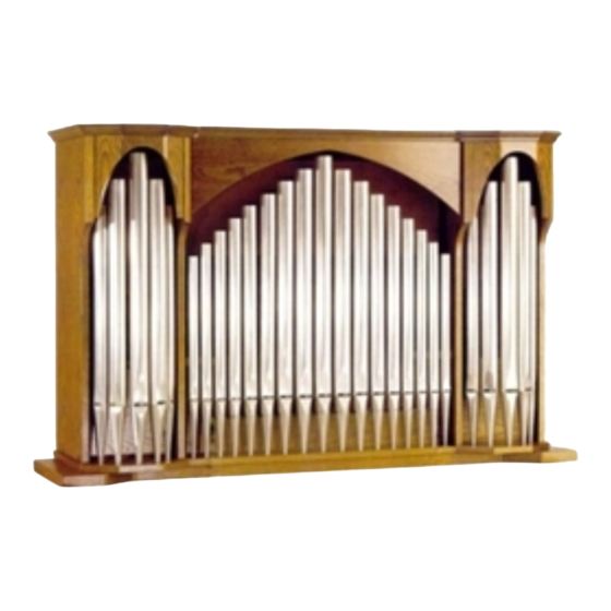
- Seite 1 Pipe 27 Manuale Operativo Owner's Manual Mode d ' Emploi Bedienungsanleitung...
-
Seite 2: Avis Important
∗∗∗ WARNING: READ THIS FIRST! AVIS IMPORTANT! WARNING RISK OF ELECTRIC SHOCK DO NOT OPEN AVIS RISQUE DE CHOC ÉLECTRIQUE NE PAS OUVRIR This symbol is intended to alert the user to the Ce simbole sert pour avertir l’utilisateur presence of uninsulated “dangerous voltage” qu’à... -
Seite 3: Pannello Di Controllo
1. Prese INPUT L/M – R: prese Jack a cui collegare i cavi provenienti dalle uscite ANTIPHONAL OUT presenti sul pannello posteriore del Vostro organo VISCOUNT. In caso di utilizzo dell’uscita ANTIPHONAL OUT 1(+2) collegate l’ingresso L/M. In caso di utilizzo della coppia di uscite 1(+2) e 3(+4) utilizzate entrambi i connettori L/M e R. -
Seite 4: Procedura Di Assemblaggio
Pipe 27 2. PROCEDURA DI ASSEMBLAGGIO 1. Posizionare la base [A] sopra l’organo verificando che i fianchi dei due mobili coincidano. 2. Avvitare nei fianchi [B] i piedini [H]. - Seite 5 Pipe 27 3. Fissare i fianchi [B] alla base [A] inserendo i ciondoli [C] nei fori [D]. 4. Svitare dall’organo le viti [E] (1a e 4a dall’alto) e riavvitarle con gli angolari [F]. Regolare i piedini [H] al fine di ottenere una...
- Seite 6 [B] dove verranno avvitate quattro viti 4 x 16 TCFR ([G] nel disegno) al fine di fissare i fianchi [B] con gli angolari [F]. 6. Posizionare il Pipe 27 sopra la base [A] verificando che lo stesso sia ben centrato con la base sottostante. Quindi praticare otto prefori [J] (∅...
-
Seite 7: Control Panel
1. CONTROL PANEL 1. INPUT L/M - R Jack sockets: for the connection to the ANTIPHONAL OUT output sockets located on the rear panel of the VISCOUNT organ. To use the ANTIPHONAL OUT 1(+2), please connect to the L/M input. -
Seite 8: Assembling Instructions
Pipe 27 2. ASSEMBLING INSTRUCTIONS 1. Set the base [A] on the organ. 2. Fix the rubber feet [H] to the side panels [B]. - Seite 9 Pipe 27 3. Fix the side panels [B] to the base [A] inserting the pins [C] in the holes [D]. 4. Unscrew from the organ the screws [E] and 4 from the top) and screw them to the iron corners [F]. Adjust the rubber feet...
- Seite 10 4 screw, 4x 16 TCFR [G] fixing the side panels [B] with the iron corners [F]. 6. Set the Pipe 27 on to the base [A] and check it is central. Drill 8 holes [J] (∅ 3 mm.) where to...
-
Seite 11: Panneau De Contrôle
1. Connecteurs INPUT L/M - R: pour effecteur (à l’aide de cablês appropriés) la connection aux sorties ANTIPHONAL OUT situées sur le panneau arriére de votre orgue VISCOUNT. Si vous utilisez une seule sortie ANTIPHONAL OUT 1(+2), connectez vous sur l’entreé repérée L/M. -
Seite 12: Instructions D'assemblage
Pipe 27 2. INSTRUCTIONS D’ASSEMBLAGE 1. Installez la base [A] sur l’orgue. 2. Fixez les panneaux latéraux [B] à travers le joint de caoutchouc [H]. - Seite 13 Pipe 27 3. Fixez les panneaux latéraux [B] sur la base [A] en insérant les chevilles [C] dans les trous [D]. 4. Dévissez sur l’orgue les vis [E] (1 éme à partir du haut) et re-vissez les après avoir ajusté les cornières en acier [F]. Ajustez...
- Seite 14 TCFR [G] fixez les panneaux latéraux [B] avec les cornières en acier [F]. 6. Installez le Pipe 27 sur la base [A] et vérifiez qu’il est bien positionné au centre. Percez 8 trous [J] (∅ 3 mm.) afin de visser les 4 vis de type 4 x...
- Seite 15 Orgel benutzen, verbinden Sie diese mit den Buchsen L/M und R. 2. 12V DC Buchse: fuer den Anschluss ueber ein 2-adriges Kabel an die EXT +12V DC Buchse, die sich auf die Rueckseite Ihrer VISCOUNT Orgel befindet. Damit kann das Pipe-Cabinet von der Orgel her aus-und eingeschaltet werden.
-
Seite 16: Hinweise Zum Aufbau
Pipe 27 2. HINWEISE ZUM AUFBAU 1. Setzen Sie den Sockel [A] auf die Orgel. 2. Befestigen Sie die Gummifuesse [H] und die Seiten [B]. - Seite 17 Pipe 27 3. Befestigen Sie die Stifte [A] an den Seiten [B] und stecken die Stifte [C] in den Bohrungen [D]. 4. Drehen Sie die Schrauben [E] (1. und 4. von oben) von der Orgel auf und schrauben Sie sie zusammen mit dem Metallescken [F] wieder an.
- Seite 18 (Bfuer die 4 4 x 16 TCFR Schrauben [G] und befestigen Sie die Seitenteilen [B] mit den Metallecken [F]. 6. Setzen Sie das Oberteil des Pipe 27 auf den Sockel [A] und kontrollieren Sie die Mittenposition. Bohren Sie 8 Loecher [J] (3 mm) in die 4 x 40 TS...
- Seite 19 NOTE: This equipment has been tested and found to comply with the limits for a Class B digital Device, persuant to Part 15 if the FCC Rules. These limits are designed to provide reasonable protection against harmful interference in a residential installation. This equipment generates, uses and can radiate radio frequency energy and, if not installed and used in accordance with the instruction, may cause harmful interference to radio comunications.
- Seite 20 Intercontinental Electronics S.p.A. P.O. BOX 5 Mondaino (RN) - Italy From Italy: TEL: 0541-981700 FAX: 0541-981052 From all other countries: TEL: +39-0541-981700 FAX: +39-0541-981052 E-MAIL: viscount@omniway.sm WEB: http://www.viscount-organs.com http://www.viscount.it...