Herunterladen Inhalt Inhalt Diese Seite drucken
Inhaltsverzeichnis

Werbung

Verfügbare Sprachen
  • DE

Verfügbare Sprachen

  • DEUTSCH, seite 1
ISM 1
ISM 2
de
Installationsanleitung
fr
Notice d'installation
it
Istruzioni per l'uso
nl
Installatiehandleiding
es
Instrucciones de instalación
2
pt
Instruções de instalação
10
cz
Návod k instalaci
18
sk
Návod na montáž
26
34
42
50
58

Werbung

Inhaltsverzeichnis
loading

Inhaltszusammenfassung für Junkers ISM 1

  • Seite 1 ISM 1 ISM 2 Installationsanleitung Instrucciones de instalación Notice d’installation Instruções de instalação Istruzioni per l’uso Návod k instalaci Installatiehandleiding Návod na montáž...
  • Seite 2: Inhaltsverzeichnis

    • Ergänzendes Zubehör Serviceheft (für Fehlersuche und Funktions- • prüfung) Installation Diese Unterlagen können beim Junkers Info- Montage Dienst angefordert werden. Die Kontaktadresse 3.1.1 Montage an der Wand finden Sie auf der Rückseite dieser Anleitung. 3.1.2 Montage auf der Montageschiene 3.1.3 Demontage von der Montageschiene...
  • Seite 3: Sicherheitshinweise Und Symbolerklärung

    Sicherheitshinweise und Symbolerklärung Sicherheitshinweise und Symbolerklärung Sicherheitshinweise Symbolerklärung B Für einwandfreie Funktion diese Anleitung Sicherheitshinweise im Text wer- beachten. den mit einem Warndreieck ge- B Heizgerät und weitere Zubehöre entspre- kennzeichnet und grau hinterlegt. chend den zugehörigen Anleitungen montie- ren und in Betrieb nehmen. Signalwörter kennzeichnen die Schwere der B Zubehör nur von einem zugelassenen Installa- Gefahr die auftritt, wenn die Maßnahmen zur...
  • Seite 4: Angaben Zum Zubehör

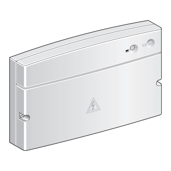
    Bestimmungsgemäßer Lieferumfang Gebrauch Bild 1 auf Seite 66 und 10 auf Seite 69: Die Module ISM 1 und ISM 2 dienen zur Ansteue- ISM 1 bzw. ISM 2 rung der Komponenten einer Solaranlage inner- Schrauben zur Befestigung des Oberteils halb einer Heizungsanlage mit den Reglern Brücke;...
  • Seite 5: Technische Daten

    Angaben zum Zubehör Technische Daten Messwerte Vorlauftemperaturfühler und Spei- Lieferumfang chertemperaturfühler - ISM 1 Bild 1, Seite 66 Ω Ω - ISM 2 Bild 10, Seite 69 °C °C 14772 3723 Abmessungen 11500 3032 - ISM 1 Bild 2, Seite 66...
  • Seite 6: Installation

    ≤ 150 m 0,75 mm 3.1.1 Montage an der Wand ≤ 200 m 1,00 mm ISM 1 Bild 2 bis 5 ab Seite 66 ≤ 300 m 1,50 mm ISM 2 Bild 11 bis 14 ab Seite 69 B Um induktive Beeinflussungen zu vermeiden: Alle Niederspannungsleitungen von 230 V 3.1.2...
  • Seite 7: Anschluss 230 V Ac

    Speichern zur Trinkwassererwärmung und thermischer Desinfektion aller Speicher (System 1-ABCDE): Bild 19 auf Seite 72 ISM 2 und ISM 1 in Solaranlage mit zwei Kollek- torfeldern, mit Solarspeicher zur Trinkwasser- erwärmung mit thermischer Desinfektion und über Wärmetauscher angeschlossenem Solar- pufferspeicher zur Heizungsunterstützung...
  • Seite 8: Montage Des Ergänzenden Zubehörs

    (Speicher C) Solarkollektor Speichertemperaturfühler Heizkreis (Heizgerät) HKRL Heizkreisrücklauf Solarkreispumpe für HKVL Heizkreisvorlauf 1. Kollektorfeld ISM 1 Modul für Standardsolaranlagen Kollektortemperaturfühler 1. Feld Heizwasserseitiger Speichertem- ISM 2 Modul für erweiterte Solaranlagen peraturfühler unten (Solarspei- Heizungspumpe cher) Kaltwasseranschluss Heizwasserseitiger Speichertem- Anschluss für Temperaturfühler 1...6...
  • Seite 9: Inbetriebnahme

    Inbetriebnahme Inbetriebnahme Vorsicht: Fehlfunktion durch zeit- lich versetzte Inbetriebnahme. B Alle Busteilnehmer am Bus an- schließen bevor der Bus mit Spannung versorgt wird. Störungen Die Betriebsanzeige zeigt den Betriebszustand des Zubehörs. Störungen werden in der Anzeige des Reglers oder der betroffenen Fernbedienung angezeigt. Betriebsanzeige Reaktion des ISM Störung/Abhilfe...
  • Seite 10 • Accessoires complémentaires pannes et le contrôle de fonctionnement) Ces documents sont disponibles auprès du ser- Installation vice d’information Junkers. Vous trouverez Montage l’adresse correspondante au verso de cette 3.1.1 Montage au mur notice. 3.1.2 Montage sur le rail de montage 3.1.3 Démontage depuis le rail de montage...
  • Seite 11: Mesures De Sécurité Et Explication Des Symboles

    Mesures de sécurité et explication des symboles Mesures de sécurité et explication des symboles Mesures de sécurité Explication des symboles B Respecter ces instructions afin d’assurer un Les indications relatives à la fonctionnement impeccable. sécurité sont écrites sur un fond B Monter et mettre en service la chaudière et les grisé...
  • Seite 12: Indications Concernant Les Accessoires

    Indications concernant les accessoires Indications concernant les accessoires Utilisation conforme Pièces fournies Les modules ISM 1 et ISM 2 servent à la com- Illustration 1 page 66 et 10 page 69: mande des composants d’une installation solaire ISM 1 ou ISM 2...
  • Seite 13: Caractéristiques Techniques

    Indications concernant les accessoires Caractéristiques techniques Valeurs mesurées par la sonde de température Pièces fournies de départ et la sonde de température de ballon - ISM 1 Illustration 1, page 66 Ω Ω °C °C - ISM 2 Illustration 10,...
  • Seite 14: Installation

    3.1.1 Montage au mur ≤ 300 m 1,50 mm ISM 1 Illustrations 2 à 5 à partir de la page 66 B Pour éviter des effets inductifs : poser séparé- ISM 2 Illustrations 11 à 14 à partir de la...
  • Seite 15: Branchement 230 V Ac

    (système 1-ABCDE) : Illustration 19 page 72 ISM 2 et ISM 1 dans une installation solaire à deux champs collecteurs, avec ballon solaire pour le réchauffage d’eau potable, désinfection thermique et réservoir tampon solaire, raccordé...
  • Seite 16: Montage Des Accessoires Complémentaires

    HKRL Retour du circuit de chauffage champ collecteur HKVL Départ du circuit de chauffage Sonde de température de collecteur ISM 1 Module pour les installations pour le 1er champ collecteur solaires standard Sonde de température située dans le ISM 2 Module pour les installations solaires bas du ballon, côté...
  • Seite 17: Mise En Service

    Mise en service Mise en service Prudence : Dysfonctionnement dû à une mise en service décalée dans le temps. B Raccorder tous les composants BUS avant d’allumer l’alimenta- tion en tension du BUS. Anomalies Le témoin de fonctionnement indique l’état de service de l’accessoire.
  • Seite 18: Informazioni Sulla Documentazione

    Dati tecnici guasti e il controllo del funzionamento). Accessori integrativi Questi documenti possono essere richiesti al ser- vizio informazioni di Junkers. L’indirizzo per i Installazione contatti è riportato sul retro di questo manuale. Fissaggio a parete 3.1.1 Montaggio a parete 3.1.2 Montaggio su barra...
  • Seite 19: Avvertenze E Spiegazione Dei Simboli

    Avvertenze e spiegazione dei simboli Avvertenze e spiegazione dei simboli Avvertenze Spiegazione dei simboli pre- senti nel libretto B Soltanto attenendosi alle istruzioni presenti può essere garantito un perfetto funziona- Gli avvisi per la sicurezza vengono mento. contrassegnati nel testo con un B Montare e mettere in funzione la caldaia e gli triangolo di avvertimento su sfondo altri accessori in conformità...
  • Seite 20: Caratteristiche Principali Degli Accessori

    Caratteristiche principali degli accessori Uso conforme alle indicazioni Fornitura I moduli ISM 1 e ISM 2 servono per il comando dei Figura 1 a pagina 66 e 10 a pagina 69: componenti di un impianto a energia solare ISM 1 o ISM 2 nell’ambito di un impianto di riscaldamento con...
  • Seite 21: Dati Tecnici

    Caratteristiche principali degli accessori Dati tecnici Valori di misurazione sensore temperatura di Materiale in dotazione mandata e sensore temperatura bollitore - ISM 1 Figura 1, pagina 66 Ω Ω °C °C - ISM 2 Figura 10, 14772 3723 pagina 69...
  • Seite 22: Installazione

    1,00 mm 3.1.1 Montaggio a parete ≤ 300 m 1,50 mm ISM 1 Figure da 2 a 5 da pagina 66 B Per evitare disturbi elettromagnetici, posare ISM 2 Figure da 11 a 14 da pagina 69 tutte le linee a bassa tensione separatamente 3.1.2...
  • Seite 23: Collegamento A 230 V Ac

    (sistema a-ABCDE): Figura 19 a pagina 72 ISM 2 e ISM 1 nell’impianto a energia solare con due campi collettore, con bollitore solare per il riscaldamento dell’acqua potabile con disinfe-...
  • Seite 24: Installazione Degli Accessori Integrativi

    HKRL Ritorno del circuito di riscaldamento (caldaia) HKVL Mandata del circuito di riscaldamento Pompa del circuito solare per ISM 1 Modulo per impianti a energia solare campo collettore 1 standard Sensore di temperatura collettore ISM 2 Modulo per impianti a energia solare...
  • Seite 25: Messa In Funzione Dell'apparecchio

    Messa in funzione dell’apparecchio Messa in funzione dell’apparecchio Prudenza: Malfunzionamento con tempi di messa in funzione sfalsa- B Collegare tutte le utenze bus prima di alimentare il bus con tensione. Blocco di funzionamento L’indicatore d’esercizio indica lo stato operativo dell’apparecchio. I guasti vengono visualizzati sul display della cen- tralina o sul telecomando rispettivo.
  • Seite 26 Aanvullend toebehoren Serviceboekje (voor het opsporen van fouten • en de functiecontrole) Installatie Deze documentatie kunt u bij de Junkers informa- Montage tiedienst aanvragen. Het contactadres vindt u op 3.1.1 Montage op de muur de achterkant van deze handleiding. 3.1.2 Montage op de montagerail 3.1.3 Demontage van de montagerail...
  • Seite 27: Veiligheidsvoorschriften En Verklaring Van De Symbolen

    Veiligheidsvoorschriften en verklaring van de symbolen Veiligheidsvoorschriften en verklaring van de symbo- Voor uw veiligheid Verklaring symbolen B Neem de gebruiksaanwijzing in acht voor een Veiligheidsaanwijzingen in de juiste werking. tekst worden door middel van een B Monteer het verwarmingstoestel en het ove- grijs vlak en een gevaren driehoek rige toebehoren en stel het in werking over- aangeduid.
  • Seite 28: Gegevens Over Het Toebehoren

    Gegevens over het toebehoren Gebruik volgens de voorschrif- Leveringsomvang Afbeelding 1 op pagina 66 en 10 op De modules ISM 1 en ISM 2 dienen voor de aan- pagina 69: sturing van de componenten van een solarinstal- ISM 1 of ISM 2...
  • Seite 29: Technische Gegevens

    Gegevens over het toebehoren Technische gegevens Meetwaarden aanvoertemperatuurvoeler en Meegeleverd boilertemperatuurvoeler - ISM 1 Afbeelding 1, pagina 66 Ω Ω °C °C - ISM 2 Afbeelding 10, 14772 3723 pagina 69 11500 3032 Afmetingen 9043 2488 - ISM 1 Afbeelding 2,...
  • Seite 30: Installatie

    ≤ 150 m 0,75 mm 3.1.1 Montage op de muur ≤ 200 m 1,00 mm ISM 1 Afbeelding 2 t/m 5 vanaf pagina 66 ≤ 300 m 1,50 mm ISM 2 Afbeelding 11 t/m 14 vanaf pagina 69 B Om inductieve beïnvloeding te voorkomen: Installeer alle laagspanningsleidingen geschei- 3.1.2...
  • Seite 31: Aansluiting 230 V Ac

    (systeem 1-ABCDE): Afbeelding 19 op pagina 72 ISM 2 en ISM 1 in solarinstallatie met twee col- lectorvelden, met zonneboiler voor drinkwater- verwarming met thermische desinfectie en via warmtewisselaar aangesloten bufferzonneboi-...
  • Seite 32: Montage Van Het Aanvullende Toebehoren

    (zonneboiler) Zonnecollector Boilertemperatuurvoeler Verwarmingscircuit heetwaterzijde midden (zonneboiler) HKRL Retour verwarmingscircuit Temperatuurvoeler HKVL Aanvoer verwarmingscircuit verwarmingsnetretour ISM 1 Module voor standaardsolarinstallaties Collectortemperatuurvoeler voor ISM 2 Modul voor uitgebreide 2e collectorveld solarinstallaties Boilertemperatuurvoeler voor Verwarmingspomp 2e boiler in opwarmsysteem Koudwateraansluiting...
  • Seite 33: Inbedrijfname

    Inbedrijfname Inbedrijfname Voorzichtig: Gestoorde functie door uitgestelde inbedrijfstelling. B Sluit alle busdeelnemers op de bus aan voordat u de bus van spanning voorziet. Storingen De functie-indicatie geeft de functietoestand van het toebehoren aan. Storingen worden in het display van de regelaar of van de desbetreffende afstandsbediening weergegeven.
  • Seite 34 Instalación Instalación Esta documentación puede solicitarla en el servi- 3.1.1 Montaje a la pared cio de información Junkers. La dirección se 3.1.2 Montaje sobre riel de sujeción indica al dorso de estas instrucciones. 3.1.3 Desmontaje del aparato del riel de sujeción...
  • Seite 35: Instrucciones De Seguridad Y Explicación De La Simbología

    Instrucciones de seguridad y explicación de la simbología Instrucciones de seguridad y explicación de la simbología Instrucciones de seguridad Explicación de la simbología B Para conseguir un funcionamiento correcto, Las instrucciones de seguridad aténgase a estas instrucciones. que figuran en el texto aparecen B Montar y poner en servicio la caldera y los sobre fondo gris y vienen identifi- accesorios de acuerdo a las respectivas ins-...
  • Seite 36: Indicaciones Sobre El Accesorio

    Indicaciones sobre el accesorio Utilización reglamentaria Material que se adjunta Los módulos ISM 1 y ISM 2 sirven para controlar Figuras 1 en página 66 y 10 en página 69: los componentes de una instalación solar que for- ISM 1 o ISM 2 man parte de una instalación de calefacción con...
  • Seite 37: Datos Técnicos

    Indicaciones sobre el accesorio Datos técnicos Valores óhmicos del sensor de temperatura de Volumen de suministro entrada y del acumulador - ISM 1 Figura 1, página 66 Ω Ω °C °C - ISM 2 Figura 10, 14772 3723 página 69...
  • Seite 38: Instalación

    1,00 mm 3.1.1 Montaje a la pared ≤ 300 m 1,50 mm ISM 1 Figuras 2 a 5 a partir de página 66 B Para evitar perturbaciones de origen induc- ISM 2 Figuras 11 a 14 a partir de página 69 tivo, tender todos los cables de baja tensión,...
  • Seite 39: Conexión A 230 V Ac

    (sistema 1-ABCDE): Figura 19 en página 72 ISM 2 y ISM 1 en instalación solar de dos pane- les y acumulador solar para calentamiento del agua sanitaria con desinfección térmica, y un acumulador solar tampón conectado a través de un intercambiador para apoyo de calefacción...
  • Seite 40: Montaje De Los Accesorios Complementarios

    Circuito de retorno de calefacción panel solar 1 HKVL Circuito de ida a la calefacción Sensor de temperatura de panel 1 Sensor inferior de temperatura en ISM 1 Módulo para instalaciones acumulador para agua de calefacción solares estándar (acumulador solar) ISM 2 Módulo para instalaciones...
  • Seite 41: Puesta En Marcha

    Puesta en marcha Puesta en marcha Precaución: Fallo funcional por puesta en marcha desfasada. B Conecte primero todos los componentes del bus antes de alimentarlo. Averías El indicador de servicio muestra el estado de ser- vicio de los accesorios. Las averías se indican en la pantalla del regulador o del mando a distancia afectado.
  • Seite 42 Instalação Esta documentação pode ser solicitada junto do Montagem serviço de informação da Junkers. Pode encon- 3.1.1 Montagem na parede trar o endereço de contacto no verso das instru- 3.1.2 Montagem na calha de montagem 3.1.3 Desmontagem da calha de ções.
  • Seite 43: Instruções De Segurança E Explicação Dos Símbolos

    Instruções de segurança e explicação dos símbolos Instruções de segurança e explicação dos símbolos Indicações de segurança Explicação da simbologia B Para um funcionamento perfeito, leia estas As instruções de segurança que instruções. se encontram no texto são marca- B Montar e colocar em funcionamento o aquece- das com um triângulo de alarme e dor e os seus acessórios de acordo com as salientadas a cinzento.
  • Seite 44: Informações Sobre Os Acessórios

    Equipamento fornecido sições Figura 1 na página 66 e 10 na página 69: Os módulos ISM 1 e ISM 2 servem para comandar ISM 1 ou ISM 2 os componentes de um sistema de energia solar Parafusos para a fixação da parte supe- dentro de uma instalação de aquecimento com...
  • Seite 45: Dados Técnicos

    Informações sobre os acessórios Dados técnicos Valores de medição sensor da temperatura de Conteúdo do forneci- saída e sensor de temperatura do termoacumu- mento Figura 1, lador - ISM 1 página 66 - ISM 2 Figura 10, Ω Ω °C °C página 69...
  • Seite 46: Instalação

    ≤ 100 m 0,50 mm 3.1.1 Montagem na parede ≤ 150 m 0,75 mm ISM 1 figura 2 a 5 a partir da página 66 ≤ 200 m 1,00 mm ISM 2 figura 11 a 14 a partir da página 69 ≤...
  • Seite 47: Ligação 230 V Ac

    água potável e desinfecção térmica de todos os termocumuladores (sistema 1-ABCDE): figura 19 na página 72 ISM 2 e ISM 1 no sistema de energia solar com dois campos de colectores, termoacumulador solar para aquecimento de água potável com desinfecção térmica e um termoacumulador...
  • Seite 48: Montagem Dos Acessórios Complementares

    HKRL Retorno do circuito de aquecimento Bomba de circuito solar para o HKVL Saída do circuito de aquecimento 1.º campo de colectores ISM 1 Módulo para sistemas de energia Sensor de temperatura do solar colector 1.º campo standard Sensor de temperatura do ISM 2 Módulo para sistemas de energia...
  • Seite 49: Arranque Da Instalação

    Arranque da instalação Arranque da instalação Atenção: Mau funcionamento de- vido à colocação em serviço na al- tura errada. B Ligar todos os participantes ao bus antes de este ficar sob ten- são. Avarias O indicador de funcionamento mostra o estado operacional dos acessórios.
  • Seite 50 (pro hledání závad a kontrolu • Technické údaje Doplňkové příslušenství funkčnosti) Tyto podklady žádejte u informační služby Instalace Junkers. Kontaktní adresu najdete na zadní Montáž straně tohoto návodu. 3.1.1 Montáž na stěně 3.1.2 Montáž na montážní liště 3.1.3 Demontáž z montážní lišty Elektrické zapojení...
  • Seite 51: Bezpečnostní Pokyny A Vysvětlení Symbolů

    Bezpečnostní pokyny a vysvětlení symbolů Bezpečnostní pokyny a vysvětlení symbolů Bezpečnostní pokyny Použité symboly B Pro bezvadnou funkci respektujte tento Bezpečnostní pokyny jsou v textu návod. vyznačeny výstražným B Topné zařízení a další příslušenství montujte trojúhelníkem a podloženy šedou a uvádějte do provozu v souladu s příslušnými barvou.
  • Seite 52: Údaje K Příslušenství

    Údaje k příslušenství Údaje k příslušenství Účel použití Rozsah dodávky Moduly ISM 1 a ISM 2 slouží k aktivaci komponent Obrázek 1 na straně 66 a 10 na straně 69: solárního zařízení v rámci vytápěcího zařízení ISM 1, příp. ISM 2 s regulátory FW 100, FW 200 příp.
  • Seite 53: Technické Údaje

    Údaje k příslušenství Technické údaje Naměřené hodnoty čidla výstupní teploty Rozsah dodávky a teplotního čidla zásobníku - ISM 1 obrázek 1, strana 66 Ω Ω °C °C - ISM 2 obrázek 10, 14772 3723 strana 69 11500 3032 Rozměry - ISM 1 obrázek 2,...
  • Seite 54: Instalace

    ≤ 150 m 0,75 mm 3.1.1 Montáž na stěně ≤ 200 m 1,00 mm ISM 1 obrázek 2 do 5 od strany 66 ≤ 300 m 1,50 mm ISM 2 obrázek 11 do 14 od strany 69 B Aby se zabránilo indukčním vlivům: Všechna 3.1.2...
  • Seite 55: Přípojka 230 V Ac

    (systém 1-ABCDE), který je napojen přes tepelný výměník: obrázek 19 na straně 72 ISM 2 a ISM 1 v solárním zařízení se dvěma kolektorovými poli, se solárním zásobníkem pro ohřev pitné vody a pro termickou dezinfekci všech zásobníků a solárním akumulačním zásobníkem (systém 2-ABCDE), který...
  • Seite 56: Zařízení

    Teplotní čidlo zásobníku (topné HKRL Zpátečka vytápěcího okruhu zařízení) HKVL Chod vpřed vytápěcího okruhu Čerpadlo solárního okruhu pro ISM 1 Modul pro standardní solární 1. kolektorové pole zařízení Teplotní čidlo kolektoru 1. pole Teplotní čidlo zásobníku otopné ISM 2 Modul pro rozšířená solární zařízení...
  • Seite 57: Uvedení Do Provozu

    Uvedení do provozu Uvedení do provozu Pozor: Chybná funkce následkem časově posunutého uvedení do provozu. B Všechny sběrnicové účastníky napojte na sběrnici před začátkem jejího napájení. Poruchy Provozní indikátor ukazuje stav příslušenství. Poruchy se zobrazují na indikátoru regulátoru nebo příslušného dálkového ovládání. Provozní...
  • Seite 58: Informácie K Dokumentácii

    Technické údaje Doplňujúce príslušenstvo Servisný zošit (pre diagnostiku porúch a • funkčné preskúšanie) Inštalácia Tieto podklady si môžete vyžiadať u Junkers Info- Montáž služby. Kontaktnú adresu nájdete na zadnej 3.1.1 Montáž na stenu strane tejto príručky. 3.1.2 Montáž na montážnu kolajnicu 3.1.3 Demontáž...
  • Seite 59: Bezpečnostné Pokyny A Vysvetlivky Symbolov

    Bezpečnostné pokyny a vysvetlivky symbolov Bezpečnostné pokyny a vysvetlivky symbolov Bezpečnostné upozornenia Vysvetlivky symbolov B Pre bezchybné fungovanie dodržujte tento Bezpečnostné upozornenia sú v návod. texte označované výstražným B Vykurovacie zariadenie a ďalšie príslušenstvá trojuholníkom na šedom podklade. namontujte podľa príslušného návodu a uveďte do prevádzky.
  • Seite 60: Údaje O Príslušenstve

    Komplexné solárne zariadenia s viac ako 6 zariadeniami (čerpadlo alebo trojcestný prepínací ventil) a /alebo viac ako 6 (snímačov teploty) prípustný počet ISM v max. 1 x ISM 1 a 1 x ISM 2 jednom solárnom systéme systémy 1,2 sa môžu rozšíriť. Dostupné rozšírenia systémov: Voľba A: 2.
  • Seite 61: Technické Údaje

    Údaje o príslušenstve Technické údaje Namerané hodnoty snímača prívodnej teploty a Rozsah dodávky snímača teploty v zásobníku - ISM 1 Obrázok 1, Strana 66 Ω Ω °C °C - ISM 2 Obrázok 10, 14772 3723 Strana 69 11500 3032 Rozmery...
  • Seite 62: Inštalácia

    ≤ 150 m 0,75 mm ≤ 200 m 3.1.1 Montáž na stenu 1,00 mm ISM 1 Obrázok 2 až 5 od strany 66 ≤ 300 m 1,50 mm ISM 2 Obrázok 11 až 14 od strany 69 B Aby ste predchádzali induktívnym ovplyvneniam: Všetky vedenia nízkeho napätia...
  • Seite 63: Prípojka 230 V Ac

    (Systém 1- ABCDE): Obrázok 19 na strane 72 ISM 2 a ISM 1 v solárnom systéme s dvoma poľami kolektorov, so solárnym zásobníkom na ohrev pitnej vody s termickou dezinfekciou a solárnym dobíjacím zásobníkom na podporu kúrenia, ktorý...
  • Seite 64: Montáž Doplňujúceho Príslušenstva

    1. pole kolektora HKRL Spiatočka vykurovacieho okruhu Snímač teploty kolektora 1. pole HKVL Výstup vykurovacieho okruhu Snímač teploty zásobníka ISM 1 Modul pre štandardné solárne vykurovacej vody dolu (solárny zariadenia zásobník) ISM 2 Modul pre rozšírené solárne Snímač teploty zásobníka zariadenia vykurovacej vody v strede (solárny...
  • Seite 65: Uvedenie Do Prevádzky

    Uvedenie do prevádzky Uvedenie do prevádzky Pozor: Príčinou chybnej funkcie je oneskorené uvedenie do prevádzky. B Všetkých zbernicových účastníkov na zbernici pripojte predtým, ako bude zbernica zásobovaná napätím. Poruchy Prevádzkový indikátor ukazuje prevádzkový stav príslu¹enstva. Poruchy sa zobrazia na indikátore regulátora alebo príslu¹ného diaµkového ovládania.
  • Seite 66: Anexo

    Anhang/Annexe/Allegato/Aanhangsel/Apéndice/Anexo/Dodatek/Príloha Anhang/Annexe/Allegato/Aanhangsel/Apéndice/Anexo/ Dodatek/Príloha ISM 1: 68,2 65,7 3,5 mm 6 mm 6 mm 3,5...5 mm 6 720 612 405-06.1R 6 720 612 405-03.1R 6 720 612 405 (2007/02)
  • Seite 67 Anhang/Annexe/Allegato/Aanhangsel/Apéndice/Anexo/Dodatek/Príloha 3,5 mm 3,5...5 mm 6 mm 6 mm 6 720 612 405-07.1R 6 720 612 405-09.1R 6 720 612 405 (2007/02)
  • Seite 68 Anhang/Annexe/Allegato/Aanhangsel/Apéndice/Anexo/Dodatek/Príloha ISM 1 230V AC 230V NTC1 NTC2 NTC3 1 2 3 4 5 6 7 8 9 10 11 12 13 14 1 2 3 4 5 6 B B L N PE L N PE L N PE 230V AC ϑ...
  • Seite 69 Anhang/Annexe/Allegato/Aanhangsel/Apéndice/Anexo/Dodatek/Príloha ISM 2: 3,5 mm 6 mm 6 mm 3,5...5 mm 6 720 612 405-04.1R 3,5...5 mm 6 mm 6 mm 3,5 mm 6 720 612 405-12.1R 6 720 612 405 (2007/02)
  • Seite 70 Anhang/Annexe/Allegato/Aanhangsel/Apéndice/Anexo/Dodatek/Príloha 6 720 612 405 (2007/02)
  • Seite 71 Anhang/Annexe/Allegato/Aanhangsel/Apéndice/Anexo/Dodatek/Príloha ISM 2 230V AC 230V 230V NTC1 NTC2 NTC3 NTC4 NTC5 NTC6 1 2 3 4 5 6 7 8 9 10 11 12 13 14 15 16 17 18 19 20 21 22 23 24 25 26 27 28 29 1 2 3 4 5 6 B B 7 8 9 10 11 12 L N PE...
  • Seite 72 Anhang/Annexe/Allegato/Aanhangsel/Apéndice/Anexo/Dodatek/Príloha ISM 2 230V AC 230V 230V NTC1 NTC2 NTC3 NTC4 NTC5 NTC6 1 2 3 4 5 6 7 8 9 10 11 12 13 14 15 16 17 18 19 20 21 22 23 24 25 26 27 28 29 1 2 3 4 5 6 B B 7 8 9 10 11 12 L N PE...
  • Seite 73 Anhang/Annexe/Allegato/Aanhangsel/Apéndice/Anexo/Dodatek/Príloha ISM 1 + ISM 2: ISM 1 ISM 2 230V AC 230V AC 230V NTC1 NTC2 NTC3 230V 230V NTC1 NTC2 NTC3 NTC4 NTC5 NTC6 1 2 3 4 5 6 7 8 9 10 11 12 13 14...
  • Seite 74 Anhang/Annexe/Allegato/Aanhangsel/Apéndice/Anexo/Dodatek/Príloha 6 720 612 404-23.1R 6 720 612 405 (2007/02)
  • Seite 75 Anhang/Annexe/Allegato/Aanhangsel/Apéndice/Anexo/Dodatek/Príloha 6 720 612 405 (2007/02)

Diese Anleitung auch für:

Ism 2

Inhaltsverzeichnis