Herunterladen Inhalt Inhalt Diese Seite drucken
Christopeit Sport CL 3 Bedienungsanleitung
Vorschau ausblenden Andere Handbücher für CL 3:

Werbung

Verfügbare Sprachen

Verfügbare Sprachen

Heimsport-Trainingsgerät
CL 3
D
GB
Montage- und Bedienungsanleitung
Assembly and exercise instructions
for Order No. 1305
für Bestell-Nr. 1305
NL
F
Montage- en bedieningshandleiding voor
Notice de montage et d'utilisation du
Bestellnummer 1305
No. de commande 1305
1

Werbung

Inhaltsverzeichnis
loading

Inhaltszusammenfassung für Christopeit Sport CL 3

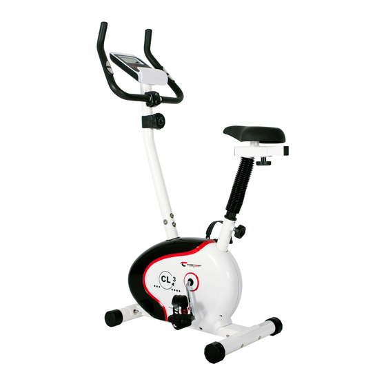
  • Seite 1 Heimsport-Trainingsgerät CL 3 Montage- und Bedienungsanleitung Assembly and exercise instructions for Order No. 1305 für Bestell-Nr. 1305 Montage- en bedieningshandleiding voor Notice de montage et d’utilisation du Bestellnummer 1305 No. de commande 1305...
  • Seite 2: Inhaltsverzeichnis

    Inhaltsübersicht Contents Page 1. Wichtige Empfehlungen und Sicherheitshinweise Seite 2 2. Einzelteileübersicht Seite 3 - 4 3. Stückliste Seite 5 - 6 4. Montageanleitung mit Explosionsdarstellungen Seite 7 - 10 Sommaire Page 5. Benutzung des Gerätes Seite 10 6. Computeranleitung Seite 11 7. Trainingsanleitung Seite 12 Inhoudsopgave Pagina 31 Sehr geehrte Kundin, sehr geehrter Kunde Wir gratulieren Ihnen zum Kauf dieses Heimsport-Trainingsgerätes und wünschen Ihnen viel Vergnügen damit.
  • Seite 5: Stückliste

    Stückliste - Ersatzteilliste Wenn ein Bauteil nicht in Ordnung ist oder fehlt, oder wenn Sie in Zukunft ein Ersatzteil benötigen, wenden Sie sich bitte an uns. CL 3 Best.-Nr. 1305 Adresse: Top-Sports Gilles GmbH Technische Daten: Stand: 01. 10. 2013 Friedrichstr.
  • Seite 6 Abbildungs- Bezeichnung Abmessung Menge Montiert an ET-Nummer Stück Abbildungs Nr. Unterlegscheibe 8//16 31+33 36-9962-CR Selbstsichernde Mutter 39-9918-CR Kugellager 30/45 36-9713-02-BT Lageraufnahme 36-9713-01-BT Mutter 36-9713-05-BT Schraube 3x10 39-10127-SW Lagerabdeckung 1 36-9713-06-BT Unterlegscheibe 23//38 36-9713-07-BT Flachriemen 48+56 36-1305-06-BT Tretkurbelscheibe 36-1305-07-BT Achsmutter M10x1 39-9820-SW Schraube M6x50...
  • Seite 7: Montageanleitung Mit Explosionsdarstellungen

    Montageanleitung Entnehmen Sie alle Einzelteile der Verpackung, legen diese auf den Boden und kontrollieren die Vollzähligkeit grob anhand der Montageschritte. Zu beachten ist dabei, dass einige Teile direkt mit dem Grund- gestell verbunden sind und vormontiert wurden. Des Weiteren sind auch einige andere Einzelteile schon zu Einheiten zusam- mengefügt worden.
  • Seite 8 Schritt 3: Montage des Sattels (33) und des Sattelstützrohres (16). 1. Den Sattel (33) mit der Sitzfläche nach unten hinlegen. 2. Die Aufnahmeplatte des Sattelschlittens (34) auf die oben lie- gende Rückseite des Sattels (33) auflegen. Die Gewindestücke auf der Rückseite des Sattels müssen durch die entsprechenden Löcher in der Aufnahmeplatte des Sattelschlitten (34) ragen.
  • Seite 9 Schritt 5: Montage des Lenkers (27) am Lenkerstützrohr (17). 1. Den Lenker (27) zum Lenkerstützrohr (17) führen, und so aus- richten, dass das Lochbild des Lenkers und des Lenkerstützrohr übereinstimmen. Auf die Schrauben (31) jeweils einen Federring (30) und Unter- legscheibe (39) aufstecken und die Schrauben (31) durch die Bohrungen am Lenker führen, in die Gewindelöcher im Stützrohr (17) eindrehen und fest anziehen.
  • Seite 10: Benutzung Des Gerätes

    Schritt 7: Kontrolle 1. Alle Verschraubungen und Steckverbindungen auf ordnungs- gemäße Montage und Funktion prüfen. Die Montage ist hiermit beendet. 2. Wenn alles in Ordnung ist, mit leichten Widerstandseinstellungen mit dem Gerät vertraut machen und die individuellen Einstellun- gen vornehmen. Anmerkung: Bitte das Werkzeug-Set und die Anleitung sorgsam aufbewahren, da diese bei ggf.
  • Seite 11: Computeranleitung

    Computeranleitung für 1305 Achtung: Der mitgelieferte Computer bietet den größten Trainingskomfort. Jeder Zur Pulsmessung müssen die beiden Kontaktflächen der Pulsmessgriff- trainingsrelevante Wert wird in einem entsprechenden Sichtfenster Einheit mit beiden Händen gleichzeitig gegriffen werden. Dabei sollten sich angezeigt. die Kontaktflächen mittig in der Handinnenfläche befinden. Vom Trainingsbeginn an werden die benötigte Zeit, die aktuelle 7.
  • Seite 12: Trainingsanleitung

    Trainingsanleitung Um spürbare körperliche und gesundheitliche Verbesserungen zu erreichen, 4. Motivation müssen für die Bestimmung des erforderlichen Trainingsaufwandes die Der Schlüssel für ein erfolgreiches Programm ist ein regelmäßiges Training. folgenden Faktoren beachtet werden: Sie sollten sich einen festen Zeitpunkt und Platz pro Trainingstag einrichten und sich auch geistig auf das Training vorbereiten. Trainieren Sie nur gut 1. Intensität: gelaunt und halten Sie sich stets Ihr Ziel vor Augen. Bei kontinuierlichem Die Stufe der körperlichen Belastung beim Training muß den Punkt der Training werden Sie Tag für Tag feststellen, wie Sie sich weiterentwickeln normalen Belastung überschreiten, ohne dabei den Punkt der Atemlosigkeit und Ihrem persönlichen Trainingsziel Stück für Stück näher kommen. und /oder der Erschöpfung zu erreichen. Ein geeigneter Richtwert für ein effektives Training kann dabei der Puls sein. Dieser sollte sich während des Trainings in dem Bereich zwischen 70% und 85% des Maximalpulses befinden (Ermittlung und Berechnung siehe Tabelle und Formel).
  • Seite 13: Important Recommendations And Safety Information

    Contents 1. Summary of Parts Page 3 - 4 2. Important Recommendations and Safety Information Page 13 3. Parts List Page 14 - 15 4. Assembly Instructions With Exploded Diagrams Page 16 - 19 5. Mount, Use & Dismount Page 19 6. Computer instructions Page 20 7. Training Instructions Page 21 Dear customer, We congratulate you on your purchase of this home training sports unit and hope that we will have a great deal of pleasure with it. Please take heed of the enclosed notes and instructions and follow them closely concerning assembly and use. Please do not hesitate to contact us at any time if you should have any questions. Top-Sports Gilles GmbH Important Recommendations and Safety Instructions 12.
  • Seite 14: Parts List

    Parts List – Spare Parts List Please contact us if any components are defective or missing, or if you need any spare parts or replacements in future. CL 3 Order No. 1305 Technical data: Issue: 01. 10. 2013 Top-Sports Gilles GmbH Friedrichstr. 55 • Magnetic brake system 42551 Velbert • approx. 7 KG flywheel Telefon: +49 (0) 20 51 - 6 06 70 • 8-manually adjustable load steps Telefax: +49 (0) 20 51 - 6 06 74 4 •...
  • Seite 15 Illustration imensions Quantity Attached to ET number signation illustration No. Washer 8//16 31+33 36-9962-CR Nylon nut 39-9918-CR Ball bearing 30/45 36-9713-02-BT Bearing holder 36-9713-01-BT 36-9713-05-BT Screw 3x10 39-10127-SW Bearing cover 1 36-9713-06-BT Big washer 23//38 36-9713-07-BT Belt 48+56 36-1305-06-BT Belt wheel 36-1305-07-BT Axle nut M10x1...
  • Seite 16: Assembly Instructions With Exploded Diagrams

    Assembly Instructions Remove all the separate parts from the packaging, lay them on the floor and check roughly that all are there on the base of the assembly steps. Please note that a number of parts have been connected directly to the main frame and preassembled. In addition, there are several other individual parts that have been attached to separate units.
  • Seite 17 Step 3: Installation of saddle (33) and saddle support (16). 1. Place the saddle (33) with the seat surface downwards. 2. Place the retaining plate of the saddle slide (34) on the upwards pointing bottom of the saddle (33). The threaded pieces on the bottom of the saddle (33) must project through the corresponding holes in the retaining plate of the saddle slide (34).
  • Seite 18 Step 5: Installation of handlebar (27) at handlebar support (17). 1. Place the handlebar (27) against the handlebar support (17) and adjust so that the hole patterns in the handlebar and the handlebar support are aligned. Put one spring washer (30) and washer (39) on each screw (31).
  • Seite 19: Mount, Use & Dismount

    Step 7: Checks 1. Check the correct installation and function of all screwed and plug connections. Installation is thereby complete. 2. When everything is in order, familiarise yourself with the machine at a low resistance setting and make your individual adjustments. Note: Please keep the tool set and the instructions in a safe place as these may be required for repairs or spare parts orders becoming...
  • Seite 20: Computer Instructions

    Computer instructions for 1305 Keys: 1. „F“ key: Pressing this key once briefly makes it possible to change from one function The supplied computer allows the most convenient training. Every value to another, i.e. the respective functions can be selected for which entries relevant to training is displayed in a corresponding window.
  • Seite 21: Training Instructions

    Training instructions You must consider the following factors in determining the amount of training effort required in order to attain tangible physical and health benefits: 1. Intensity: The level of physical exertion in training must exceed the level of normal exertion without reaching the point of breathlessness and / or exhaustion. A suitable guideline for effective training can be taken from the pulse rate. During training this should rise to the region of between 70% to 85% of the maximum pulse rate (see the table and formular for determination and calculation of this). During the first weeks, the pulse rate should remain at the lower end of this region, at around 70% of the maximum pulse rate. In the course of the follo- wing weeks and months, the pulse rate should be slowly raised to the upper limit of 85% of the maximum pulse rate. The better the physical condition of the person doing the exercise, the more the level of training should be encreased to remain in the region of between 70% to 85% of the maximum pulse rate. This should be done by lengthening the time for the training and / or encreasing the level of difficulty. If the pulse rate is not shown on the computer display or if for safety reasons you wish to check your pulse rate, which could have been displayed wrongly due to error in use, etc., you can do the following: a. Pulse rate measurement in the conventional way (feeling the pulse at the wrist, for example, and counting the number of beats in one minute). b. Pulse rate measurement with a suitable specialised device (available from dealers specialising in health-related equipment). 2.Frequency Most experts recommend a combination of health-conscious nutrition, which must be determined on the basis of your training goal, and physical training three times a week. A normal adult must train twice a week to maintain his...
  • Seite 22 Sommaire 1. Aperçu des pièces Page 2. Recommandations importantes et règles de sécurité Page 3. Nomenclature Page 23 - 24 4. Notice de montage avec écorchés Page 25 - 28 5. Monter, utiliser & descendre Page 6. Manuel d’utilisation du calculateur électronique Page 7.
  • Seite 23: Nomenclature

    Liste des pièces- Liste des pièces de rechange Si une pièce n’est pas correcte, s’il manque une pièce ou si vous avez besoin d’une pièce de rechange à l’avenir, veuillez vous CL 3 N° de commande 1305 adresser à : Caractéristiques techniques :...
  • Seite 24 Schéma Désignation Dimensions Quantité Monté sur Numéro ET n° en mm Unités schéma n° Rondelle 8//16 31+33 36-9962-CR Ecrou autobloquant 39-9918-CR Roulement à billes 30/45 36-9713-02-BT Support de roulement 36-9713-01-BT Ecrou 36-9713-05-BT 3x10 39-10127-SW Pièce de roulement 1 36-9713-06-BT Rondelle 23//38 36-9713-07-BT Câble plat...
  • Seite 25: Notice De Montage Avec Écorchés

    Notice de montage Sortez toutes les pièces de l’emballage, posez-les sur le sol et contrôlez si rien ne manque en vous basant grossièrement sur la étapes de montage. Il faut tenir compte du fait que certaines pièces ont été reliées au cadre et prémontrés. Quelques autres pièces ont également déjà...
  • Seite 26 Etape n° 3: Montage de la selle (33) et du tube support de selle (16). 1. Poser le selle (33) à terre en veillant à ce que la sellerie soit dirigée vers le bas. 2. Placer la plaque d’appui du chariot de selle (34) sur le dos du selle (33) situé...
  • Seite 27 Etape n° 5: Montage du guidon (27) sur le tube support de guidon (17). 1. Diriger le guidon (27) vers le tube support de guidon (17) en veillant à ce que les gabarits des trous du guidon concordent avec ceux du tube support de guidon. Placer une rondelle élastique bombée (30) et une rondelle (39) sur chacune des vis (31).
  • Seite 28: Monter, Utiliser & Descendre

    Etape n° 7: Contrôle 1. Vérifier si les assemblages et connexions ont été effectués cor- rectement et fonctionnent. Le montage est maintenant terminé. 2. Si tout est en ordre, se familiariser avec l’appareil en effectuant de légers réglages de la résistance et effectuer les réglages individuels.
  • Seite 29: Manuel D'utilisation Du Calculateur Électronique

    Mode d’emploi de l’ordinateur 1305 L’ordinateur livré vous offre le plus grand confort d‘entraînement. Chaque Touches : valeur importante pour l’entraînement est affichée dans une fenêtre. Le temps nécessaire, la vitesse actuelle, la consommation de calories 1. Touche „E“: approximative, la distance parcourue et le pouls actuel sont affichés dès le Pour fixer préalablement et par étape des valeurs dans les fonctions commencement de l’entraînement.
  • Seite 30: Recommandations Pour L'entraînement

    Recommandations pour l’entraînement Les facteurs ci-après doivent être pris en compte pour la détermination de l’entraînement indispensable afin d’améliorer concrètement son physique et sa santé: 1. Intensité: L’entraînement n’aura d’effets positifs que si les efforts déployés dépassent ceux de la vie quotidienne, mais sans être hors d’haleine et/ou se sentir épui- sé.
  • Seite 31: Belangrijke Aanbevelingen En Veiligheidsinstructies

    Inhoudsopgave 1. Overzicht van de losse delen pagina 3 - 4 2. Belangrijke aanbevelingen en veiligheidsinstructies pagina 31 3. Stuklijst pagina 32 - 33 4. Montagehandleiding met explosietekeningen pagina 34 - 37 5. Opstappen, Gebruiken & Afstappen pagina 37 6. Handleiding bij de computer pagina 38 7.
  • Seite 32: Stuklijst

    Stuklijst - reserveonderdelenlijst Wanneer een bepaald onderdeel niet in orde is of ontbreekt, of wanneer u in de toekomst een reserveronderdeel nodig heeft, kunt CL 3 best.nr. 1305 u zich wenden tot: Technische specificatie: Stand: 01. 10. 2013 Top-Sports Gilles GmbH • ca. 7 kg vliegwielmassa Friedrichstr. 55...
  • Seite 33 Afbeeldings- Beschrijving Afmetingen Aantal Gemonteerd aan ET-nummer stuks afbeeldingsnr. Onderlegplatje 8//16 31+33 36-9962-CR Zelfborgende moer 39-9918-CR Kogellager 30/45 36-9713-02-BT Lageropname 36-9713-01-BT Moer 36-9713-05-BT Schroef 3x10 39-10127-SW Kogellagerafdekking 1 36-9713-06-BT Onderlegplatje 23//38 36-9713-07-BT Flakke riem 48+56 36-1305-06-BT Pedaalaandrijfschijf 36-1305-07-BT Asmoer M10x1 39-9820-SW Schroef M6x50...
  • Seite 34: Montagehandleiding Met Explosietekeningen

    Montagehandleiding Neem alle losse onderdelen uit de verpakking, leg deze op de grond en bruto controleer aan de hand van de montageen staps of alle onderdelen aanwezig zijn. Hierbij moet er op worden gelet dat een aantal onderdelen rechtstreeks met het onderstel zijn verbonden en voorgemonteerd zijn.
  • Seite 35 Stap 3: Montage van het zadel (33) en de zadelsteunbuis (16). 1. Het zadel (33) met het zitvlak naar onderen neerleggen. 2. De bevestigingsschijf van de zadelglijder (34) op de bovenliggende achterzijde van het zadel (33) bevestigen. De schroefdraadgaten op de achterzijde van het zadel moeten door de betreffende gaten in de bevestigingsschijf van de zadelsteunbuis (16) steken.
  • Seite 36 Stap 5: Montage van het stuur (27) aan de steunbuis (17). 1. De stuur (27) naar de hiervoor voorziene steunbuis (27) leiden en zodanig uitlijnen dat de gaten van de stuurinrichting en van de steunbuis van de stuurinrichting overeenstemmen. De bouten (31) allemaal voorzien van een veerring (30) en een onderlegplaatje (39) door de gaten in de stuurbuis steken, in de schroefdraadgaten van het stuursteunbuis (17) draaien tot ze stevig vastzitten.
  • Seite 37: Opstappen, Gebruiken & Afstappen

    Stap 7: Controle: 1. Alle schroef- en stekkerverbindingen op een correcte montage en juiste werking controleren. Daarmee is de montage beëindigd. 2. Wanneer alles in orde is, met lichte weerstandsinstellingen vertrouwd raken met het apparaat en de individuele instellingen vastzetten. Opmerking: De gereedschapsset en de gebruiksaanwijzing a.u.b.
  • Seite 38: Handleiding Bij De Computer

    Computerhandleiding voor 1305 De bijgeleverde computer zorgt voor een uitstekend trainingscomfort. Elke Toetsen: trainingsrelevante waarde wordt in het venster weergegeven. Vanaf het begin van de training worden de benodigde tijd, de actuele snelheid, het 1. „E“-toets: verbruikte aantal calorieën, de afgelegde afstand en de actuele hartslag Door telkens één keer kort op deze toets te drukken kunnen waarden in de weergegeven.
  • Seite 39: Trainingshandleiding

    Trainingshandleiding De onderstaande factoren moeten in acht worden genomen bij het bepalen van de benodigde training voor het bereiken van een merkbare verbetering van uw figuur en gezondheid: 1. Intensiteit: De mate van lichamelijke belasting bij de training moet de normale belasting overschrijden, zonder dat u daarbij buiten adem en/of uitgeput raakt.
  • Seite 40 Service Bei Reklamationen, notwendigen Ersatzteilbestellungen oder © by Top-Sports Gilles GmbH Reparaturen wenden Sie sich bitte an unsere Service Abteilung. D-42551 Velbert (Germany) Service: Top-Sports Gilles GmbH Tel.: +49 (0)2051/6067-0 Friedrichstrasse 55 info@christopeit-sport.com Fax: +49 (0)2051/6067-44 D - 42551 Velbert http://www.christopeit-sport.com...

Diese Anleitung auch für:

1305

Inhaltsverzeichnis