Werbung
Quicklinks
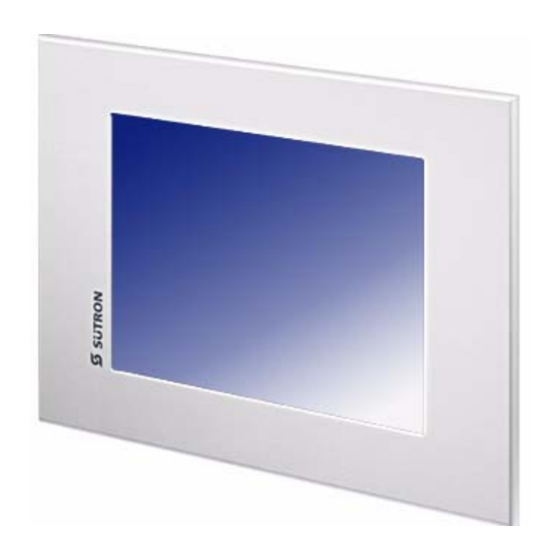
Touch Panel
Sütron electronic GmbH
Kurze Straße 29
70794 Filderstadt
TP(M)104, TP(M)151, TP(M)150
Tel: ++49 7 11 / 77 09 80
Fax: ++49 7 11 / 77 09 86 0
E-Mail: doku@suetron.de
Internet: www.suetron.de
INSTALLATIONSANWEISUNG
INSTALLATION INSTRUCTIONS
(80860.090)
Version: 3
© Copyright by Sütron electronic GmbH
Hinweis
Temperatur- und Feuchtigkeitseinflüsse können zu abweichenden Maßen in der Bohrschablone füh-
ren. Deshalb ist es erforderlich, die Maßhaltigkeit anhand der abgebildeten Maße zu überprüfen.
Beachten Sie unbedingt auch die weiterführenden Informationen im Anwenderhandbuch unter
www.suetron.de/handbuch.
Montage
GEFAHR
Folgende Sicherheitsabstände müssen abhängig von der Displaygröße des Bediengeräts zu einem
Kompass eingehalten werden:
Display <= 7"
Display > 7"
Standardkompass
0,75 m
2,2 m
Steuerkompass
0,45 m
1,35 m
ACHTUNG: Beschädigung
Beim Einbau müssen Sie umlaufend einen Freiraum von mindestens 30 mm berücksichtigen, um eine
ausreichende Luftzirkulation zu gewährleisten.
ACHTUNG: Beschädigung
Beachten Sie bei horizontalem Einbau des Bediengeräts, dass es durch zusätzliche Wärmequellen
unterhalb des Bediengeräts zu einem Hitzestau kommen kann.
Sorgen Sie für eine ausreichende Wärmeableitung!
Beachten Sie für den Betrieb des Geräts den zulässigen Temperaturbereich, der in den technischen
Daten im Anwenderhandbuch angegeben ist.
ACHTUNG: Beschädigung
Um die in den technischen Daten angegebene Schutzart zu gewährleisten, achten Sie unbedingt dar-
auf, dass die Dichtung eben auf der Einbaufläche aufliegt und die Gewindestifte der Montageklam-
mern mit einem Drehmoment von maximal 1 Nm gleichmäßig angezogen sind.
Das Gerät ermöglicht Ihnen eine schnelle und einfache Montage von der Geräterückseite. Vorzugs-
weise wurde hier an den Einbau in Schalttafeln mit einer Blechstärke von ca. 1 mm bis 6 mm gedacht.
1.
Schieben Sie das Gerät von vorne durch den Montageausschnitt.
Montage mit Montageklammer
2.
Setzen Sie die Montageklammern in die dafür vorgesehenen Aussparungen (Punkt 1) und zie-
hen Sie die Klammern bis zur Rastung nach unten (Punkt 2).
3.
Fixieren Sie das Gerät mit den Gewindestiften (Punkt 3).
Note
The influence of temperature and humidity can result in dimensional deviation. Therefore it is neces-
sary to check the dimensional accuracy with the imaged dimensions.
Please note also the detailed information in the user manual at
www.suetron.de/en/manual.
Mounting the Device
DANGER
The following safety distances to a compass must be kept depending on the display size of the ope-
rating device:
Display <= 7"
Display > 7"
Standard compass
0.75 m (29.527")
2.2 m (86.614")
Steering compass
0.45 m (17.716")
1.35 m (53.149")
NOTICE: Damage
When installing the device, leave a gap of at least 30 mm (1.181") around the device to ensure suffi-
cient air circulation.
NOTICE: Damage
When the operating device is installed horizontally, please note that additional sources of heat bene-
ath the operating device may result in heat accumulation.
Make sure to allow sufficient heat dissipation!
Please observe the permissible temperature range specified in the technical data of the user manual
when operating the device.
NOTICE: Damage
In order to ensure the degree of protection specified in the technical data, always make sure that the
seal lies flat against the mounting surface and the threaded pins of the mounting brackets are tighte-
ned uniformly to a maximum torque of 1 Nm.
The operating device can be easily and quickly mounted from the rear of the operating device. This
is particularly recommended for mounting in switchboards with a plate thickness of approx. 1 mm to
6 mm (0.039" to 0.236").
1.
Insert the device in the mounting cutout from the front.
Mounting with mounting brackets
2.
Insert the mounting brackets into the appropriate openings (figure 1) and pull the brackets down-
wards until they lock in place (figure 2).
3.
Fasten the device into position using the threaded pins (figure 3).
TP(M)104:
A
Montageausschnitt / Panel cutout
B
Frontplatte / Front panel
Werbung

Verwandte Anleitungen für Sutron TPM104


Inhaltszusammenfassung für Sutron TPM104
- Seite 1 Note TP(M)104: Touch Panel Sütron electronic GmbH Kurze Straße 29 70794 Filderstadt The influence of temperature and humidity can result in dimensional deviation. Therefore it is neces- TP(M)104, TP(M)151, TP(M)150 Tel: ++49 7 11 / 77 09 80 sary to check the dimensional accuracy with the imaged dimensions. Fax: ++49 7 11 / 77 09 86 0 E-Mail: doku@suetron.de Please note also the detailed information in the user manual at...
- Seite 2 TP(M)151 / TP(M)150: Montageausschnitt / Panel cutout Frontplatte / Front panel...