EVCO EVK411M Anleitung
Quicklinks
Evco S.p.A. • Code 104K411M0L04
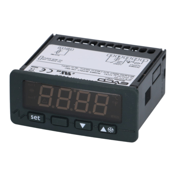
EVK411J/EVK411M
Single output digital thermoregulators for general purposes
GB ENGLISH
• test the working power supply voltage, working electrical frequency
1
GETTING STARTED
and working electrical power of the instrument; they must correspond
1.1 Important
with the local power supply
Read these instructions carefully before installing and using the instru-
• disconnect the local power supply before servicing the instrument
ment and follow all additional information for installation and electrical
• provide the thermocouple with a protection able to protect it against
connection; keep these instructions close to the instrument for future
contacts with metal parts or use insulated thermocouples
consultations.
• do not use the instrument as safety device
1.2 Installing the instrument
• for repairs and information on the instrument please contact Evco
Panel mounting, with click brackets (supplied by the builder); dimen-
sales network.
sions in mm (in).
2
USER INTERFACE
2.1 Turning on/off the instrument
To turn on the instrument you have to supply it; to turn it off it is enough
to cut off the power supply.
2.2 The display
If the instrument is turned on, during the normal operation the display
will show the quantity you have set with parameter P5:
• if P5 = 0, the display will show the room temperature
• if P5 = 1, the display will show the working setpoint.
2.3 Showing the room temperature
• make sure the keyboard is not locked and no procedure is running
• press
• press
To quit the procedure:
DIMENS.
MINIMUM
TYPICAL
MAXIMUM
• press
A
71.0 (2.795)
71.0 (2.795)
71.8 (2.826)
• press
B
29.0 (1.141)
29.0 (1.141)
29.8 (1.173)
2.4 Activating the defrost by hand
• make sure the keyboard is not locked and no procedure is running
• press
If parameter r5 has value 1 (heating action), the defrost functions will
not be enabled.
2.5 Locking/unlocking the keyboard
To lock the keyboard:
• make sure no procedure is running
• press
If the keyboard is locked, you will not be allowed to:
Additional information for installation:
• activate the defrost by hand
• 59.0 (2.322) is the maximum depth with screw terminal blocks
• modify the working setpoint with the procedure related in paragraph
• 83.0 (3.267) is the maximum depth with extractable terminal blocks
4.1 (you also can modify the working setpoint through parameter SP).
• the panel thickness must not be higher than 8.0 mm (0.314 in)
These operations provoke the visualization of the label "Loc" 1 s.
• working conditions (working temperature, humidity, etc.) must be be-
To unlock the keyboard:
tween the limits indicated in the technical data
• press
• do not install the instrument close to heating sources (heaters, hot air
2.6 Silencing the buzzer
ducts, etc.), devices provided with big magnetos (big speakers, etc.),
• make sure no procedure is running
locations subject to direct sunlight, rain, humidity, dust, mechanical
• press a button (the first pressure of the button does not provoke its
vibrations or bumps
usual effect).
• according to the safety legislation, the protection against electrical
3
OPERATION
parts must be ensured by a correct installation of the instrument; the
3.1 Preliminary information
parts that ensure the protection must be installed so that you can not
The operation mainly depends on parameter r5.
3.2 Operation with parameter r5 = 0 (cooling action)
remove them if not by using a tool.
1.3 Wiring diagram
With reference to the wiring diagram:
• terminals 4 and 5 are available only in the models with power supply
230 VAC and 115 VAC; terminals 6 and 7 are available only in the
models with power supply 12 VAC/DC and 12-24 VAC/DC
• the serial port (by request) is the port for the communication with the
supervision system (through a serial interface, via TTL, with MODBUS
communication protocol) or with the programming key; the port must
not be used at the same time for the same purposes.
3.3 Operation with parameter r5 = 1 (heating action)
4
SETTINGS
4.1 Setting the working setpoint
• make sure the keyboard is not locked and no procedure is running
• press
• press
• press
You also can modify the working setpoint through parameter SP .
4.2 Setting configuration parameters
To gain access the procedure:
• make sure no procedure is running
• press
Additional information for electrical connection:
• press
• do not operate on the terminal blocks with electrical or pneumatic
• press
screwers
• press
• if the instrument has been moved from a cold location to a warm one,
• press
the humidity could condense on the inside; wait about an hour be-
To select a parameter:
fore supplying it
• press
To modify a parameter:
• press
• press
or
in 15 s
• press
or do not operate 15 s.
To quit the procedure:
• press
and
4 s or do not operate 60 s.
Switch off/on the power supply of the instrument after the
modification of the parameters.
4.3 Restoring the default value of configuration param-
eters
• make sure no procedure is running
• press
and
4 s: the display will show "PA"
• press
• press
or
in 15 s to set "743"
• press
or do not operate 15 s
• press
and
4 s: the display will show "dEF"
• press
• press
or
in 15 s to set "149"
• press
or do not operate 15 s: the display will show "dEF" flash-
ing 4 s, after which the instrument will quit the procedure
2 s: the display will show "Pb1"
• switch off/on the power supply of the instrument.
Make sure the default value of the parameters is appropri-
ate, in particular if the probes are not J thermocouples.
or do not operate 60 s
5
SIGNALS
or
as long as the display shows the quantity you have
5.1 Signals
set with parameter P5 or do not operate 60 s.
LED
MEANING
out 1
LED load
if it is lit, the load will be turned on
4 s.
if it flashes:
• the modification of the working setpoint will be running
• a load protection will be running (parameters C1 and C2)
LED defrost
if it is lit, the defrost will be running
LED alarm
and
2 s: the display will show "Loc" 1 s.
if it is lit, an alarm will be running
°C
LED Celsius degree
if it is lit, the unit of measure of the temperatures will be
Celsius degree (parameter P2)
°F
LED Fahrenheit degree
if it is lit, the unit of measure of the temperatures will be
Fahrenheit degree (parameter P2)
and
2 s: the display will show "UnL" 1 s.
CODE
MEANING
Loc
the keyboard and/or the working setpoint are locked (pa-
rameter r3); also look at paragraph 2.5
6
ALARMS
6.1 Alarms
CODE
MEANING
AL1
First temperature alarm
Remedies:
• check the room temperature
• look at parameters A1 and A3
Effects:
• no effect
AL2
Second temperature alarm
Remedies:
• check the room temperature
• look at parameters A5 and A7
Effects:
• no effect
When the cause that has provoked the alarm disappears, the instru-
ment restores the normal operation.
7
INTERNAL DIAGNOSTICS
7.1 Internal diagnostics
CODE
MEANING
Pr1
Room probe error
Remedies:
• look at parameter P0
• check the integrity of the probe
• check the connection instrument-probe
• check the room temperature
Effects:
• the load activity will depend on parameters C4 and C5
When the cause that has provoked the alarm disappears, the instru-
ment restores the normal operation.
8
TECHNICAL DATA
8.1 Technical data
LED out 1 will flash
Box: self-extinguishing grey.
or
in 15 s; also look at parameters r1, r2 and r3
Frontal protection: IP 65.
or do not operate 15 s.
Connections (use copper conductors only): screw terminal blocks
(power supply, input and output), 6 poles connector (serial port; by
request); ext. terminal blocks (power sup., input and output) by request.
Working temperature: from 0 to 55 °C (32 to 131 °F , 10 ... 90% of
relative humidity without condensate).
and
4 s: the display will show "PA"
Power supply: 230 VAC, 50/60 Hz, 3 VA (approximate); 115 VAC or
12-24 VAC/DC or 12 VAC/DC by request.
Insulation class: 2.
or
in 15 s to set "-19"
or do not operate 15 s
Alarm buzzer: by request.
and
4 s: the display will show "SP".
Measure inputs EVK411J: 1 (room probe) for J/K thermocouples.
Measure inputs EVK411M: 1 (room probe) for PTC/NTC probes,
or
J/K thermocouples, 2/3 wires Pt 100, Pt 1000 and Ni 120 probes,
0-20/4-20 mA and 0-10/2-10 V transducers (universal measure input).
Working range: from -50 to 150 °C (-50 to 300 °F) for PTC probe,
2.4 Manuelle Aktivierung des Abtauvorgangs
from -40 to 110 °C (-40 to 230 °F) for NTC probe, from -100 to 800 °C
• Sicherstellen, dass die Tastatur nicht gesperrt und kein Vorgang aktiv
(-140 to 1,450 °F) for J thermocouple, from -100 to 1,300 °C
ist.
(-140 to 1,999 °F) for K thermocouple, from -200 to 650 °C
• Die Taste
(-320 to 1,200 °F) for 2/3 wires Pt 100 probe, from -200 to 650 °C
Ist der Parameter r5 auf 1 eingestellt (Heizbetrieb), werden die Abtauf-
(-320 to 1,200 °F) for 2/3 wires Pt 1000 probe, from -80 to 300 °C
unktionen nicht aktiviert.
(-110 to 570 °F) for 2/3 wires Ni 120 probe.
2.5 Sperren / Entsperren der Tastatur
Resolution: 0.1 °C/1 °C/1 °F .
Sperren der Tastatur:
Digital outputs:1 relay:
• Sicherstellen, dass kein Vorgang aktiv ist
• load relay: 16 res. A @ 250 VAC, 5 FLA, 30 LRA
• Die Tasten
(change-over contact).
The maximum current allowed on the load is 10 A.
Bei gesperrter Tastatur ist es nicht möglich:
Serial port: port for the communication with the supervision system
• den Abtauvorgang manuell zu aktivieren;
(through a serial interface, via TTL, with MODBUS communication pro-
• den Betriebssollwert mit dem unter Punkt 4.1 beschriebenen Verfah-
tocol) or with the programming key; by request.
ren zu ändern (der Betriebssollwert kann auch mit dem Parameter SP
eingestellt werden).
D DEUTSCH
Bei dem Versuch, diese Operationen bei gesperrter Taststur auszufüh-
1
VORBEREITUNG
ren, wird auf dem Display für 1 s "Loc" angezeigt.
1.1 Wichtig
Entsperren der Tastatur:
Diese Anleitung vor der Installation und Inbetriebnahme bitte aufmerk-
• Die Tasten
sam lesen und alle Hinweise zur Installation und zum elektrischen An-
schluss beachten. Die Anleitung zum späteren Nachschlagen aufbe-
2.6 Stummstellen des Summers
wahren.
• Sicherstellen, dass kein Vorgang aktiv ist.
1.2 Installation
• Eine Taste drücken (das erste Betätigen der Taste löst nicht die zuge-
Auf Platte mit mitgelieferten Schnappbügeln (siehe Zeichnungen unter
wiesene Funktion aus).
Punkt 1.2 der Anleitung in englischer Sprache).
3
BETRIEB
3.1 Vorbemerkung
Hinweise zur Installation:
• 59,0 ist die maximale Tiefe mit verschraubten Klemmleisten.
Der Betriebsmodus hängt vor allem von der Einstellung des Parameters
• 83,0 ist die maximale Tiefe mit ausziehbaren Klemmleisten.
r5 ab.
• Die Stärke der Platte darf 8,0 mm nicht überschreiten.
3.2 Betrieb mit Parameter r5 = 0 (Kühlbetrieb)
• Sicherstellen, dass die Betriebsbedingungen (Betriebstemperatur, Luft-
Siehe Zeichnung unter Punkt 3.2 der Anleitung in englischer Sprache.
feuchte usw.) innerhalb der in den technischen Daten aufgeführten
3.3 Betrieb mit Parameter r5 = 1 (Heizbetrieb)
Grenzen liegen.
Siehe Zeichnung unter Punkt 3.3 der Anleitung in englischer Sprache.
• Das Gerät nicht in der Nähe von Hitzequellen (Widerständen, Heißluft-
4
EINSTELLUNGEN
leitungen usw.), Geräten mit starken Magneten (großen Lautsprechern
4.1 Einstellung des Betriebssollwertes
usw.) sowie nicht an Orten mit direkten Witterungseinflüssen wie
• Sicherstellen, dass die Tastatur nicht gesperrt und kein Vorgang aktiv
Sonneneinstrahlung, Regen, Feuchtigkeit, Staub oder mechanischen
ist.
Schwingungen bzw. Stößen installieren.
• Die Taste
• Entsprechend den Sicherheitsbestimmungen muss der Schutz vor even-
• Innerhalb von 15 s die Taste
tuellen Kontakten mit elektrischen Komponenten durch eine korrekte
Parameter r1, r2 und r3
Installation des Geräts sichergestellt werden. Alle Schutzvorrichtungen
•
drücken oder für 15 s keine Taste betätigen.
sind so zu befestigen, dass sie ohne Einsatz von Wekzeug nicht ent-
Der Betriebssollwert kann auch mit dem Parameter SP . eingestellt wer-
fernt werden können.
den
1.3 Elektrischer Anschluss
4.2 Einstellung der Konfigurationsparameter
Siehe hierzu Zeichnung 1.3 der Anleitung in englischer Sprache.
Start des Verfahrens:
Mit Bezug auf die elektrischen Schaltpläne:
• Sicherstellen, dass kein Vorgang aktiv ist.
• Die Klemmen 4 und 5 sind nur bei den Modellen mit Spannungs-
• Die Tasten
versorgung von 230 V AC und 115 V AC verfügbar; die Klemmen 6
wird "PA" angezeigt.
und 7 sind nur bei den Modellen mit Spannungsversorgung von 12 V
•
drücken.
AC/DC und 12-24 V AC/DC verfügbar.
• Innerhalb von 15 s
• Der serielle Port (auf Anfrage) ist die Schnittstelle zur Kommunikation
•
drücken oder für 15 s keine Taste betätigen.
mit dem Überwachungssystem (serieller Port, mit TTL und über das
• Die Tasten
Kommunikationsprotokoll MODBUS) oder dem Programmierschlüssel.
angezeigt.
Der Port darf nicht gleichzeitig für beide Zwecke verwendet werden.
Auswahl eines Parameters:
Hinweise zum elektrischen Anschluss:
•
oder
• An den Klemmleisten nicht mit elektrischen oder pneumatischen
Ändern eines Parameters:
Schraubern arbeiten.
•
drücken.
• Bei Transport des Geräts von einem kalten an einen warmen Ort kann
• Innerhalb von 15 s
im Inneren Feuchtigkeit kondensieren. In diesem Fall vor dem Anle-
•
drücken oder für 15 s keine Taste betätigen.
gen von Spannung eine Stunde warten.
Verlassen des Programmiermodus:
• Sicherstellen, dass die Betriebsspannung, die Frequenz und der Betriebs-
• Die Tasten
strom des Geräts denen des lokalen Netzes entsprechen.
betätigen.
• Das Gerät vor jedem Wartungseingriff von der Spannungsversorgung
Nach Änderungen an den Parametern das Gerät von der
trennen.
Spannungsversorgung trennen.
• den Fühler mit einer Schutzvorrichtung ausstatten, die in der Lage ist,
4.3 Wiederherstellung
diese gegen eventuelle Kontakte mit Metallteilen zu isolieren, oder
Konfigurationsparameter
isolierte Fühler verwenden.
• Sicherstellen, dass kein Vorgang aktiv ist.
• Das Gerät nicht als Sicherheitsvorrichtung verwenden.
• Die Tasten
• Für Reparaturen und Informationen zum Gerät wenden Sie sich bitte
angezeigt.
an das Evco-Vertriebsnetz.
•
drücken.
2
BENUTZERSCHNITTSTELLE
• Innerhalb von 15 s
2.1 Ein- und Ausschalten des Geräts
•
drücken oder für 15 s keine Taste betätigen.
Zum Einschalten das Gerät mit Spannung versorgen, zum Ausschalten
• Die Tasten
die Spannungsversorgung trennen.
angezeigt.
2.2 Display
•
drücken.
Wenn das Gerät eingeschaltet ist, zeigt das Display bei Normalbetrieb
• Innerhalb von 15 s
den mit Parameter P5 eingestellten Wert an:
•
drücken oder für 15 s keine Taste betätigen: Auf dem Display
• Wenn P5 = 0, zeigt das Display die Umgebungstemperatur an.
blinkt für 4 s die Anzeige "dEF", anschließend wird der Modus
• Wenn P5 = 1, zeigt das Display den Betriebssollwert an.
verlassen.
2.3 Anzeige der Umgebungstemperatur
• Das Gerät von der Spannungsversorgung trennen.
• Sicherstellen, dass die Tastatur nicht gesperrt und kein Vorgang aktiv
Sicherstellen, dass der Defaultwert der Parameter zweck-
mäßig ist, insbesondere prüfen, ob die Fühler vom Typ Ther-
ist.
• Die Taste
für 2 s drücken: auf dem Display wird "Pb1" ange-
moelement "J" sind.
zeigt
5
ANZEIGEN
•
drücken.
5.1 Betriebsanzeigen
Beenden des Vorgangs:
LED
•
drücken oder für 60 s keine Taste betätigen.
out 1
•
oder
gedrückt halten, bis das Display die mit dem Parame
ter P5 eingestellten Wert anzeigt oder für 60 s keine
Taste betätigen.
LED Abtauvorgang
Wenn eingeschaltet, läuft ein Abtauvorgang.
Alarm-LED
für 4 s gedrückt halten.
Wenn eingeschaltet, ist ein Alarm aktiv.
°C
LED Grad Celsius
Wenn eingeschaltet, ist die Maßeinheit der Temperatur auf
Grad Celsius eingestellt (Parameter P2).
°F
LED Grad Fahrenheit
Wenn eingeschaltet, ist die Maßeinheit der Temperatur auf
und
für 2 s drücken: Auf dem Display wird für
Grad Fahrenheit eingestellt (Parameter P2).
1 s "Loc" angezeigt.
CODE
BEDEUTUNG
Loc
Tastatur und/oder Betriebssollwert gesperrt (Parameter r3,
siehe Punkt 2.5)
6
ALARME
6.1 Alarme
CODE
BEDEUTUNG
AL1
Erster Temperaturalarm
Behebung:
• Umgebungstemperatur prüfen.
und
für 2 s drücken: Auf dem Display wird für
• Siehe Parameter A1 e A3.
1 s "UnL" angezeigt.
Folgen:
• Das Gerät arbeitet normal weiter.
AL2
Zweiter Temperaturalarm
Behebung:
• Umgebungstemperatur prüfen.
• Siehe Parameter A5 und A7.
Folgen:
• Das Gerät arbeitet normal weiter.
Sobald die Ursache, die den Alarm ausgelöst hat, behoben ist, wird der
Normalbetrieb wieder aufgenommen.
7
INTERNE DIAGNOSE
7.1 Interne Diagnose
CODE
BEDEUTUNG
Pr1
Fehler Umgebungstemperaturfühler
Behebung:
• Siehe Parameter P0.
• Korrekte Funktion des Fühlers prüfen.
drücken: die LED out 1 beginnt zu blinken.
• Verbindung zwischen gerät und Fühler überprüfen.
oder
drücken, siehe auch
• Umgebungstemperatur überprüfen.
Folgen:
• Abnehmerbetrieb hängt von den Parametern C4 und C5
ab.
Sobald die Ursache, die den Alarm ausgelöst hat, behoben ist, wird der
Normalbetrieb wieder aufgenommen.
8
TECHNISCHE DATEN
8.1 Technische Daten
und
für 4 Sekunden drücken: Auf dem Display
Gehäuse: selbstlöschend, grau.
Schutzgrad Frontseite: IP 65.
Anschlüsse (Einzige in Kupfer Leit): Schraubklemmleisten
oder
drücken, um "-19" einzustellen.
(Spannungsversorgung, Eingang und Ausgang), 6-poliger Verbinder
(serieller Port); herausziehbare Klemmleisten (Spannungsversorgung,
und
für 4 s drücken: Auf dem Display wird "SP"
Eingang und Ausgang) auf Anfrage.
Betriebstemperatur: 0 bis 55 °C (10 ... 90% relative Feuchte, nicht
kondensierend).
drücken.
Spannungsversorgung: 230 VCA, 50/60 Hz, 3 VA (Näherungswer-
te); 115 V AC oder 12-24 V AC/DC oder 12 V AC/DC auf Anfrage.
Isolationsklasse: 2.
oder
drücken.
Alarmsummer: auf Anfrage.
Messeingänge EVK411J: 1 (Umgebungstemperaturfühler) Thermo-
element J/K.
und
für 4 s drücken oder für 60 s keine Taste
Messeingänge EVK411M: 1 (Umgebungstemperaturfühler) für
PTC-/NTC-Sonden, Thermoelement J/K, Pt 100, Pt 1000 zwei/dreiadrige
Ni 120 Sonden, Messumformer 0-20/4-20 mA und 0-10/2-10 V (univer-
saler Messeingänge).
der
Default-Werte
der
Messbereich: -50 bis 150 °C bei PTC-Fühlern, -40 bis 110 °C bei NTC-
Fühlern, -100 bis 800 °C bei Thermoelement J, -100 bis
1.300 °C bei Thermoelement K, -200 bis 650 °C bei Pt 100 zwei/drei-
und
für 4 s drücken: Auf dem Display wird "PA"
adrige Sonden, -200 bis 650 °C bei Pt 1000 zwei/dreiadrige Sonden,
-80 bis 300 °C bei Ni 120 zwei/dreiadrige Sonden.
Auflösung: 0,1 °C/1 °C/1 °F .
oder
drücken, um "743" einzustellen.
Digitalausgänge: 1 Relais:
• Abnehmerrelais: 16 A bei 250 V AC, 5 FLA,
und
für 4 s drücken: Auf dem Display wird "dEF"
30 LRA (Wechselkontakt).
Der zulässige Maximalstrom am Abnehmer beträgt 10 A.
Serieller Port: Schnittstelle für die Kommunikation mit dem
oder
drücken, um "149" einzustellen.
Überwachungssystem (über den seriellen Port, mit TTL und dem
Kommunikationsprotokoll MODBUS) oder dem Programmierschlüssel
(auf Anfrage).
BEDEUTUNG
LED Abnehmergerät
Wenn eingeschaltet, ist das Abnehmergerät aktiv.
Wenn blinkend:
• Änderung des Betriebssollwertes im Gange
• Ladeschutz (Parameter C1 und C2)
version 1.04

Verwandte Anleitungen für EVCO EVK411M


Inhaltszusammenfassung für EVCO EVK411M
- Seite 1 (-110 to 570 °F) for 2/3 wires Ni 120 probe. 2.5 Sperren / Entsperren der Tastatur Grad Celsius eingestellt (Parameter P2). 1.2 Installing the instrument • for repairs and information on the instrument please contact Evco modification of the parameters. Resolution: 0.1 °C/1 °C/1 °F . Sperren der Tastatur: °F...
- Seite 2 Evco does not take any responsibility about damages coming by the non-observance of the additional information. info@evco.it • www.evco.it Evco reserves the right to make any change without prior notice and at any time without prejudice the basic safety and operating features.