ROBBE Robin DR 400 ARF Montage- Und Bedienungsanleitung

Verwandte Anleitungen für ROBBE Robin DR 400 ARF


Inhaltszusammenfassung für ROBBE Robin DR 400 ARF
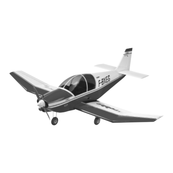
- Seite 1 Montage- und Bedienungsanleitung Assembly and operating instructions Notice de montage et d´utilisation Robin DR 400 ARF No. 3048...
- Seite 2 Vielen Dank, daß Sie sich für dieses robbe Produkt entschie- Robin is an ARF (Almost Ready to Fly) kit, i.e. the model’s com- Merci d’avoir choisi ce produit de la marque robbe. Cette boîte den haben. Hierbei handelt es sich um einen ARF- (Almost ponents are completely factory-built and covered.
- Seite 3 Bauanleitung, Assembly instructions, Notice de montage Robin DR 400 ARF 3048 Hinweis zur Stückliste: n.e. = nicht enthalten Notes on the parts list: N.I. = not included Remarque concernant la liste des pièces: n.c. = non contenu Hinweise zur Fernsteueranlage Radio control equipment Orientieren Sie sich vor Baubeginn über die Einbaumöglichkeit...
- Seite 4 Bauanleitung, Assembly instructions, Notice de montage Robin DR 400 ARF 3048 Bild 2 Fig. 2 Fig. 2 - Die Servodeckel für - Remove the flap servo well covers 1.2 - Retirer les couvercles de servo 1.2 des Landeklappenservos abnehmen. from the wing.
- Seite 5 Bauanleitung, Assembly instructions, Notice de montage Robin DR 400 ARF 3048 Baustufe 2, die Tragfläche Stage 2, the wing Stade 2, l’aile Bezeichnung, Maße in mm Stück Description, size in mm No. off n° désignation, cotes en mm nbre de pièces...
- Seite 6 Bauanleitung, Assembly instructions, Notice de montage Robin DR 400 ARF 3048 Bild 8 Fig. 8 Fig. 8 - Die Deckel wieder aufsetzen. Die - Place the well covers over the servo - Remettre les couvercles en place. Auflageleisten mit Ø 1,5 mm nach den wells.
- Seite 7 Bauanleitung, Assembly instructions, Notice de montage Robin DR 400 ARF 3048 Bild 11 Fig. 11 Fig. 11 - Beide Landeklappenservos mit der - Move both flap servos to the “flaps - À l’aide de l’ensemble de radiocom- Fernsteuerung in die Endstellung retracted”...
- Seite 8 Bauanleitung, Assembly instructions, Notice de montage Robin DR 400 ARF 3048 Bild 14 Fig. 14 Fig. 14 - Die Ruderhornposition - Mark the position of the horns on the - Marquer la position des guignols sur Landeklappen anzeichnen und Löcher flaps and drill the holes 2.5 mm Ø.
- Seite 9 Bauanleitung, Assembly instructions, Notice de montage Robin DR 400 ARF 3048 Bild 18 Fig. 18 Fig. 18 - Wenn gewünscht, können - The aileron servos can be removed at - Si vous le souhaitez, vous pouvez Querruderservos ausgebaut werden. this point if you prefer.
- Seite 10 Bauanleitung, Assembly instructions, Notice de montage Robin DR 400 ARF 3048 Bild 22 Fig. 22 Fig. 22 - Querruderservos wieder einbauen, - Install the aileron servos again and run - Remonter les servos d’aileron, amener Kabel bis zum Klappenschacht führen.
- Seite 11 Bauanleitung, Assembly instructions, Notice de montage Robin DR 400 ARF 3048 Baustufe 3, die Leitwerke Stage 3, the tail panels Stade 3, les empennages Bezeichnung, Maße in mm Stück Description, size in mm No. off n° désignation, cotes en mm nbre de pièces...
- Seite 12 Bauanleitung, Assembly instructions, Notice de montage Robin DR 400 ARF 3048 Bild 27 Fig. 27 Fig. 27 - Das Höhenleitwerk aufkleben, erneut - Glue the tailplane to the fuselage, - Coller le stabilisateur, l’aligner et le ausrichten und Klebstoff trocknen las- check alignment with the wing once centrer et laisser sécher la colle.
- Seite 13 Bauanleitung, Assembly instructions, Notice de montage Robin DR 400 ARF 3048 Bild 31 Fig. 31 Fig. 31 - Das Seitenleitwerk einkleben, recht- - Glue the fin in place, set it exactly at - Coller la dérive verticalement sur le sta- winklig zum Höhenleitwerk ausrichten...
- Seite 14 Bauanleitung, Assembly instructions, Notice de montage Robin DR 400 ARF 3048 Bild 35 Fig. 35 Fig. 35 - Den Übergang aufsetzen, möglichst - Place the fairing in position and trim it - Mettre le passage en place, l’ajuster de spaltfrei anpassen. Schnittkanten ver- carefully to remove any gaps.
- Seite 15 Bauanleitung, Assembly instructions, Notice de montage Robin DR 400 ARF 3048 Bild 38 Fig. 38 Fig. 38 3.12 3.13, 3.14 - Löcher gemäß Markierungen in die - Drill holes at the marked points in the - Percer les trous en fonction des Ruderflächen bohren, Ruderhörner...
- Seite 16 Bauanleitung, Assembly instructions, Notice de montage Robin DR 400 ARF 3048 Bild 41 Fig. 41 Fig. 41 3.19 - Gestängekupplungen 3.19 je an einem - Mount the pushrod connectors 3.19 on - Monter les accouplements de tringle beschnittenen Kreuzhebel two of the prepared output arms (one 3.19 chaque fois à...
- Seite 17 Bauanleitung, Assembly instructions, Notice de montage Robin DR 400 ARF 3048 Baustufe 4, Vorbereiten des Rumpfkopfs Stage 4, preparing the fuselage nose Stade 4, préparatifs au nez du fuselage Bezeichnung, Maße in mm Stück Description, size in mm No. off n°...
- Seite 18 Bauanleitung, Assembly instructions, Notice de montage Robin DR 400 ARF 3048 Bild 47 Fig. 47 Fig. 47 - Die Motorträger 4.11 mit Schrauben - Fix the motor mount 4.11 to the nose - Visser les supports-moteur 4.11 avec 4.8, Fächerscheiben bulkhead using the screws 4.8, serrat-...
- Seite 19 Bauanleitung, Assembly instructions, Notice de montage Robin DR 400 ARF 3048 Bilder 48 und 49 Figs. 48 and 49 Fig. 48 et 49 - Die Radachse 5.1 mit der Distanzhülse - Fit the spacer sleeve 5.2 on the wheel - Munir l’axe de roue 5.1 des manchons 5.2 versehen.
- Seite 20 Bauanleitung, Assembly instructions, Notice de montage Robin DR 400 ARF 3048 Bilder 52 und 53 Figs. 52 and 53 Fig. 52 et 53 - Bugfahrwerk mit Hebel und Mutter - Install the noseleg assembly, complete - Mettre l’atterrisseur avant en place 5.10 einsetzen.
- Seite 21 Bauanleitung, Assembly instructions, Notice de montage Robin DR 400 ARF 3048 Bilder 55 und 56 Figs. 55 and 56 Fig. 55 et 56 5.16 - Den Tankverschluß 5.11 mit den - Hold the circular end-plates 5.12 / 5.13 - Munir le bouchon du réservoir 5.11 des 5.17...
- Seite 22 Bauanleitung, Assembly instructions, Notice de montage Robin DR 400 ARF 3048 Baustufe 6, Kabine und Verbrennungsmotor Stage 6, cabin and motor Stade 6, la cabine et le moteur thermique Bezeichnung, Maße in mm Stück Description, size in mm No. off n°...
- Seite 23 Bauanleitung, Assembly instructions, Notice de montage Robin DR 400 ARF 3048 Bild 61 Fig. 61 Fig. 61 - Den Überstand des Cockpiteinsatzes - Cut away the excess cockpit insert - Poncer les arêtes en saillie du cockpit bündig zum Kopfspant wegschneiden.
- Seite 24 Bauanleitung, Assembly instructions, Notice de montage Robin DR 400 ARF 3048 Bild 64 Fig. 64 Fig. 64 - Die Haube aufsetzen, - Place the canopy on the fuselage, - Mettre la verrière de cabine en place, Cockpiteinsatz ausrichten und mit align it carefully with the cockpit insert l’ajuster par rapport au cockpit et la...
- Seite 25 Bauanleitung, Assembly instructions, Notice de montage Robin DR 400 ARF 3048 Bilder 67 und 68 Figs. 67 and 68 Fig. 67 et 68 - Zum ermittelten Maß 3 mm hinzuad- - Add 3 mm to the measured dimension; - À la cote déterminée, ajouter 3 mm...
- Seite 26 Bauanleitung, Assembly instructions, Notice de montage Robin DR 400 ARF 3048 Bild 71 Fig. 71 Fig. 71 - Gasgestänge von vorn einschieben, - Slip the throttle pushrod into its sleeve - Engager la tringle des gaz par l’avant, den Gabelkopf im Vergaser einhän- from the front and connect the clevis to accrocher la chape au carburateur.
- Seite 27 Bauanleitung, Assembly instructions, Notice de montage Robin DR 400 ARF 3048 Bild 73 Fig. 73 Fig. 73 - Das Kabel des Power-Packs 7.1 auf - Extend the connecting lead attached to - Rallonger le cordon de l’alimentation eine Gesamtlänge von ca. 50 cm ver- the receiver battery 7.1 to a total length...
- Seite 28 Bauanleitung, Assembly instructions, Notice de montage Robin DR 400 ARF 3048 Bild 77 Fig. 77 Fig. 77 - The receiving system switch 7.5 can - Den Schalter 7.5 entweder in der lin- - Monter l’interrupteur 7.5 soit dans la ken Rumpfseitenwand oder in der either be installed in the left-hand fuse- paroi latérale gauche du fuselage soit...
- Seite 29 Bauanleitung, Assembly instructions, Notice de montage Robin DR 400 ARF 3048 Fig. 80 Bild 80 Fig. 80 - Pack the receiver in foam rubber and - Envelopper le récepteur dans de la - Den Empfänger mit Schaumgummi install it in the fuselage. Thread the umwickeln und im Rumpf platzieren.
- Seite 30 Bauanleitung, Assembly instructions, Notice de montage Robin DR 400 ARF 3048 Fig. 82 et 83 Bilder 82 und 83 Figs. 82 and 83 - Die Motorhaube passenden - Cut openings in the motor cowl to clear - Munir le capot-moteur des dégage- ments appropriés au moteur et à...
- Seite 31 Bauanleitung, Assembly instructions, Notice de montage Robin DR 400 ARF 3048 Erforderliches Trimmblei so fixieren, If you have to use ballast, be sure to fix Fixer le plomb de lestage de telle sorte daß es während des Fluges nicht ver- it securely so that there is no chance of qu’il ne puisse se déplacer pendant le...
- Seite 32 Bauanleitung, Assembly instructions, Notice de montage Robin DR 400 ARF 3048 - Die Ausschlaggrößen der Ruder nach Maßangaben einstel- stick movement), correct it using the servo reverse facility course des servos appropriée sur l’émetteur. len. provided by your transmitter. - Ruderausschlag zu klein: Gestänge am Ruderhorn weiter - Set the control surface travels to the values stated in Fig.
- Seite 33 Bauanleitung, Assembly instructions, Notice de montage Robin DR 400 ARF 3048 Test-flying - À noter : pour les travaux de montage, de réglage et de Einfliegen maintenance, ne jamais approcher les mains du plan de - Vor dem Erstflug die Abschnitte „Routineprüfungen vor dem - Before flying the model for the first time please read the sec- rotation de l’hélice –...
- Seite 34 - Check once more that the system operates correctly. Fig. 88 le dispositif de remorquage ouvert. geöffnete Schleppkupplung. shows the tow-release mechanism in the “open” position. robbe Modellsport GmbH & Co. KG robbe Modellsport GmbH & Co. KG robbe Modellsport GmbH & Co. KG Sous réserve de modifications techniques.
- Seite 35 Bauanleitung, Assembly instructions, Notice de montage Robin DR 400 ARF 3048 9.2, 9.3 50 mm 50 mm “N” “N” M 1:1 Scale 1:1 Échelle 1...
- Seite 36 Sous réserve de d’erreur et de modification technique. Copyright robbe-Modellsport 2003 Copie et reproduction, même d’extraits, interdites sans autorisation écrite expresse de la Société robbe-Modellsport GmbH & Co. KG robbe Modellsport GmbH & Co. KG Metzloserstr. 36 Telefon: 06644 / 87-0...