Electro-Voice CPS2.4 Bedienungsanleitung
Inhaltsverzeichnis
Verfügbare Sprachen
Verfügbare Sprachen
Quicklinks
Inhaltsverzeichnis

Verwandte Anleitungen für Electro-Voice CPS2.4


Inhaltszusammenfassung für Electro-Voice CPS2.4
- Seite 1 OWNER’S MANUAL BEDIENUNGSANLEITUNG...
- Seite 17 CONTRACTOR PRECISION SERIES Owner‘s Manual...
- Seite 18 WICHTIGE SICHERHEITSHINWEISE Das Blitzsymbol innerhalb eines gleichseitigen Dreiecks soll den Anwender auf nicht isolierte Lei- tungen und Kontakte im Geräteinneren hinweisen, an denen hohe Spannungen anliegen, die im Fall einer Berührung zu lebensgefährlichen Strom- schlägen führen können. Das Ausrufezeichen innerhalb eines gleichseitigen Dreiecks soll den Anwender auf wichtige Bedie- nungs- sowie Servicehinweise in der zum Gerät gehörenden Literatur aufmerksam machen.
-
Seite 19: Einführung
CONTRACTOR PRECISION SERIES 1 Einführung 1.1 Willkommen Vielen Dank, dass Sie sich für eine Endstufe der Electro-Voice Contractor Precision Serie entschieden haben. Bitte lesen Sie diese Bedienungsanleitung aufmerksam durch, damit Sie Ihren neuen Electro-Voice Verstärker optimal nutzen können. 1.2 Auspacken und Inspektion Öffnen Sie die Verpackung und entnehmen Sie die Endstufe. -
Seite 20: Installation
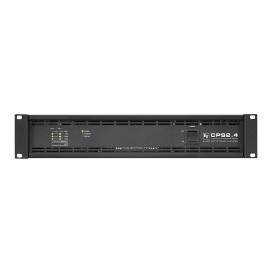
CONTRACTOR PRECISION SERIES 2 Installation 2.1 Bedienelemente, Anzeigen und Anschlüsse Frontseite Pegelanzeigen für Kanäle 1 und 2 Anzeige Schutzschaltung (PROTECT) Anzeige Stummschaltung (MUTE) für Kanäle 1 und 2 Anzeige Betrieb (POWER) Anzeige Standby (STANDBY) Anzeige Remote Amplifier (IRIS-Net) Netzschalter Rückseite Netzeingang Schalter Groundlift (CIRCUIT ⊥... -
Seite 21: Betriebsspannung
Hilfe von Käfigmuttern und Befestigungsschrauben. Geeignete Rackwinkel sind als Zubehör erhältlich. 2.5 Kühlung Bei allen lüftergekühlen Endstufen von Electro-Voice strömt die Luft von der Frontseite zur Rückseite, da kühle Frischluft eher außerhalb des Racks zur Verfügung steht als innerhalb. Die Endstufe bleibt kühler und die entstehende Abwärme kann gezielter abgeführt werden. -
Seite 22: Groundlift
CONTRACTOR PRECISION SERIES ACHTUNG: Die Lüftungsöffnungen der Endstufe dürfen nicht blockiert/verschlossen werden. Bei fehlen- der Kühlung kann sich die Endstufe automatisch abschalten. Halten Sie alle Lüftungsöffnun- gen frei von Staubablagerungen, die den Luftstrom behindern würden. Betreiben Sie die Endstufe nicht in der Nähe von Wärmequellen wie Heizlüftern, Öfen oder an- deren Geräten, die Hitze abstrahlen. -
Seite 23: Betriebsart (Mode) Und Verkabelung Des Audio-Ausgangs
CONTRACTOR PRECISION SERIES 2.9 Betriebsart (MODE) und Verkabelung des Audio-Ausgangs Der Schalter MODE an der Rückseite bestimmt die Betriebsart der Endstufe. Mögliche Schalterstellungen sind DUAL, PARALLEL und BRIDGED. DUAL In der Betriebsart DUAL arbeiten beide Kanäle der Endstufe unabhängig voneinander. Diese Betriebsart wird bei allen 2-kanaligen Anwendungen wie Stereobetrieb verwendet. -
Seite 24: Verkabelung Des Audio-Eingangs
CONTRACTOR PRECISION SERIES 2.10 Verkabelung des Audio-Eingangs Die Signal-Eingänge INPUT sind elektronisch symmetrisch ausgelegt. Falls möglich, sollte stets ein symmetrisches Audiosignal am Eingang der Endstufe verwendet werden. Falls das/die Anschlusskabel sehr kurz sind und keine Störsignale in der Umgebung der Endstufe zu erwarten sind, kann auch ein unsymmetrisches Signal angeschlossen werden. -
Seite 25: Betrieb
CONTRACTOR PRECISION SERIES 3 Betrieb 3.1 Eingangspegel-Regler In den Betriebsarten DUAL und PARALLEL regeln die Eingangspegel-Regler LEVEL an der Rückseite der Endstufe die Verstärkung des jeweiligen Kanals. Drehung nach rechts erhöht die Lautstärke, Drehung nach links verringert die Lautstärke. In der Betriebsart BRIDGED regelt nur der Drehknopf von Kanal 1 (CH 1) die Lautstärke, die Drehknopf-Einstellung von Kanal 2 (CH 2) wird ignoriert. -
Seite 26: Standby-Modus (Power Remote)
CONTRACTOR PRECISION SERIES 3.3 Standby-Modus (POWER REMOTE) Über den Anschluss POWER REMOTE kann die Endstufe auf einfache Weise ferngesteuert ein- und ausgeschaltet werden. Die POWER REMOTE Funktion kommt nur bei Geräten ohne Remote Control Modul zum Tragen. Eine Steuerung von Geräten mit Remote Control Modul per POWER REMOTE ist nicht empfohlen. -
Seite 27: Optionen
CONTRACTOR PRECISION SERIES 4 Optionen Durch den Einbau eines optionalen Zusatzmoduls in den Erweiterungssteckplatz an der Rückseite kann der Funktionsumfang der Endstufe erhöht werden. Als Beispiel wird im folgenden das RCM-810 Remote Control Modul aufgeführt. Bitte beachten Sie bei allen Zusatzmodulen die jeweils mitgelieferte Bedienungsanleitung 4.1 RCM-810 Systembeschreibung Das RCM-810 Remote Control Modul ist ein Digital-Controller Modul für Live Sound, PA und Festinstallation. - Seite 28 CONTRACTOR PRECISION SERIES 1 ADDRESS-Wahlschalter Mit den beiden Adress-Wahlschaltern wird die Netzwerk-Adresse des RCM-810 eingestellt. In einem CAN-Netzwerk können die Adressen 01 bis 250 (FA hex) verwendet werden. Die Adresseinstellung erfolgt im hexadezimalen Zahlensystem. Der Wahlschalter LOW ist für das niederwertige Digit, der Schalter HIGH für das höherwertige Digit.
- Seite 29 CONTRACTOR PRECISION SERIES Datenrate (in kbit/s) Buslänge (in m) 62,5 1000 2500 5000 Tabelle 4.2: Datenrate und Buslänge in CAN-Netzwerken Abbildung 4.2: Belegung der CAN-Buchse und des CAN-Steckers Kabelfarbe nach Name T568A T568B CAN_GND Grün Orange CAN_H (+) Blau CAN_L (-) Blau gestreift Tabelle 4.3: Übersicht CAN-Stecker 4 CONTROL PORT...
-
Seite 31: Mains Operation & Resulting Temperature
CONTRACTOR PRECISION SERIES 5.1 Mains Operation & Resulting Temperature CPS2.4 in V in A in W in W in W BTU/hr mains mains mains Idle Max. Output Power @ 8 Ω Max. Output Power @ 4 Ω 1450 1877 1/3 Max. Output Power @ 4 Ω... - Seite 32 CONTRACTOR PRECISION SERIES CPS2.9 in V in A in W in W in W BTU/hr mains mains mains Idle Max. Output Power @ 8 Ω 1740 1100 2184 Max. Output Power @ 4 Ω 15.3 2810 1800 1010 3446 1/3 Max. Output Power @ 4 Ω 1450 2900 1/8 Max.
-
Seite 33: Block Diagram / Blockschaltbild
CONTRACTOR PRECISION SERIES 5.2 Block Diagram / Blockschaltbild Owner‘s Manual / Bedienungsanleitung... -
Seite 34: Dimensions / Abmessungen
CONTRACTOR PRECISION SERIES 5.3 Dimensions / Abmessungen Owner‘s Manual / Bedienungsanleitung...