Inhaltsverzeichnis
Werbung
Verfügbare Sprachen
Verfügbare Sprachen
Quicklinks
Werbung
Inhaltsverzeichnis

Verwandte Anleitungen für Electro-Voice Serie Q99


Inhaltszusammenfassung für Electro-Voice Serie Q99
- Seite 1 OWNER’S MANUAL BEDIENUNGSANLEITUNG...
-
Seite 3: Inhaltsverzeichnis
PROFESSIONAL POWER AMPLIFIER CONTENTS Introduction ..............5 Welcome . - Seite 4 IMPORTANT SAFETY INSTRUCTIONS The lightning flash with arrowhead symbol, within an equilateral triangle is intended to alert the user to the presence of uninsulated „dangerous voltage“ within the product’s enclosure that may be of sufficent magnitude to constitute a risk of electric shock to persons. The exclamation point within an equilateral triangle is intended to alert the user to the presence of important operating and maintance (servicing) instructions in the...
-
Seite 5: Introduction
1 Introduction 1.1 Welcome Thank you for choosing Electro-Voice Q series amplifier. Please take time to consult this manual so that you can understand all the features built into your Electro-Voice amplifier and fully utilize all its performance capabilities. 1.2 Unpacking and Inspection Carefully open the packaging and take out the power amplifier. - Seite 6 PROFESSIONAL POWER AMPLIFIER 2. NOTE:This equipment has been tested and found to comply with the limits for a Class A digital device, pursuant to Part 15 of the FCC Rules. These limits are designed to provide reasonable protection agains harmful interference in a residential installation.
-
Seite 7: Installation
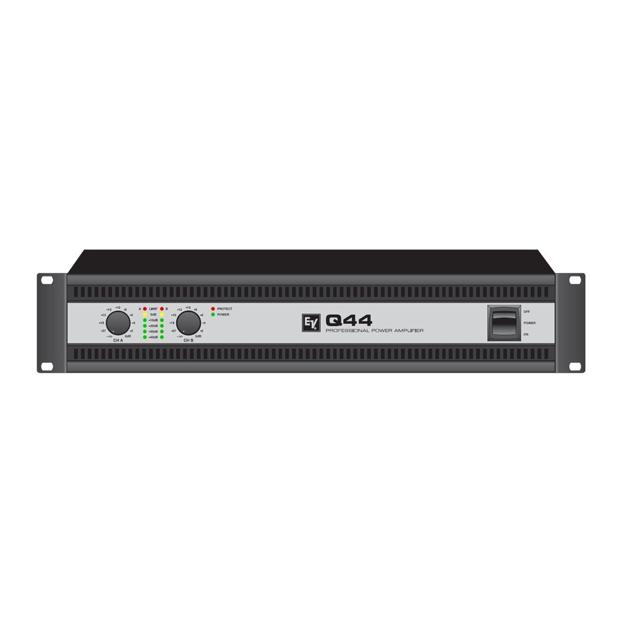
PROFESSIONAL POWER AMPLIFIER 2 Installation 2.1 Controls, Indicators and Connections Front View Input Level Control (CH A, CH B) for channels A and B Level Indicators for channels A and B Protections Indicator (PROTECT) Power On/Off Indicator (POWER) Mains Switch Rear View Mains Input Ground Lift Switch (CIRCUIT ⊥... -
Seite 8: Operating Voltage
2.5 Ventilation As with all Electro-Voice power amps with fan cooling, the airflow direction is front-to-rear, obviously because there is more cold air outside of the rack case than inside. The power amplifier remains cooler and dissipating the developing waste heat in a specific direction gets easier. -
Seite 9: Groundlift
PROFESSIONAL POWER AMPLIFIER 2.6 Groundlift The ground lift switch allows for eliminating noise loops. When operating the power amplifier together with other equipment in a rack case, setting the switch to the GROUNDED position is recommended. Set the switch to UNGROUNDED, when the power amplifier is operated together with appliances with differing ground potentials. -
Seite 10: Audio Input Cabeling
PROFESSIONAL POWER AMPLIFIER Speakon CHANNEL B Speakon CHANNEL A Connector Signal Table 2.1: Speaker connection using Speakon A and B connectors BRIDGED In BRIDGED mode both amp channels work in push-pull operation to provide doubled output voltage. The audio signal has to be applied to the input connectors of channel A, amplification is set via input level control of channel A only. - Seite 11 PROFESSIONAL POWER AMPLIFIER mandatory. Otherwise, a 6 dB drop in level could result. Please also see illustration 2.11. Due to their immunity against external interference sources, such as dimmers, mains connections, HF-control lines, etc., using balanced cabling and connections is always preferable. 2, HOT 3, COLD JUMPER...
-
Seite 12: Operation
PROFESSIONAL POWER AMPLIFIER 3 Operation 3.1 Volume Control In DUAL and PARALLEL mode, the level controls CH A and CH B on the power amp’s front panel are used to control the amplification of the corresponding channel. Turning the control to the right increases and turning it to the left decreases the volume. - Seite 13 PROFESSIONAL POWER AMPLIFIER Owner‘s Manual...
- Seite 14 PROFESSIONAL POWER AMPLIFIER INHALT Beschreibung ..............16 Willkommen .
- Seite 15 WICHTIGE SICHERHEITSHINWEISE Das Blitzsymbol innerhalb eines gleichseitigen Dreiecks soll den Anwender auf nicht isolierte Lei- tungen und Kontakte im Geräteinneren hinweisen, an denen hohe Spannungen anliegen, die im Fall einer Berührung zu lebensgefährlichen Strom- schlägen führen können. Das Ausrufezeichen innerhalb eines gleichseitigen Dreiecks soll den Anwender auf wichtige Bedie- nungs- sowie Servicehinweise in der zum Gerät gehörenden Literatur aufmerksam machen.
-
Seite 16: Beschreibung
PROFESSIONAL POWER AMPLIFIER 1 Beschreibung 1.1 Willkommen Vielen Dank, dass Sie sich für eine Endstufe der Electro-Voice Q Serie entschieden haben. Bitte lesen Sie diese Bedienungsanleitung aufmerksam durch, damit Sie Ihren neuen Electro-Voice Verstärker optimal nutzen können. 1.2 Auspacken und Inspektion Öffnen Sie die Verpackung und entnehmen Sie die Endstufe. -
Seite 17: Installation
PROFESSIONAL POWER AMPLIFIER 2 Installation 2.1 Bedienelemente, Anzeigen und Anschlüsse Frontseite Eingangspegel-Regler (CH A, CH B) für Kanal A bzw. B Pegelanzeige für Kanal A bzw. B Anzeige Schutzschaltung (PROTECT) Anzeige Betrieb (POWER) Netzschalter Rückseite Netzeingang Schalter Groundlift (CIRCUIT ⊥ TO CHASSIS SWITCH) Typenschild Audioeingangsbuchsen (INPUT A, INPUT B) Audioausgangsbuchsen (OUTPUT A, OUTPUT B) -
Seite 18: Betriebsspannung
Abbildung gezeigt. Geeignete Rackwinkel sind als Zubehör erhältlich. 2.5 Kühlung Bei allen lüftergekühlen Endstufen von Electro-Voice strömt die Luft von der Frontseite zur Rückseite, da kühle Frischluft eher außerhalb des Racks zur Verfügung steht als innerhalb. Die Endstufe bleibt kühler und die entstehende Abwärme kann gezielter abgeführt werden. -
Seite 19: Groundlift
PROFESSIONAL POWER AMPLIFIER ACHTUNG: Die Lüftungsöffnungen der Endstufe dürfen nicht blockiert/verschlossen werden. Bei fehlen- der Kühlung kann sich die Endstufe automatisch abschalten. Halten Sie alle Lüftungsöffnun- gen frei von Staubablagerungen, die den Luftstrom behindern würden. Betreiben Sie die Endstufe nicht in der Nähe von Wärmequellen wie Heizlüftern, Öfen oder an- deren Geräten, die Hitze abstrahlen. - Seite 20 PROFESSIONAL POWER AMPLIFIER Typische Lautsprecherverkabelung Die erste Möglichkeit für den Anschluss von Lautsprechern in den Betriebsarten DUAL und PARALLEL ist die Verwendung beider Speakon- Buchsen, wobei in jeder der Buchsen der Lautsprecher jeweils an den Anschlüssen 1+ und 1- angeschlossen wird, siehe nebenstehende Abbildung.
-
Seite 21: Verkabelung Des Audio-Eingangs
PROFESSIONAL POWER AMPLIFIER ACHTUNG: Im Brückenbetrieb darf die angeschlossene Last 4 Ω nicht unterschreiten. Es können sehr hohe Spannungen am Ausgang produziert werden. Die angeschlossenen Lautsprecher müs- sen für derart hohe Spannungen ausgelegt sein. Beachten Sie unbedingt die Leistungsanga- ben im Datenblatt des jeweiligen Lautsprechers und vergleichen Sie diese mit der entsprechenden Ausgangsleistung der Endstufe. -
Seite 22: Betrieb
PROFESSIONAL POWER AMPLIFIER 3 Betrieb 3.1 Eingangspegel-Regler In den Betriebsarten DUAL und PARALLEL regeln die Eingangspegel-Regler CH A und CH B an der Frontseite der Endstufe die Verstärkung des jeweiligen Kanals. Drehung nach rechts erhöht die Lautstärke, Drehung nach links verringert die Lautstärke. Im Brückenbetrieb (BRIDGED) regelt nur der Drehknopf von Kanal A (CH A) die Lautstärke, die Drehknopf-Einstellung von Kanal B (CH B) wird ignoriert. -
Seite 23: Specifications/Technische Daten
PROFESSIONAL POWER AMPLIFIER Specifications/Technische Daten Amplifier at rated conditions, both channels driven, 8 Ω load, unless otherwise specified. Q1212 2 Ω 4 Ω 8 Ω 2 Ω 4 Ω 8 Ω 2 Ω 4 Ω 8 Ω 2 Ω 4 Ω 8 Ω... -
Seite 24: Block Diagram / Blockschaltbild
PROFESSIONAL POWER AMPLIFIER Block Diagram / Blockschaltbild Owner‘s Manual / Bedienungsanleitung... - Seite 25 PROFESSIONAL POWER AMPLIFIER Dimensions / Abmessungen Owner‘s Manual / Bedienungsanleitung...
- Seite 26 PROFESSIONAL POWER AMPLIFIER Owner‘s Manual / Bedienungsanleitung...
- Seite 27 PROFESSIONAL POWER AMPLIFIER Owner‘s Manual / Bedienungsanleitung...
- Seite 28 Americas Asia & Pacific Rim Bosch Communications Systems Japan: EVI Audio Japan Ltd. 12000 Portland Ave South 5-3-8 Funabashi, Setagaya-Ku Burnsville, MN 55337, USA Tokyo, Japan 156-0055 USA: Phone:1-800-392-3497 Phone: +81 3-5316-5020 Fax: 1-800-955-6831 Fax: +81 3-5316-5031 Canada: Phone: 1-866-505-5551 China: Bosch Communications Systems Fax:1-866-336-8467...