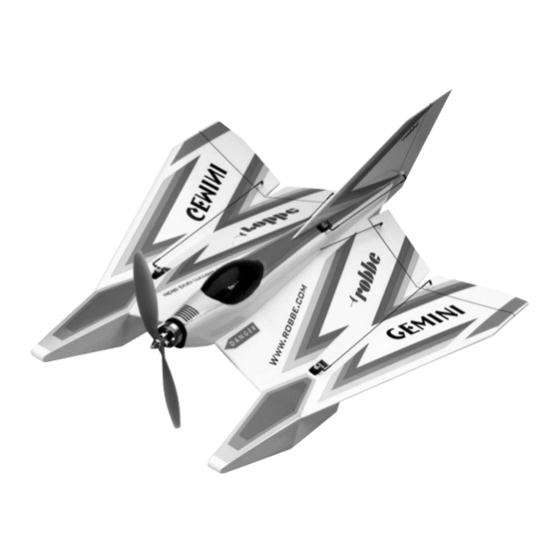
Inhaltszusammenfassung für ROBBE 3123
- Seite 1 Bau- und Betriebsanleitung Assembly and Operating instructions Notice de montage et d´utilisation Gemini No. 3123...
- Seite 2 Werkzeuge und Hilfsmittel siehe robbe Hauptkatalog See the main robbe catalogue for details of tools and aids to building. Outillage et accessoires de montage, cf. catalogue général robbe...
- Seite 3 Bauanleitung, Assembly instructions, Notice de montage Gemini 3123 Sender Mittelstellung). Eventuell montierte trims central). Remove the servo output arms or discs. schéma d'implantation. À vous d'ajuster les différences Steuerscheiben oder Servohebel entfernen. When switching on the system always keep to this de cotes.
- Seite 4 Bauanleitung, Assembly instructions, Notice de montage Gemini 3123...
- Seite 5 Bauanleitung, Assembly instructions, Notice de montage Gemini 3123 Bild 1 Fig. 1 Fig. 1 - Die tiefgezogenen Kufen-Abdeckungen gemäß - Trim the vacuum-moulded skid covers by cutting them - Couper les carénages des patins d’atterrissages en Markierungen beschneiden. along the marked lines.
- Seite 6 Bauanleitung, Assembly instructions, Notice de montage Gemini 3123...
- Seite 7 Bauanleitung, Assembly instructions, Notice de montage Gemini 3123 Bild 5 Fig. 5 Fig. 5 - Das Höhenruderservo in Neutralstellung bringen, - Set the elevator servo to the neutral position and fit the - Amener le servo de profondeur au neutre et monter le Servohebel montieren.
- Seite 8 Bauanleitung, Assembly instructions, Notice de montage Gemini 3123...
- Seite 9 Bauanleitung, Assembly instructions, Notice de montage Gemini 3123 Bilder 9 und 10 Figs. 9 and 10 Fig. 9 et 10 - Die Höhenruder in Neutralstellung bringen und fixieren. - Temporarily fix the elevators at the neutral position. - Amener le le servo de profondeur au neutre et le fixer.
- Seite 10 Bauanleitung, Assembly instructions, Notice de montage Gemini 3123 90°...
- Seite 11 Bauanleitung, Assembly instructions, Notice de montage Gemini 3123 Bild 13 Fig. 13 Fig. 13 - Seitenleitwerk und Ruder gemäß Detailzeichnung an - Bevel the trailing edge of the fin and the leading edge of - Biseauter la dérive et la gouverne au niveau des arêtes den Kanten anschrägen.
- Seite 12 Bauanleitung, Assembly instructions, Notice de montage Gemini 3123...
- Seite 13 Bauanleitung, Assembly instructions, Notice de montage Gemini 3123 Bild 17 Fig. 17 Fig. 17 - Länge des Seitenrudergestänges: ca. 230 mm - Set the rudder pushrod to a length of around 230 mm. - Longueur de la timonerie de direction : approximative- ment 230 mm.
- Seite 14 Bauanleitung, Assembly instructions, Notice de montage Gemini 3123...
- Seite 15 Bauanleitung, Assembly instructions, Notice de montage Gemini 3123 Bild 21 Fig. 21 Fig. 21 - Kabel nach innen führen und am V-Kabel anschließen. - Run the aileron servo cables into the fuselage and - Agencer les cordons vers l’intérieur et les raccorder au connect them to the Y-lead as shown.
- Seite 16 Bauanleitung, Assembly instructions, Notice de montage Gemini 3123...
- Seite 17 Bauanleitung, Assembly instructions, Notice de montage Gemini 3123 Bild 25 Fig. 25 Fig. 25 - Den Motor mit den beigefügten Senkschrauben am - Attach the motor to the motor mount using the coun- - Fixer le moteur au couple-moteur à l’aide des vis à tête Motorspant befestigen.
- Seite 18 Bauanleitung, Assembly instructions, Notice de montage Gemini 3123 “W” “W” C.G.
- Seite 19 Bauanleitung, Assembly instructions, Notice de montage Gemini 3123 Figs. 29 and 30 Fig. 29 et 30 Bilder 29 und 30 - Connect the speed controller to the motor and attach it - Raccorder le variateur au moteur et les fixer dans le - Regler am Motor anschließen und mit Klettband...
- Seite 20 Bauanleitung, Assembly instructions, Notice de montage Gemini 3123 Querruder, aileron, aileron 20 mm 20 mm Seitenruder, rudder, direction 30 mm 30 mm Höhenruder, elevator, profondeur 15 mm 15 mm...
- Seite 21 Bauanleitung, Assembly instructions, Notice de montage Gemini 3123 Funktionsprobe, Bilder 33 und 34 Checking the working systems, fig. 33 and 34 Essai des fonctions, fig 33 et 34 - Knüppel und Trimmungen am Sender in Mittelstellung - Ensure that the transmitter sticks and trims are central.
- Seite 22 Bauanleitung, Assembly instructions, Notice de montage Gemini 3123 - Die Laufrichtung des Motors prüfen. Der Motor muß, - Attention : disposer le manche des gaz selon les indi- von vorn gesehen, gegen den Uhrzeigersinn drehen. - Check the direction of rotation of the motor: when cations de la notice du variateur de sorte que le moteur Sollte dies nicht der Fall sein, (z.
- Seite 23 à son point de départ the model back to the starting point. avec suffisamment d’énergie résiduelle. robbe Modellsport GmbH & Co. KG - After the flight, check that no water has managed to - Après l’atterrissage, vérifier l’absence d’eau dans l’in- penetrate inside the model.
- Seite 24 Sous réserve de d’erreur et de modification technique. Copyright robbe-Modellsport 2006 Copie et reproduction, même d’extraits, interdites sans autorisation écrite expresse de la Société robbe-Modellsport GmbH & Co. KG robbe Modellsport GmbH & Co. KG Metzloserstr. 36 Telefon: 06644 / 87-0...


