Sharp XG-P25X Service Anleitung
Inhaltsverzeichnis
Verfügbare Sprachen
Verfügbare Sprachen
Quicklinks
In the interests of user-safety (Required by safety regulations in some countries) the set should be restored
to its original condition and only parts identical to those specified should be used.
Im lnteresse der Benutzersicherheit (erforderliche Sicherheitsregeln in einigen Ländern) muß das Gerät in seinen
Originalzustand gebracht werden. Außerdem dürfen für die spezifizierten Bauteile nur identische Teile verwendet
werden.
SHARP CORPORATION
SERVICE MANUAL
SERVICE-ANLEITUNG
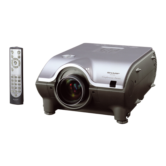
LCD PROJECTOR
LCD PROJEKTOR
MODEL
MODELL
This document has been published to be used for
after sales service only.
The contents are subject to change without notice.
XG-P25X
XG-P25X
S62L5XG-P25X/
Inhaltsverzeichnis

Verwandte Anleitungen für Sharp XG-P25X


Inhaltszusammenfassung für Sharp XG-P25X
-
Seite 58: Technische Daten
Bilder abhängig vom Signaltyp nicht wie vorgesehen wiedergegeben werden. In diesem Fall sollte der Komponenten-Eingang, Video-Eingang oder S-Video-Eingang verwendet werden. Dieser Projektor von SHARP ist mit 3 LCD- (Flüssigkristallanzeige) Dieses Gerät hat einige inaktive, innerhalb akzeptierter Projektionspaneels ausgestattet. -
Seite 59: Hinweise Für Das Wartungspersonal
XG-P25X HINWEIS FÜR DAS WARTUNGSPERSONAL 1 2 3 4 5 6 7 8 9 0 1 2 3 4 5 6 7 8 9 0 1 2 3 4 5 6 7 8 9 0 1 2 1 2 3 4 5 6 7 8 9 0 1 2 3 4 5 1 2 3 4 5 6 7 8 9 0 1 2 3 4 5 6 7 8 9 0 1 2 3 4 5 6 7 8 9 0 1 2 1 2 3 4 5 6 7 8 9 0 1 2 3 4 5 Ë... -
Seite 60: Lage Der Bedienelemente
XG-P25X Lage der Bedienelemente Projektor Vorderansicht Lampe Austausch-Anzeige Temperaturwarnanzeige Betriebsanzeige Netz-Tasten (ON/OFF) Lautstärke-Tasten – + (VOLUME / ) Stummschaltungs-Taste (MUTE) Menü-Taste (MENU) Objektiv-Taste (LENS) Auto-Synchron-Taste (AUTO SYNC) Eingangs-Tasten 1, 2, 3, 4, 5 (INPUT) Größe-Taste (RESIZE) Standbild-Taste (FREEZE) GAMMA-Taste Schwarzbild-Taste (BLACK SCREEN) -
Seite 61: Betrieb Mit Der Drahtlosen Maus-Fernbedienung
XG-P25X Betrieb mit der drahtlosen Maus-Fernbedienung Fernbedienung Vorderansicht Netz-Tasten (ON/OFF) Objektiv-Taste (LENS) Menü-Taste (MENU) Eingabe-Taste (ENTER) Einstellungs-Tasten ( / / / ) Storno-Taste (UNDO) Vergrößern-Tasten (ENLARGE) Standbild-Taste (FREEZE) Auto-Synchron-Taste (AUTO SYNC) GAMMA-Taste Schwarzbild-Taste (BLACK SCREEN) Eingangs-Taste 3 (INPUT 3) Eingangs-Taste 1 (INPUT 1) Eingangs-Taste 2 (INPUT 2) Größe-Taste (RESIZE) -
Seite 62: Pin-Belegung
XG-P25X Pin-Belegung INPUT 1 RGB- und OUTPUT (INPUT 1, 2)-Signalanschlüsse: 15-Pin Mini-D-Sub-Buchse RGB-Eingang Analog 1. Videoeingang (rot) 8. Erdung (blau) 2. Videoeingang 9. Nicht angeschlossen (Grün/Sync. auf Grün) 10. MASSE 3. Videoeingang (blau) 11. MASSE 4. Reserveeingang 1 12. Bi-direktionale Daten 5. -
Seite 63: Abmessungen
XG-P25X Abmessungen Ansicht der Rückseite Seitenansicht Ansicht von oben Seitenansicht (155) (26,5) (319) (3,5) (23) Ansicht von vorne (34) (248) (88,5) 2 (74,5) Ansicht von unten Einheit: Zoll (mm) (20,27) -
Seite 64: Entfernen Der Hauptteile
XG-P25X ENTFERNEN DER HAUPTTEILE 1. Entfernen des oberen Gerätedeckels und des Objektiv-Abdeckungsrings 1-1. Die beiden Schrauben losdrehen und den Objektiv-Abdeckungsring abnehmen. 1-2. Den oberen Gerätedeckel festhalten und nach oben kippen, bis das hintere Ende in geneigter Stellung stehenbleibt. Danach den Gerätedeckel abschieben und entfernen. Nun den Objektivverschluß abnehmen. -
Seite 65: Entfernen Der Luftansaugabdeckung Und Der Lampeneinheit
XG-P25X 2. Entfernen der Luftansaugabdeckung und der Lampeneinheit 2-1. Die Luftansaugabdeckung abnehmen. 2-2. Die Schraube losdrehen und die Lampenabdeckung abschieben. 2-3. Die drei Schrauben losdrehen und die Lampe herausnehmen. 3. Entfernen des hinteren Gehäuseteils 3-1. Die sechs Schrauben vom Anschlußgbrett am hinteren Gehäuseteil losdrehen. - Seite 66 XG-P25X 4. Entfernen des oberen Gerätedeckels 4-1. Die fünf Schrauben losdrehen. 4-2. Die vier Schrauben losdrehen. 4-3. An beiden Seiten des Gerätes hineindrücken und die Haken lösen. Den oberen Gerätedeckel mit dem Objektivschalthebel hochheben und die beiden Stecker abziehen. Objektivschalthebel...
-
Seite 67: Entfernen Der Platineneinheit
XG-P25X 5. Entfernen der Platineneinheit 5-1. Die oberen Haken lösen und die GYRO-Platine entfernen. 5-2. Die Anschlußstecker von der GYRO-Platine abziehen. 5-3. Die fünf Schrauben losdrehen und die PC-Schnittstelleneinheit abnehmen. 5-4. Die fünf Stecker abziehen. 5-5. Die beiden Schrauben losdrehen und die Ausgangs-Hilfsplatine entfernen. -
Seite 68: Vorsichtsmaßnahmen Beim Einbau
XG-P25X Vorsichtsmaßnahmen beim Einbau 5-9. Das Teil a der Eingangsplatine in den Schlitz der unteren Abdeckung einstecken. 5-10. Die Abschirmung der Eingangsplatine mit der Oberseite der Netzeingangsabschirmung b ausrichten. 5-11. Vor dem Festziehen der Schrauben (5-7) sowie der Schrauben und Sechskantmuttern (5-8) ist die Platineneinheit ausreichend nach vorne zu schieben c . -
Seite 69: Entfernen Der Netz/Ballast/Tonausgang/Bimetalleinheit
XG-P25X 6. Entfernen der Netz/Ballast/Tonausgang/Bimetalleinheit 6-1. Die Schraube losdrehen, dann das Erdungskabel vom Abschirmgehäuse der Netz/Ballast-Einheit abziehen. 6-2. Die Stecker von der Tonausgangsplatine abziehen. 6-3. Die Bimetall-Steckdose herausnehmen. 6-4. Die beiden Schrauben losdrehen, dann die Lampenfassung entfernen. 6-5. Die drei Schrauben losdrehen, dann das Netzteil entfernen. -
Seite 70: Entfernen Der Optik-Mechanismuseinheit
XG-P25X 7. Entfernen der Optik-Mechanismuseinheit 7-1. Die beiden Schrauben vom Ansauggebläse der Optik-Mechanismuseinheit losdrehen. 7-2. Die acht Schrauben losdrehen, dann die Optik-Mechanismuseinheit herausnehmen. 7-3. Die Schraube losdrehen und das Erdungskabel anschließen. 7-4. Den Stecker abziehen und die Netzeingangseinheit herausnehmen. Optik-Mechanismuseinheit... -
Seite 71: Rückstellen Des Lampenbetriebszeit-Timers
Ort aufstellen. anzeige im Gerät ist zu hoch. • Luftfilter verstopft. • Den Filter reinigen. • Kühlventilator beschädigt. • Den Projektor zu einem von Sharp • Interne Schaltkreise autorisierten Händler für LCD-Projektoren beschädigt. oder dem Kundendienst zur Reparatur geben. Die Lampe •... -
Seite 72: Übersicht Der Optikeinheit
XG-P25X ÜBERSICHT DER OPTIKEINHEIT Übersicht des optischen Systems Hinweis: Anordnung der Bauteile im optischen System Projektionsobjektiv 1/2λ-Platte 1/2λ-Platte + Polarisationsplatte Saphirglas Saphirglas Polarisationsplatte Polarisationsplatte Polarisatorplatte B für einfallendes Licht Polarisatorplatte R für einfallendes Licht Zweifarbige Beschichtung Zweifarbige Beschichtung (R-Übertragung) (B-Übertragung) -
Seite 73: Einstellung Von Konvergenz Und Brennpunkt
XG-P25X EINSTELLUNG VON KONVERGENZ UND BRENNPUNKT » Bei eingeschaltetem Gerät, entferntem oberen Gehäuseteil und abgenommenen LCD- Abdeckungen mit den Konvergenz- und Brennpunkteinstellungen beginnen. Das Bild wird mit der Fernbedienung eingestellt. Es sind die folgenden Bedienschritte auszuführen: 1. Fokussieren des Projektionsobjektivs (A) Auswechseln aller 3 Flüssigkristallanzeigen (LCD) -
Seite 74: Konvergenz- Und Brennpunkt-Einstellmechanismus
XG-P25X (B) Konvergenzeinstellung » Für diese Einstellung ist ein Kreuzschraffier-Muster zu benutzen. Die Einstellung ist ausschließlich für die G-Farbe und die zutreffende Farbe. (1) Die Konvergenz-Sicherungsschraube “d” lockern. (2) Die Konvergenz-Sicherungsschraube “d” lockern. (3) Schließlich die Konvergenz-Sicherungsschraube “d” festziehen. Hinweis: 1 Der exzentrische Nocken wird für die Einstellung der Konvergenz benutzt. -
Seite 75: Konvergenz- Und Brennpunkteinstellungen Auf Einen Blick Einstellrichtungen
XG-P25X Konvergenz- und Brennpunkteinstellungen auf einen Blick Einstellrichtungen Einstellung Richtung Definition Richtung der LCD-Anzeige X-Richtung LCD rechts und links Konvergenz Y-Richtung LCD oben und unten θZ-Richtung Drehung um die Z-Achse LCD-Drehachse Z-Richtung LCD, optische Achse θX-Richtung Drehung um die X-Achse... -
Seite 76: Auswechseln Der G-Lcd- Und B-Lcd-Tafeln
XG-P25X Auswechseln der G-LCD- und B-LCD-Tafeln Bei entferntem oberen Gehäuseteil (1) Das LCD-Flachkabel vom Stecker der Ausgangsplatine abziehen. (2) Die Schrauben “b” und “c” losdrehen. Die R/B-Einstellscheibe oder die G-Einstellscheibe zusammen mit der LCD-Tafel abnehmen. (3) Die LCD-Tafel von der Einstellscheibe trennen. -
Seite 77: Auswechseln Der R-Lcd-Tafel
XG-P25X Auswechseln der R-LCD-Tafel (1) Das LCD-Flachkabel vom Ausgangsplatinenstecker abziehen. <Abbildung 1> (2) Die beiden Schrauben "A" losdrehen. (3) Die Platte "B" zusammen mit der Einfallslicht-Abdeckplatte anheben und entfernen. <Abbildung 2> (4) Die vier Schrauben "C" losdrehen, dann die Einheiten "D" und "E" voneinander trennen. -
Seite 78: Einstellung Der Optischen Achse Der Spiegel (M1, M5 Und M6)
XG-P25X Einstellung der optischen Achse der Spiegel (M1, M5 und M6) Die optische Achse muß nachjustiert werden, wenn mit den R-, G- oder B-Spiegeln eine Verdunkelung auftritt. Im allgemeinen wird diese Einstellung erforderlich, wenn irgendeine zur Optik zählende Komponente ausgewechselt wird. - Seite 79 XG-P25X Einstellen des Glühlampenschachts. Sicherungsschrauben Glühlampenschacht Diese Einstellung ist erforderlich, nachdem die Glühlampe ersetzt wurde und eine ungleichmäßige Abbildung erhalten wird (rechte und linke Seite am Bildschirm weisen eine Ungleichmäßigkeit auf). (1) Die Glühlampe einschalten. (2) Ein Signal für das weiße Testmuster mit 100% zuführen.
-
Seite 80: Elektrische Einstellung
XG-P25X ELEKTRISCHE EINSTELLUNG Einen Signalgenerator, PC oder Macintosh-Computer am Projektor anschließen, um die in den Einstellbedingungen spezifizierten Signale zuzuführen. Einstellposition Einstellbedingung Einstellverfahren » Folgende Einstellungen vornehmen: EEPROM- 1. Den Netzschalter Initialisierung S2601 drücken, um den Verarbeitungsmodus einschalten und das Gerät für ca. - Seite 81 XG-P25X Einstellposition Einstellbedingung Einstellverfahren » Die PSIG-Wellenform so einstellen, daß sie der P-SIGNAL 1. Das Oszilloskop an untenstehenden Abbildung entspricht. TP1102 für Rot anschließen. 2. Die folgende Wahl treffen. Gruppe : OUTPUT 2 PSIG Gegenstand : PSIG-H PSIG-L 2,5VGleichspannung 5,0V Gleichspannung (Mit PSIG-H einstellen.)
- Seite 82 XG-P25X Einstellposition Einstellbedingung Einstellverfahren » Die Daten für R1-BLK und B1-BLK für den RGB- 1. Das Grauskalensignal (32 Weißbalance Abstufungen) zuführen Schwarzabgleich an der Grauskala einstellen. (XGA 60Hz). Danach die Daten für R1-GAIN und B1-GAIN für Gruppe : OUTPUT 1 den Mitte-/Weißabgleich an der Grauskala...
- Seite 83 XG-P25X Einstellposition Einstellbedingung Einstellverfahren » Die Differenz (100%) des Weiß- und Rotanteils auf NTSC- 1. Das Trennfarbbalkensignal Farbsättigungspegel zuführen. 0,30 ±0,02 Vs-s einstellen. Hierfür die Gruppe : VIDEO 1 Regelschalter oder die Tasten auf der Gegenstand : N-COLOR Fernbedienung betätigen.
- Seite 84 XG-P25X Einstellposition Einstellbedingung Einstellverfahren » Die Regelschalter oder die Fernbedienungstasten DVD-Kontrast 1. Das Farbbalken-Signal des Komponentensignals 480I verwenden und Einstellung vornehmen, bis das an der Eingangsklemme Weißsignal (100%) bitlos erscheint. » Schießlich die Kontrast-Einstellung um 2 Punkte BNC G(Y) zuführen.
- Seite 85 XG-P25X Einstellposition Einstellbedingung Einstellverfahren » Im Verarbeitungsmodus L1 anwählen. Die Farbe Leistungsprüfung 1. Das Farbbalkensignal des Farbsystems empfangen. und die Tönung überprüfen. » Im Verarbeitungsmodus L2 anwählen. Die Farbe Leistungsprüfung 1. Das Monoskopsignal des Videosystems empfangen. und die Tönung überprüfen.
-
Seite 86: Einstellen Und Überprüfen Des Pegels
XG-P25X EINSTELLUNG DER PC-SCHNITTSTELLE (CPCi-0054CE01/02. PC I/F Einheit) 1. Initialisierung des Geräts. 1) Den S2601-Schalter drücken, um den Prozeßmodus zu aktivieren. 2) S1 des SSS-Menüs durchführen. (Mit S1 wird nur die PC I/F-Platine initialisiert. S2 darf nicht durchgeführt werden, da hierdurch die Einstelldaten mit Ausnahme der PC-Platine initialisiert werden. -
Seite 87: Einstellungsmenüliste
XG-P25X EINSTELLUNGSMENÜLISTE P25X( OUTPUT1 OUTPUT2 OUTPUT3 VIDEO1 VIDEO2 NOKO LINE PATTERN CVIC LENS SPECIAL Jede Menüliste OUTPUT1 OUTPUT2 R-BRIGHT R1-BLK PSIG-H G-BRIGHT R1-GAIN PSIG-L B-BRIGHT G1-BLK R2-BLK G1-GAIN G2-BLK B1-BLK B2-BLK B1-GAIN OUTPUT3 VIDEO G-BRIGHT NTSC-H CB-OFFSET PICTURE CR-OFFSET BRIGHT... -
Seite 88: Fehlersuchtabelle
XG-P25X FEHLERSUCHTABELLE Überprüfung der Platinenleistung Gestörter Durchgangs- Gestörter Videoeingang. Gestörte RGB-Eingabe. Fernbedienungskabel defekt. Ausgang. Zum Abschnitt "Überprüfung Zum Abschnitt "Prüfung des Ein Mustersignal vom PC Gestörter Durchgangs- des Fernbedienungs- Videoschaltkreises" zuführen. Ausgangsschaltkreis. Schaltkreises" weitergehen. weitergehen. Wurde zwischen PC und Nein... -
Seite 89: Überprüfung Des Videosystems
XG-P25X FEHLERSUCHTABELLE (Fortsetzung) Überprüfung des Videosystems Nein Leuchtet die Lampe? Zum Abschnitt “Lampe leuchtet nicht auf” weitergehen. Nein Wird die vorgeschriebene Spannung den EA-Anschlüssen zugeführt? Den Netzschaltkreis und seine zugehörigen Bauteile überprüfen. Nein Liegen Eingangssignale an den Stiften (9), (19) und (21) von SC401 an? -
Seite 90: Überprüfung Des Rgb-Ausgangssignalkreises
XG-P25X FEHLERSUCHTABELLE (Fortsetzung) Überprüfung des RGB-Ausgangssignalkreises Nein Liegen an den Stiften (1), (3) und (5) von IC4301 RGB Eingang- Wellenformen an? IC3302 der Eingangseinheit und seine Peripherieschaltkreise überprüfen. Liegen an den Stiften (16), (18) und Nein (20) von IC4301 Ausgangsellenformen an? Den IC4301-Wahlschalter, die Anschlußspannung und die... - Seite 91 XG-P25X FEHLERSUCHTABELLE (Fortsetzung) Kein oder ungewöhnliches Y-Signal Nein Liegen Y-Eingangssignale am Stift (84) von IC4502 an? IC4502 und seine Peripherieschaltkreise überprüfen. Nein Liegen Y-Ausgangssignale am Stift (7) von IC4501 an? IC4501 und seine peripheren Schaltkreise überprüfen. Nein Liegen Y-Ausgangssignale am Stift...
-
Seite 92: Überprüfung Der Ausgangsplatine
XG-P25X FEHLERSUCHTABELLE (Fortsetzung) Überprüfung der Ausgangsplatine Liegen Eingangssignale an Nein Nein SC8405, SC8502 und SC8404 an? Wird den EA-Steckern Spannung zugeführt? Wenn keine Signale am EA- Falls an P4302, P4303 und Steckverbinder oder SC8404, P4301 kein Signal anliegt, Zum SC8405 und SC8502 anliegen, Abschnitt "Überprüfung des... -
Seite 93: Überprüfung Des Netzgeräts
XG-P25X FEHLERSUCHTABELLE (Fortsetzung) Kein Ton Liegen Audio-Ausgangssignale an Nein den Stiften (2) und (23) von IC331 Den Eingangsschaltkreis, den Umschalt-Schaltkreis von IC461 bis IC464 und ihre Peripherieschaltkreise überprüfen. Nein Liegen Audio-Ausgangssignale an den Stiften (1) und (2) von P301 an? -
Seite 94: Gerät Eingeschaltet
XG-P25X FEHLERSUCHTABELLE (Fortsetzung) Gerät eingeschaltet Nein Wurde der korrekte Eingang gewählt? Den korrekten Eingang mit der Fernbedienung anwählen Entsprechen die PC-, Video- und Nein LCP-Kabel den Spezifikationen und sind diese richtig angeschlossen? Die korrekten Kabel benutzen oder erneut anschließen Erscheint das Bild bei maximaler... -
Seite 95: Die Lampe Leuchtet Nicht
XG-P25X FEHLERSUCHTABELLE (Fortsetzung) Die Lampe leuchtet nicht Den Netzschalter einschalten. Wird in der Lampe ein Entladegeräusch erzeugt? Nein Sitzt die Lampe nicht in ihrer Fassung? Nein Nein Läuft das Ballast-Kühlgebläse? Die Lampe wieder in die Die Lampe Fassung ersetzen. Den Netzschaltkreis einsetzen. -
Seite 96: Fehlersuchtabelle Für Pc I/F Einheit
XG-P25X FEHLERSUCHTABELLE für PC I/F EINHEIT Überprüfung der PC- Platine Wird das Benutzermenü am Bildschirm angezeigt? Nein Die Bildschirmanzeige überprüfen. Den Grund-Signalfluß überprüfen. Die Komponent-Signale und Video-Signale fließen in gleicher Richtung von CVIC IC Den RGB-Eingang zu DAC OUT. Es besteht daher kein überprüfen. -
Seite 97: Die Autosync-Funktion
XG-P25X FEHLERSUCHTABELLE für PC I/F EINHEIT (Fortsetzung) Überprüfung des RGB- Eingangs Die durch den Synchronimpuls getrennten RGB-Signale dem Anschluß INPUT1 oder INPUT2 zuleiten. INPUT1 oder INPUT2 mit der Taste auf der Schalttafel oder der Fernbedienung anwählen. Nein Erscheint das Bild? Die Video-Eingangssignale überprüfen. - Seite 98 XG-P25X FEHLERSUCHTABELLE für PC I/F EINHEIT (Fortsetzung) Überprüfung des Videoeingangs Die Eingangssignal- Einstellungen überprüfen. Liegt an der Anschlußfläche Nein von C8007 ein Videosignal IEingangsplatine defekt. Die Synchronsignale überprüfen. IC8025 oder IC8004 defekt. Überprüfung der Eingangssignal-Einstellungen. Entspricht das angewählte Nein Eingangsmenü der...
- Seite 99 XG-P25X FEHLERSUCHTABELLE für PC I/F EINHEIT (Fortsetzung) Überprüfung der Synchronsignale Nein Liegt am TL8134 ein Vertikal-Synchronsignal an? Nein Liegt am TL8133 ein Horizontal-Synchronsignal an? Die Eingangssignal- Einstellungen überprüfen. Eingangsplatine defekt. Nein Liegt am TL8131 ein Vertikal-Synchronsignal an? Liegt am TL8130 ein...
- Seite 100 XG-P25X FEHLERSUCHTABELLE für PC I/F EINHEIT (Fortsetzung) Überprüfung der RGB- Signale Nein Ist der Signaltyp RGB angewählt? Die RGB-Signaleinstellungen Den Prozeßmodus abrufen. R, G und B einzeln aus dem Mustermenü abrufen. Zum Schritt "Überprüfung von GA4 und seiner peripheren Bauteile" weitergehen.
- Seite 101 XG-P25X FEHLERSUCHTABELLE für PC I/F EINHEIT (Fortsetzung) Überprüfung von GA4 und seiner peripheren Bauteile R, G und B einzeln aus dem Prozeß-Mustermenü abrufen. Entsprechen die R-, G- und B-Farben den spezifizierten Werten? Nein GA4-Überprüfung abgeschlossen. Die Signale FB8004, FB8005 und FB8006 auf dem Oszilloskop-Bildschirm messen.
- Seite 102 XG-P25X FEHLERSUCHTABELLE für PC I/F EINHEIT (Fortsetzung) Überprüfung des Komponenteneingangs (4801 nicht eingeschlossen) Die Komponent-Signale dem Anschluß INPUT1 oder INPUT2 zuleiten. INPUT1 oder INPUT2 mit der Taste auf der Schalttafel oder der Fernbedienung anwählen. Nein Erscheint das Bild? Zum Schritt "Überprüfung des SOG-Schaltkreises"...
- Seite 103 XG-P25X FEHLERSUCHTABELLE für PC I/F EINHEIT (Fortsetzung) Überprüfung des SOG- Schaltkreises Das Signal am TP8136 am Oszilloskop-Bildschirm messen. Werden die Synchron- Kanalsignale in der spezifizierten Zeitspanne reproduziert? Nein Der SOG-Schaltkreis ist in Ordnung. Ende. Die Anschlußfläche von C8069 auf dem Oszilloskop- Bildschirm messen.
- Seite 104 XG-P25X FEHLERSUCHTABELLE für PC I/F EINHEIT (Fortsetzung) Überprüfung des Videoeingangs Das Videokanalsignal dem Anschluß INPUT4 zuführen. INPUT4 mit der Taste auf der Schalttafel oder der Fernbedienung anwählen. VIDEO als Signaltyp am Benutzermenü anwählen. Nein Verschwindet das Bild? Zum Schritt "Überprüfung des Video- Synchronsignals"...
- Seite 105 XG-P25X FEHLERSUCHTABELLE für PC I/F EINHEIT (Fortsetzung) Das VPC-Taktsignal (IC8338) am TL8004 messen. Nein Ist das Taktsignal wie spezifiziert? IC8338 defekt. Zum Schritt "Überprüfung des Video-Synchronsignals" weitergehen. IC8025 oder seine peripheren Bauteile defekt. Überprüfung des Video- Synchronsignals Das Signal am TL8140 auf dem Oszilloskop-Bildschirm messen.
- Seite 106 XG-P25X FEHLERSUCHTABELLE für PC I/F EINHEIT (Fortsetzung) Liegen die Horizontal- und Nein Vertikal-Synchronsignale am TL8130 und TL8131 an? IC8302 oder seine peripheren Bauteile defekt. Liegt am FL8004 das Nein spezifizierte Taktsignal an? IC8338 oder seine peripheren Bauteile defekt. Ende...
- Seite 107 XG-P25X FEHLERSUCHTABELLE für PC I/F EINHEIT (Fortsetzung) Hinweis: Um das Funktionieren des Plug&Play- Überprüfung des DVI-Digitaleingangs Systems zu sicherzustellen, das Kabel zuerst am INPUT3-Anschluß anschließen und danach erst den Computer (Signalgenerator) einschalten. Das DVI-Digitalsignal dem INPUT3-Anschluß zuführen. INPUT3 für den Eingangsanschluß...
- Seite 108 XG-P25X FEHLERSUCHTABELLE für PC I/F EINHEIT (Fortsetzung) Überprüfung des DVI- Analogeingangs Das DVI-Digitalsignal dem INPUT3- Anschluß zuführen. INPUT3 für den Eingangsanschluß anwählen. Nein Erscheint das Bild? Überprüfen, ob die R-, G- und B- Signale an den Stiften (126), (136) Bestehen Bildstörungen? und (141) des IC8004 anliegen.
- Seite 109 XG-P25X FEHLERSUCHTABELLE für PC I/F EINHEIT (Fortsetzung) Sie DVI-Analogsignale sind durch den CXA3516R SOG- Überprüfung des DVI SOG- getrennt. Das Grün-Signal wird dem SOGIN2-Anschluß Schaltkreises zugeführt. Das DVI SOG-Synchronsignal wird mit dem Bus-Schalter (IC23) angewählt. Liegt das Horizontal- Synchronsignal am TL8082 an?
-
Seite 110: Chassis Layout
XG-P25X CHASSIS LAYOUT / CHASSIS-ANORDNUNG... - Seite 111 XG-P25X...
-
Seite 112: Blockschaltbild
XG-P25X BLOCK DIAGRAM / BLOCKSCHALTBILD... - Seite 113 XG-P25X...
-
Seite 114: Overall Wiring Diagram
XG-P25X OVERALL WIRING DIAGRAM / GESAMTSCHALTPLAN... - Seite 115 XG-P25X...
-
Seite 116: Description Of Schematic Diagram
XG-P25X DESCRIPTION OF BESCHREIBUNG DES SCHEMATIC DIAGRAM SCHEMATISCHEN SCHALTPLANS VOLTAGE MEASUREMENT CONDITION: SPANNUNGSMESSUNGEN: 1. Voltages at test points are measured at the 1. Spannungen an den Prüfpunkten werden bei einer Netzspannung von 220V gemessen, Signale werden supply voltage of AC 220V. Signals are fed by a für die Wartung mit einem Farbbalken-Signal generator... -
Seite 117: Waveforms
XG-P25X WAVEFORMS / WELLENFORMEN (R), TP1101 (G), TP1201 (B), TP1301 P-SiG H :5µsec/div H :5µsec/div H :5µsec/div H :10µsec/div V :2V/div V :2V/div V :2V/div V :2V/div (R), Pin 10 of SC8405 (G), Pin 6 of SC8405 (B), Pin 2 of SC8405 Q5302 H :5µsec/div... -
Seite 118: Ë Signal Unit / Signaleinheit-1
XG-P25X Ë SIGNAL UNIT / SIGNALEINHEIT-1/3... - Seite 119 XG-P25X...
-
Seite 120: Ë Signal Unit / Signaleinheit-2
XG-P25X Ë SIGNAL UNIT / SIGNALEINHEIT-2/3... - Seite 121 XG-P25X...
-
Seite 122: Ë Signal Unit / Signaleinheit-3
XG-P25X Ë SIGNAL UNIT / SIGNALEINHEIT-3/3... - Seite 123 XG-P25X...
-
Seite 124: Ë Output Unit / Ausgangseinheit-1
XG-P25X Ë OUTPUT UNIT / AUSGANGSEINHEIT-1/7... - Seite 125 XG-P25X...
-
Seite 126: Ë Output Unit / Ausgangseinheit-2
XG-P25X Ë OUTPUT UNIT / AUSGANGSEINHEIT-2/7... - Seite 127 XG-P25X...
-
Seite 128: Ë Output Unit / Ausgangseinheit-3
XG-P25X Ë OUTPUT UNIT / AUSGANGSEINHEIT-3/7... - Seite 129 XG-P25X...
-
Seite 130: Ë Output Unit / Ausgangseinheit-4
XG-P25X Ë OUTPUT UNIT / AUSGANGSEINHEIT-4/7... - Seite 131 XG-P25X...
-
Seite 132: Ë Output Unit / Ausgangseinheit-5
XG-P25X Ë OUTPUT UNIT / AUSGANGSEINHEIT-5/7... - Seite 133 XG-P25X...
-
Seite 134: Ë Output Unit / Ausgangseinheit-6
XG-P25X Ë OUTPUT UNIT / AUSGANGSEINHEIT-6/7... - Seite 135 XG-P25X...
-
Seite 136: Ë Output Unit / Ausgangseinheit-7
XG-P25X Ë OUTPUT UNIT / AUSGANGSEINHEIT-7/7... - Seite 137 XG-P25X...
-
Seite 138: Ë Input Unit / Eingangseinheit-1
XG-P25X Ë INPUT UNIT / EINGANGSEINHEIT-1/2... - Seite 139 XG-P25X...
-
Seite 140: Ë Input Unit / Eingangseinheit-2
XG-P25X Ë INPUT UNIT / EINGANGSEINHEIT-2/2... - Seite 141 XG-P25X...
-
Seite 142: Ë Output Sub Unit / Ausgangs-Hilfseinheit
XG-P25X Ë OUTPUT SUB UNIT / AUSGANGS-HILFSEINHEIT... -
Seite 143: Ë Dc/Dc Converter Unit / Dc/Dc-Konverterseinheit
XG-P25X Ë DC/DC CONVERTER UNIT / DC/DC-KONVERTERSEINHEIT... -
Seite 144: Ë Sound Out Unit / Tonausgangseinheit
XG-P25X Ë SOUND OUT UNIT / TONAUSGANGSEINHEIT... -
Seite 145: Ë R/C Receiver Unit / Fernbedienungseinheit
XG-P25X Ë R/C RECEIVER UNIT / FERNBEDIENUNGSEINHEIT... -
Seite 146: Ë Operation Key Unit / Bedienungstasteneinheit
XG-P25X Ë OPERATION KEY UNIT / BEDIENUNGSTASTENEINHEIT... - Seite 147 XG-P25X...
- Seite 148 XG-P25X Ë POWER / AC INLET UNIT NETZEINHEIT / NETZEINGANGSEINHEIT...
- Seite 149 XG-P25X...
-
Seite 150: Ë Pc I/F Unit-1/8 / Pc I/F-Einheit-1
XG-P25X Ë PC I/F UNIT-1/8 / PC I/F-EINHEIT-1/8... - Seite 151 XG-P25X...
-
Seite 152: Ë Pc I/F Unit-2/8 / Pc I/F-Einheit-2
XG-P25X Ë PC I/F UNIT-2/8 / PC I/F-EINHEIT-2/8... - Seite 153 XG-P25X...
-
Seite 154: Ë Pc I/F Unit-3/8 / Pc I/F-Einheit-3
XG-P25X Ë PC I/F UNIT-3/8 / PC I/F-EINHEIT-3/8... - Seite 155 XG-P25X...
-
Seite 156: Ë Pc I/F Unit-4/8 / Pc I/F-Einheit-4
XG-P25X Ë PC I/F UNIT-4/8 / PC I/F-EINHEIT-4/8... - Seite 157 XG-P25X...
-
Seite 158: Ë Pc I/F Unit-5/8 / Pc I/F-Einheit-5
XG-P25X Ë PC I/F UNIT-5/8 / PC I/F-EINHEIT-5/8... - Seite 159 XG-P25X...
-
Seite 160: Ë Pc I/F Unit-6/8 / Pc I/F-Einheit-6
XG-P25X Ë PC I/F UNIT-6/8 / PC I/F-EINHEIT-6/8... - Seite 161 XG-P25X...
-
Seite 162: Ë Pc I/F Unit-7/8 / Pc I/F-Einheit-7
XG-P25X Ë PC I/F UNIT-7/8 / PC I/F-EINHEIT-7/8... - Seite 163 XG-P25X...
-
Seite 164: Ë Pc I/F Unit-8/8 / Pc I/F-Einheit-8
XG-P25X Ë PC I/F UNIT-8/8 / PC I/F-EINHEIT-8/8... - Seite 165 XG-P25X...
-
Seite 166: Printed Wiring Board Assemblies
XG-P25X PRINTED WIRING BOARD ASSEMBLIES/ LEITERPLATTENEINHEITEN Signal Unit (Wiring Side)/ Signaleinheit (Leiterbahnseite) Signal Unit (Component Side)/ Signaleinheit (Bestückungsseite) - Seite 167 XG-P25X Input Unit (Wiring Side)/ Eingangseinheit (Leiterbahnseite) Input Unit (Component Side)/ Eingangseinheit (Bestückungsseite)
- Seite 168 XG-P25X R/C Receiver Unit (Wiring Side)/ Fernbedienungseinheit (Leiterbahnseite) Output Unit (Wiring Side)/ Ausgangseinheit (Leiterbahnseite)
- Seite 169 XG-P25X R/C Receiver Unit (Component Side)/ Fernbedienungseinheit (Bestückungsseite) Output Unit (Component Side)/ Ausgangseinheit (Bestückungsseite)
- Seite 170 XG-P25X Output Sub Unit (Wiring Side)/ Ausgangs-Hilfseinheit(Leiterbahnseite) Sound Out Unit (Wiring Side)/ Tonausgangseinheit (Leiterbahnseite) Power Sub Unit (Wiring Side)/ Netz-Hilfseinheit (Leiterbahnseite) Power Unit (Wiring Side)/ Netzeinheit (Leiterbahnseite)
- Seite 171 XG-P25X Output Sub Unit (Component Side)/ Ausgangs-Hilfseinheit(Bestückungsseite) Sound Out Unit (Component Side)/ Tonausgangseinheit (Bestückungsseite) Power Sub Unit (Component Side)/ Netz-Hilfseinheit (Bestückungsseite) Power Unit (Component Side)/ Netzeinheit (Bestückungsseite)
- Seite 172 XG-P25X DC/DC Converter Unit DC/DC Converter Unit (Wiring Side)/ (Component Side)/ DC/DC-Konverterseinheit DC/DC-Konverterseinheit (Leiterbahnseite) (Bestückungsseite) Inlet Unit (Component Side)/ Eingangseinheit (Bestückungsseite)
-
Seite 173: Printed Wiring Board Assemblies
Contact your nearest SHARP Parts Distributor. For location of SHARP Parts Distributor, 5. KODE 6. QUANTITÄT Please call Toll-Free; 1-800-BE-SHARP in CANADA: Contact SHARP Electronics of Canada Limited Phone (416) 890-2100. MARK: SPARE PARTS-DELIVERY SECTION MARKIERUNG : ERSATZTEILE-LIEFERUNG Ref. No. -
Seite 195: Cabinet And Mechanical Parts Cehäuse Und Mechanische Bauteile
XG-P25X CABINET AND MECHANICAL PARTS CEHÄUSE UND MECHANISCHE BAUTEILE 4-2-4 4-2-1 4-2-3 2-1-2 2-1-1 4-1-1 4-2-2 4-1-2 1-1-1 1-1-3 1-1-2 1-1-4 1-1-2 8-1-2 8-2-2 8-2-1 3-1-7 8-1-1 3-1-8 3-31 3-30 3-22 3-30 3-15 3-12 3-14 3-14 3-29 3-24 3-1-13 3-27... - Seite 196 XG-P25X OPTICS MECHANISM PARTS TEILE FÜR OPTIKMECHANISMUS...
- Seite 200 XG-P25X COPYRIGHT C 2002 BY SHARP CORPORATION ALL RIGHTS RESERVED. No part of this publication may be reproduced, stored in a retrieval system, or transmitted in any form or by any means, electronic, mechanical, photocopying, recording, or otherwise, without prior written permission of the publisher.