ifm SI1004 Bedienungsanleitung
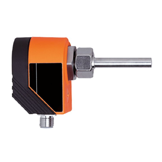
Efector300 strömungssensor
analog

Verwandte Anleitungen für ifm SI1004


Inhaltszusammenfassung für ifm SI1004
- Seite 1 Bedienungsanleitung Operating instructions Notice utilisateurs Strömungssensor analog Flow sensor analog Sonde de débit analogique SI1004 SI1104...
- Seite 2 Kurzanleitung • Installieren Montage → Seite 6, elektrischer Anschluß → Seite 8. • HI-Abgleich Schalten Sie die Betriebsspannung ein. Nach etwa 15 s ist das Gerät betriebsbereit. Lassen Sie das Medium mit der gewünschten Maximal- strömung (HI) in der Anlage fließen. Drücken Sie die Taste Learn/Set und halten Sie sie gedrückt.
-
Seite 3: Bedien- Und Anzeigeelemente
Bedien- und Anzeigeelemente Einstelltasten MODE / LEARN / ENTER FLOW RATE Betriebsanzeige Betriebsanzeige (Run-Modus) Aktuelle Strömung im Anzeigebereich (grüner LED-Balken) Überströmung (LED 9 blinkt) Unterströmung (LED 0 blinkt) Einstelltasten Mode / Enter: • Anwahl der Menüpunkte und Bestätigung Learn/Set: • Abgleich auf Maximal- / Minimalströmung; •... - Seite 4 Menüstruktur Run-Modus Geräte- Abgleich / funktionen Werkseinstellung (ENTER-Taste) (SET-Taste) Überwachung Überströmung Abgleich Maximalströmung >5...<10s Abgleich Minimalströmung >10...<15s Rücksetzen Werkseinstellung >15...<20s LED = grün LED = orange LED = rot Sachnr. 701887/01...
-
Seite 5: Bestimmungsgemäße Verwendung
Bestimmungsgemäße Verwendung Der Strömungssensor • erfaßt die Strömungsgeschwindigkeit in flüssigen Medien, • setzt sie in ein analoges Ausgangssignal um (4 ... 20 mA), • und zeigt den relativen Strömungswert innerhalb des einstellbaren Erfassungsbereichs durch ein LED-Display an: - LED 0 = unteres Ende des Erfassungsbereichs (Minimalwert / LO) - LED 9 = oberes Ende des Erfassungsbereichs (Maximalwert / HI) •... -
Seite 6: Montage
Montage Das Gerät ist adaptierbar an unterschiedliche Prozeßanschlüsse. (Adapter sind gesondert als Zubehör zu bestellen). • Montieren Sie das Gerät bei waagerecht verlaufenden Rohren möglichst seitlich (Abb 1). Bei Montage von unten sollte die Rohrleitung frei von Ablagerungen sein. Bei Montage von oben sollte die Rohrleitung vollständig mit dem zu überwachenden Medium gefüllt sein. - Seite 7 Gewinde M18 x 1,5 1. Fetten Sie die Überwurfmutter (3) und alle Gewinde mit Schmier- paste ein, um mehrmaliges Lösen und Festziehen zu gewährleisten. Achtung: Es darf kein Fett auf die Sensorspitze (A) gelangen. 2. Schrauben Sie den passenden Adapter (2) auf den Prozeßanschluß (1). 3.
-
Seite 8: Elektrischer Anschluß
Schalten Sie die Anlage spannungsfrei und schließen Sie das Gerät folgendermaßen an: Steckeransicht (am Gerät) n. c. Adernfarben bei ifm-Kabeldosen: 1 = BN (braun), 2 = WH (weiß), 3 = BU (blau), 4 = BK (schwarz) n.c. = nicht belegt Nach dem Einschalten der Versorgungsspannung leuchten alle LEDs auf und verlöschen wieder schrittweise.* Danach ist das Gerät... - Seite 9 Programmieren I I Überwachungsbereich Strömung einstellen HI-Abgleich • Medium mit gewünschter Maximalströmung in der Anlage fließen lassen. • >5...<10 s lang Taste Learn/Set drücken (= Abgleich auf Maximalströmung / oberes Ende des Überwachungsbereichs). Optional: LO-Abgleich Der HI-Abgleich genügt für die meisten wasserbasierten Applikationen.
- Seite 10 I I Verriegeln / Entriegeln Das Gerät läßt sich verriegeln, so daß unbeabsichtigte Fehleingaben verhindert werden: Drücken Sie im Run-Modus 10 s lang die beiden Einstelltasten. Sobald die Anzeige verlischt, ist das Gerät verriegelt oder entriegelt. Auslieferungszustand: Nicht verriegelt. Bei verriegeltem Gerät verlischt die Anzeige kurz, wenn die Mode/Enter-Taste gedrückt wird.
-
Seite 11: Technische Daten
Gehäusewerkstoffe ........PBT-GF 20 Sensorwerkstoff (SI1004). . V4A (1.4404); O-Ring: FPM 8x1,5 gr 80° Shore A Sensorwerkstoff (SI1104) . -
Seite 12: Einstelldiagramme / Technik-Information
Einstelldiagramme / Technik-Information I I Überwachungsbereich Strömung einstellen Der Erfassungsbereich (Fenster) wird festgelegt durch • Abgleich gewünschte Maximalströmung (HI-Teach) = oberes Ende des Fensters. Dieser Abgleich genügt für die Sensor- meisten wasserbasierten signal Applikationen. • Abgleich gewünschte Minimalströmung / Strömungs- stillstand (LO-Teach) = unteres Ende des Fensters;... - Seite 13 • Abgleich auf Minimalströmung / Strömungsstillstand (LO-Teach), optional Das Gerät erfaßt die vorhandene Strömung und setzt diesen Wert als unteren Anzeigewert für das LED-Display. Im Betriebszustand blinkt die erste grüne LED (LED 0), wenn die Strömung unter diesen Wert fällt (bzw. wenn Strömungsstillstand eintritt). ACHTUNG: LO-Teach darf nur nach HI-Teach durchgeführt werden.
- Seite 14 I I Überwachung auf Überströmung Mit dieser Funktion können Sie die Position des Anzeigefensters im Überwachungsbereich festlegen: Verschieben Sie die LED für den obe- ren Anzeigewert auf die Position 8, 7, 6 oder 5. Bei maximaler Betriebsströmung leuchten alle LEDs von 0 bis zu dieser LED. Die LEDs oberhalb dieses Bereichs signalisieren Überströmung.
- Seite 15 Einstellen: Drücken Sie die Taste Mode/Enter einmal. Die aktuelle Einstellung wird angezeigt (grüne LED). Drücken Sie die Taste Learn/Set 5 s lang (bis die LED blinkt). Drücken Sie die Taste Learn/Set so oft, bis die gewünschte LED blinkt. Bei jedem Tastendruck geht die LED eine Position zurück.
- Seite 16 I I Werkseinstellung wieder herstellen (Reset) Drücken Sie die Taste Learn/Set und halten Sie sie gedrückt. Die grünen LEDs rechts und links >15...<20 s blinken, nach 5 s füllt sich der LED-Balken (grün) von links nach rechts, nach weiteren 5 s füllt sich der LED-Balken (grün) von rechts nach links, nach weiteren 5 s füllt sich der...