Exsys EX-11064 Bedienungsanleitung
EX-
EX
EX
-
-
11064 / EX
11064 /
11064 / EX
EX-
-
-
11065
11065
11065
JUMPER SETTING & CONNECTORS
J7:
USB 2.0 - 10 pin connector (Default)
Pin
Signal
Pin
1
2
+5VCC
+5VCC
3
4
1
VCC1 +5V
5
Data1-
Data2-
Data1+
5
6
Data2+
2
VCC2 +5V
6
GND
GND
7
8
3
DATA1-
7
9
10
4
DATA2-
8
Attention!!!
Please make sure that you connect the cable in the right
order like shown in the list above. If you connect the cable
wrong it can destroy your hardware! The labelling on the
cable must match with the ones on our card.
If you use the internal USB A-Port J2, you can use only one
of the ports from the 10 pin connector J7!
HARDWARE INSTALLATION
Attention! If you use Windows ME/ Windows 2000 without service pack 4 or XP without
service pack. Please install the latest service pack first.
If you use Windows 2000 including service pack 4, Windows XP including service pack 3,
Vista, 7 or 8. Or you already installed the drivers please proceed with the following
instructions for hardware installation.
If you are ready with the jumper settings for the EX-11064 / EX-11065, please proceed with the
following installation instructions. Because there are large differences between PC's, we can give
you only a general installation guide for the EX-11064 / EX-11065. Please refer your computer's
reference manual whenever in doubt.
1.
Turn off the power to your computer and any other connected peripherals.
2.
Remove the mounting screws located at the rear and/or sides panels of your Computer and
gently slide the cover off.
3.
If your pc case do have a front panel please follow the instructions at J7 above. Normally
the cables should be marked if not please ask the front panel manufacturer
4.
If necessary please install now the external power supply to the card like shown at JP1 & J6
above.
5.
Locate an available PCI-Express expansion slot and remove its covers from the rear panel of
your computer.
6.
Align the EX-11064 / EX-11065 with the expansion slot, and then gently but firmly, insert the
card. Make sure the card is seated and oriented correctly.
7.
Then connect the card with a screw to the rear panel of the computer.
8.
Gently replace your computer's cover and the mounting screws.
DRIVER INSTALLATION
All OS
After the hardware installation, the operating system will recognize the device automatically and
install the drivers.
CHECK INSTALLED DRIVER
Open the >Device manager< . Now you should see at „USB-Controller" the following new
entry's:
If you see this or a similar information the device is installed correctly.
5
English
English
English
EX
EX-
EX
-
-
11064 /
11064 / EX
11064 / EX
DRIVER INSTALLATION
NEC Drivers (optional)
If you experience any performance problems or if you want to use older operating systems
which doesn't support USB 2.0 such as Windows 98SE. You can download the driver at our
Signal
Pin
Signal
website www.exsys.ch. Then you can install the optional NEC Drivers as follows.
DATA1+
9
NC
Open and run the file "U2v2_1.exe" by double click on your mouse and follow the setup pro-
DATA2+
10
NC
gram to finish installation process. After that shut down windows and follow the instructions for
GND1
the Hardware installation. After installing the card simply start your computer and the card will
GND2
be recognized automatically by your system.
EX-
-
-
11065
11065
11065
6
English
English
English
Bedienungsanleitung
Bedienungsanleitung
Vers. 2.3 / 08.03.13
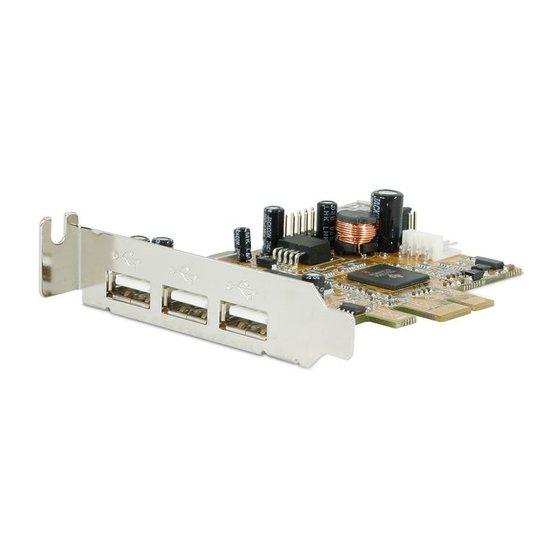
AUFBAU
J7: 2 x interner 10pin USB Port
J3-J5:
3 x externe
USB 2.0 A-Buchse
BESCHREIBUNG & TECHNISCHE DATEN
Die EX-11064 / EX-11065 ist eine USB 2.0 PCI-Express Karte. Sie ist mit 3 externen und 2
internen Ports (eine interne A-Buchse und ein 10Pin Stecker für Frontpanels) ausgestattet. Sie
unterstützt alle PCI-Express Slots von x1 bis x16. Der serielle PCI-Express Bus unterstützt
optimal die Leistung des schnellen NEC Chipset. Die EX-11064 / EX-11065 gewährleistet so
eine sichere Datenübertragung und exzellente Performance von bis zu 480Mbit pro Sekunde!
Es ist nicht möglich die I/O Adressen und Interrupts manuell einzustellen, da die Einstellungen
der Karte vom System (BIOS) und beim installieren des Betriebssystems automatisch vorge-
nommen werden. Bei der EX-11065 handelt es sich um eine LowProfile Karte mit 8cm Bügel für
schmale Gehäuse.
Kompatibilität:
PCI-Express x1 bis x16
Betriebssysteme:
Windows ME/ 2000/ XP/ Vista/ 7/ 8/ Server 20xx/ MAC/ (Linux vom OS)
Anschlüsse:
3x USB A-Buchse extern, 1x USB A-Buchse intern, 1x 10 Pin Stecker
Lieferumfang:
EX-11064 oder EX-11065, Anleitung
Zertifikate:
CE CE CE CE / FCC / RoHS / WEEE
JUMPER EINSTELLUNG & ANSCHLÜSSE
JP1:
PCI = Strom vom PCI-Express BUS (Werkseinstellung)
P=PCI
AUX = Strom vom PC-Netzteil des Rechners
A=AUX
(Zur Entlastung des Mainboards und zur stabilen Stromversorgung
bei Verwendung von Endgeräten mit hohem Stromverbrauch).
Anschluss J6 muss mit PC-Netzteil verbunden werden!
J6:
1 +5V
Wenn JP1 auf AUX gestellt ist, muss J6 mit dem Stromanschluss vom
2 GND
PC Netzteil verbunden werden! Bitte auf die richtige Polarität achten!
3 GND
Achtung! Stecker nie bei eingeschaltetem PC ein oder ausstecken!
4 +12V
J2-J5:
USB 2.0 Pin's
Pin
J2: 1 x interne
für Frontpanel Anschluss
USB 2.0
A-Buchse
JP1:
Stromquelle wählen
PCIe oder AUX
J6:
Anschluss für Stecker
vom PC-Netzteil
PCI-Express Bridge
NEC Chipset
DE97424562 / WHQL
Achtung!
Signal
Sollten Sie beide internen
1
VCC
Anschlüsse von J7
verwenden, können Sie
2
DATA-
die interne USB A-Buchse
3
DATA+
J2 nicht verwenden!
4
GND
1

Verwandte Anleitungen für Exsys EX-11064


Inhaltszusammenfassung für Exsys EX-11064
- Seite 1 NEC Chipset instructions for hardware installation. If you are ready with the jumper settings for the EX-11064 / EX-11065, please proceed with the BESCHREIBUNG & TECHNISCHE DATEN following installation instructions. Because there are large differences between PC’s, we can give you only a general installation guide for the EX-11064 / EX-11065.
- Seite 2 Beachten Sie bitte die folgenden Installationshinweise. Da es große Unterschiede zwischen PC‘s The EX-11064 / EX-11065 is a plug & play high-speed USB 2.0 expansion card for the PCI- gibt, können wir Ihnen nur eine generelle Anleitung zum Einbau der EX-11064 / EX-11065 geben.