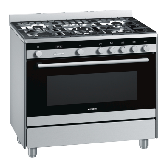
Inhaltszusammenfassung für Siemens HQ738256E
- Seite 1 *9000887264* 9000887264 941015 914775372 Ú Installation instructions Þ Notice de montage Ø Montageanleitung é Installatievoorschrift...
-
Seite 4: Sicherheitshinweise
Typenschild Die technischen Daten des Gerätes finden Sie auf dem Typen- Ø schild. Montageanleitung Sicherheitshinweise Das Typenschild befindet sich auf der Innenseite der Klappe Diese Anleitung sorgfältig lesen und aufbewahren. Nur bei fach- des Aufbewahrungsfaches. gerechtem Einbau entsprechend dieser Montageanleitung ist Die Einstellwerte sind auf einem Aufkleber auf der Geräteverpa- die Sicherheit beim Gebrauch garantiert. -
Seite 5: Gasart Umstellen
Elektroanschluss Gasanschlussleitung mit zylindrischem Gewinde (EN ISO 228 G1/2) - Bild 6b Nur ein konzessionierter Fachmann darf das Gerät anschließen. Verwenden Sie nur Anschlussleitungen oder flexible Schläuche, Das Gerät muss gemäß der neuesten IEE-Richtlinien (Institution die den geltenden Vorschriften entsprechen und für diesen of Electrical Engineers) installiert werden. -
Seite 6: Positionieren Und Ausrichten
Allgemeine Düsentabelle Gasart mbar Düse Brennertyp Leistung Leistung Verbrauch max. min. (W) Nummer Bypass Erdgas - NG 115 (Y) Spalt Starkbrenner 3000 283 l/h 97 (Z) Spalt Normalbrenner 1800 167 l/h 72 (X) Spalt Sparbrenner 1000 97 l/h 135 (S) Spalt Wokbrenner 3900... -
Seite 7: Safety Precautions
Rating plate The technical data for the appliance can be found on the rating Ú plate. Installation instructions Safety precautions The rating plate is located on the inside of the storage Read and store these instructions carefully. Safe use can only compartment flap. -
Seite 8: Electrical Connection
Electrical connection Gas connecting line with cylindrical thread (EN ISO 28 G1/2) - Fig. 6b The appliance must only be connected to the power supply by a Only use connecting cables or flexible hoses which comply with licensed professional. The appliance must be installed in the applicable regulations and which are approved for this accordance with the most recent IEE guidelines (Institute of purpose. -
Seite 9: Positioning And Levelling
General nozzle table Type of gas mbar Nozzle Type of burner Power Power Max. consumption min. (W) Number Bypass Natural gas - 115 (Y) High output burner 3000 283 l/h 97 (Z) Standard burner 1800 167 l/h 72 (X) Economy burner 1000 97 l/h 135 (s) -
Seite 10: Consignes De Sécurité
Plaque signalétique Les caractéristiques techniques de l'appareil sont indiquées sur Þ la plaque signalétique. Notice de montage Consignes de sécurité La plaque signalétique est située à la face intérieure du volet du Lire attentivement cette notice et la conserver soigneusement. compartiment de rangement. -
Seite 11: Raccordement Électrique
Raccordement électrique Tuyau d'arrivée du gaz avec filetage cylindrique (EN ISO 228 G1/2) - fig. 6b Seul un spécialiste agréé est habilité à raccorder l'appareil. Utilisez exclusivement des conduites de raccordement ou des L'appareil doit être installé conformément aux dernières tuyaux flexibles qui répondent aux prescriptions en vigueur et directives IEE (Institution of Electrical Engineers). - Seite 12 Tableau général des injecteurs Type de gaz mbar Injecteur Type de brûleur Puissance Puissance Consommation max. min. (W) Numéro Bypass Gaz naturel - 115 (Y) Ecartement Brûleur rapide 3000 283 l/h 97 (Z) Ecartement Brûleur semi-rapide 1800 167 l/h 72 (X) Ecartement Brûleur auxiliaire 1000 97 l/h...
-
Seite 13: Veiligheidsvoorschriften
Typeplaatje U vindt de technische gegevens van het apparaat op het é typeplaatje. Installatievoorschrift Veiligheidsvoorschriften Het typeplaatje bevindt zich aan de binnenkant van de klep van Lees deze gebruiksaanwijzing zorgvuldig door en bewaar hem het opbergvak. goed. Alleen als de inbouw op deskundige wijze en conform dit De instelwaarden staan aangegeven op een sticker op de installatievoorschrift wordt uitgevoerd, is de veiligheid bij het apparaatverpakking. -
Seite 14: Elektrische Aansluiting
Elektrische aansluiting Gasaansluitleiding met cilindrische schroefdraad (EN ISO 228 G1/2) - Afb. 6b Alleen een daartoe bevoegd vakman mag het toestel aansluiten. Gebruik alleen aansluitleidingen of flexibele slangen die voldoen Het apparaat dient volgens de nieuwste IEE-richtlijnen aan de geldende voorschriften en voor dit doel zijn toegelaten. (Institution of Electrical Engineers) te worden geïnstalleerd. -
Seite 15: Positoneren En Uitrichten
Algemene koppentabel Type gas mbar Brandertype Vermogen Vermogen Verbruik max. min. (W) Nummer Bypass Aardgas - NG 115 (Y) Spleet Sterke brander 3000 283 l/h 97 (Z) Spleet Normale brander 1800 167 l/h 72 (X) Spleet Spaarbrander 1000 97 l/h 135 (S) Spleet Wokbrander...


