Herunterladen Diese Seite drucken
Dimplex Smart-RTC+ RTM Econ A Montageanleitung Und Bedienungsanleitung

Dimplex Smart-RTC+ RTM Econ A Montageanleitung Und Bedienungsanleitung

Raumtemperaturregelung smart-rtc+ zum anschluss an den wärmepumpenmanager
Vorschau ausblenden Andere Handbücher für Smart-RTC+ RTM Econ A:

Werbung

Verfügbare Sprachen

Verfügbare Sprachen

Smart-RTC+
RTM Econ A
RTM Econ U
Raumtemperatur-
regelung
Smart-RTC+ zum
Anschluss an den
Wärmepumpen-
manager
Bestell-Nr. / Order no. / N
Smart-RTC+ room
temperature
control for
connection to the
heat pump
manager
o
de commande : 452115.66.39
Montage- und
Gebrauchsanweisung
Installation and
Operating Instruction
Instruction d'installation
et d'utilisation
Régulation de la
température
ambiante Smart-
RTC+ à raccorder
au gestionnaire
de pompe à
chaleur
DE / EN / FR · FD 9707

Werbung

loading

Inhaltszusammenfassung für Dimplex Smart-RTC+ RTM Econ A

  • Seite 1 Smart-RTC+ Montage- und RTM Econ A Gebrauchsanweisung RTM Econ U Installation and Operating Instruction Instruction d‘installation et d‘utilisation Raumtemperatur- Smart-RTC+ room Régulation de la regelung temperature température Smart-RTC+ zum control for ambiante Smart- Anschluss an den connection to the RTC+ à raccorder Wärmepumpen- heat pump au gestionnaire...
  • Seite 3: Inhaltsverzeichnis

    Smart-RTC+ Deutsch Inhaltsverzeichnis Bitte sofort lesen........................DE-2 1.1 Wichtige Hinweise ..........................DE-2 1.2 Bestimmungsgemäßer Gebrauch ......................DE-2 1.3 Gesetzliche Vorschriften und Richtlinien ..................... DE-2 Verwendungszweck ........................DE-2 Lieferumfang ..........................DE-3 3.1 RTM Econ U ............................DE-3 3.2 RTM Econ A ............................DE-3 Montage ............................
  • Seite 4: Bitte Sofort Lesen

    Deutsch Smart-RTC+ Bitte sofort lesen 1.1 Wichtige Hinweise ACHTUNG! ACHTUNG! Bei der Inbetriebnahme sind die länderspezifischen sowie die Gewährleistung Frostschutzfunktion darf einschlägigen VDE-Sicherheitsbestimmungen, insbesondere VDE0100 Wärmepumpenmanager und die RTM Econ A⁄U nicht spannungsfrei Technischen Anschlussbedingungen geschaltet werden. Energieversorgungsunternehmen (EVU) ACHTUNG! Versorgungsnetzbetreiber zu beachten! An den Klemmen A / B und GND des RTM Econ A⁄U liegt Kleinspannung ACHTUNG!
  • Seite 5: Lieferumfang

    Smart-RTC+ Deutsch Lieferumfang 3.1 RTM Econ U 3.2 RTM Econ A Lieferumfang: Lieferumfang:  RTM Econ U für Unterputzmontage  RTM Econ A für Aufputzmontage  2 Schrauben zur Befestigung in der Unterputzdose  2 Schrauben und 2 Dübel für die Wandmontage ...
  • Seite 6: Rtm Econ A

    Deutsch Smart-RTC+ 4.3 RTM Econ A Abb. 4.4: Abb. 4.3: Abb. 4.5: DE-4 452115.66.39 · FD 9707...
  • Seite 7: Elektrischer Anschluss

    Smart-RTC+ Deutsch 4.4 Elektrischer Anschluss ACHTUNG! Elektrische Installationsarbeiten dürfen nur von einer Elektrofachkraft durchgeführt werden. Vor den elektrischen Anschlussarbeiten auf Spannungsfreiheit prüfen. 4.4.1 Spannungsversorgung Der Anschluss der Spannungsversorgung der RTM Econ A⁄U er- folgt über ein bauseits zu erstellendes 2-adriges Kabel an den Klemmen L und N (1~ /N, 230 V, 50 Hz).
  • Seite 8: Bus-Leitung

    Deutsch Smart-RTC+ 4.4.3 BUS-Leitung Zwischen Wärmepumpenmanager (N1) RTM Econ A⁄U ist eine BUS-Leitung bauseits zu erstellen. Die BUS-Leitung muss als Linienstruktur ausgeführt werden (Abb. 4.11 auf S. 7). Dazu ist ein geschirmtes Kabel 2x 0,25 mm² mit einer maximalen Länge von 500 m zu verwenden. Als GND- Anschluss wird der Kabelschirm verwendet.
  • Seite 9 Smart-RTC+ Deutsch Abb. 4.12: Abb. 4.11: 452115.66.39 · FD 9707 DE-7...
  • Seite 10: Inbetriebnahme

    Deutsch Smart-RTC+ 4.5 Inbetriebnahme 4.5.1 RTM Econ A⁄U HINWEIS Die Inbetriebnahme der RTM Econ A/U, wird wie in Abb. 4.13 auf S. 8 vorgenommen. Dabei ist auf die Reihenfolge zu achten. Die Kann keine Kommunikation hergestellt werden, so muss am Vergabe der Adressen erfolgt wie in Abb.
  • Seite 11: Wärmepumpenmanager

    Smart-RTC+ Deutsch 4.5.2 Wärmepumpenmanager Die Funktion der Raumregelung Smart-RTC+ muss im Menü vom Wärmepumpenmanager aktiviert werden. In das Menü für die Vorkonfiguration gelangt man durch gleichzeitiges Drücken (ca. 5 Sekunden) der Tastenkombi-  nation (ESC) und (MENUE)  Die Vorkonfiguration wird durch die Taste (ESC) verlassen. Vorkonfiguration Vorkonfiguration aller Anlagenkomponenten Einstellbereich...
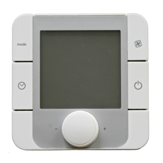
  • Seite 12: Funktionsbeschreibung

    Deutsch Smart-RTC+ Funktionsbeschreibung Abb. 5.1 Beschreibung der Tastenfunktion Wahltaste „Betriebsart“: Wahltaste „Anzeige Raumsolltemperatur“:  Freigabe bzw. Sperre der gewünschten Betriebsart des  Wechsel der Anzeige zwischen der Raumsoll- und aktu- Raumes in dem sich der RTM Econ A⁄U befindet. Diese ellen Raumisttemperatur.
  • Seite 13 Smart-RTC+ English Table of contents Please read immediately ......................EN-2 1.1 Important information ........................... EN-2 1.2 Intended use ............................EN-2 1.3 Legal regulations and directives ......................EN-2 Purpose............................EN-2 Scope of supply ......................... EN-3 3.1 RTM Econ U ............................EN-3 3.2 RTM Econ A ............................
  • Seite 14: Please Read Immediately

    English Smart-RTC+ Please read immediately 1.1 Important information ATTENTION! ATTENTION! During commissioning, observe the respective country-specific safety To ensure that the frost protection function works properly, the heat regulations and the applicable VDE safety regulations, particularly pump manager and the RTM Econ A⁄U must remain connected to the VDE0100 and the technical connection requirements of the utility power supply at all times.
  • Seite 15: Scope Of Supply

    Smart-RTC+ English Scope of supply 3.1 RTM Econ U 3.2 RTM Econ A Scope of supply: Scope of supply:  RTM Econ U for flush mounting  RTM Econ A for surface mounting  2 screws for fixing into the flush mount box ...
  • Seite 16: Rtm Econ A

    English Smart-RTC+ 4.3 RTM Econ A Fig. 4.3: Fig. 4.4: Fig. 4.5: EN-4 452115.66.39 · FD 9707...
  • Seite 17: Electrical Connection

    Smart-RTC+ English 4.4 Electrical connection ATTENTION! Work must only be carried out by qualified personnel. Before carrying out electrical connection work, always ensure that there is no voltage present. 4.4.1 Power supply The power supply is connected to terminals L and N (1~ /N, 230 V, 50 Hz) of the RTM Econ A⁄U via a 2-core cable (to be pro- vided on-site).
  • Seite 18: Bus Line

    English Smart-RTC+ 4.4.3 BUS line A bus line must be connected on-site between the heat pump manager (N1) and the RTM Econ A⁄U. The BUS line must have a linear structure (Fig. 4.11 on page 7). This requires a shielded 2x 0.25 mm²...
  • Seite 19 Smart-RTC+ English Fig. 4.12: Fig. 4.11: 452115.66.39 · FD 9707 EN-7...
  • Seite 20: Commissioning

    English Smart-RTC+ 4.5 Commissioning 4.5.1 RTM Econ A⁄U The RTM Econ A/U is commissioned as shown in Fig. 4.13 on NOTE page 8. The correct sequence must be observed. The addresses If communication cannot be established, the address set on the are allocated as shown in Fig.
  • Seite 21: Heat Pump Manager

    Smart-RTC+ English 4.5.2 Heat pump manager The function of the Smart-RTC+ room control must be activated in the heat pump manager menu. The preconfiguration menu can be accessed by simultaneously pressing (for approx. 5 seconds) the key  combination (ESC) and (MENU). ...
  • Seite 22: Functional Description

    English Smart-RTC+ Functional description Fig. 5.1: Description of the key functions "Operating mode" selector key: "Display room set temperature" selector key:  Release or block of the desired operating mode for the  Changes the display between the room set temperature room where the RTM Econ A⁄U is located.
  • Seite 23 Smart-RTC+ Français Table des matières À lire immédiatement........................FR-2 1.1 Remarques importantes ........................FR-2 1.2 Utilisation conforme ..........................FR-2 1.3 Dispositions légales et directives ......................FR-2 Utilisation.............................FR-2 Fournitures ..........................FR-3 3.1 RTM Econ U ............................FR-3 3.2 RTM Econ A ............................FR-3 Montage ............................FR-3 4.1 Généralités ............................
  • Seite 24: Lire Immédiatement

    Français Smart-RTC+ À lire immédiatement 1.1 Remarques importantes ATTENTION ! ATTENTION ! Lors de la mise en service, il est impératif de respecter les dispositions Pour garantir la fonction de protection antigel, le gestionnaire de pompe de sécurité nationales ainsi que les dispositions de sécurité VDE à...
  • Seite 25: Fournitures

    Smart-RTC+ Français Fournitures 3.1 RTM Econ U 3.2 RTM Econ A Fournitures : Fournitures :  RTM Econ U pour un montage encastré  RTM Econ A pour un montage en saillie  2 vis de fixation dans le boîtier encastré ...
  • Seite 26: Rtm Econ A

    Français Smart-RTC+ 4.3 RTM Econ A Fig. 4.4: Fig. 4.3: Fig. 4.5: FR-4 452115.66.39 · FD 9707...
  • Seite 27: Branchements Électriques

    Smart-RTC+ Français 4.4 Branchements électriques ATTENTION ! Seul un électricien est habilité à effectuer les travaux d'installation électrique. Vérifier l’absence de tension avant de commencer les branchements électriques. 4.4.1 Alimentation en tension Un câble 2 brins fourni par le client et raccordé aux bornes L et N (1~ /N, 230 V, 50 Hz) assure l’alimentation en tension du RTM Econ A⁄U.
  • Seite 28: Câble Bus

    Français Smart-RTC+ 4.4.3 Câble BUS Le client doit prévoir un câble BUS entre le gestionnaire de pompe à chaleur (N1) et le RTM Econ A⁄U. La topologie de ce câble doit être linéaire (Fig. 4.11 - page 7). Pour ce faire, utiliser un câble blindé...
  • Seite 29 Smart-RTC+ Français Fig. 4.12: Fig. 4.11: 452115.66.39 · FD 9707 FR-7...
  • Seite 30: Mise En Service

    Français Smart-RTC+ 4.5 Mise en service 4.5.1 RTM Econ A⁄U REMARQUE La mise en service des RTM Econ A/U s'effectue conformément à la Fig. 4.13 - page 8. Il convient de respecter l'ordre. L'attribu- Si aucune communication ne peut être établie, contrôler l’adresse tion des adresses a lieu comme dans la Fig.
  • Seite 31: Gestionnaire De Pompe À Chaleur

    Smart-RTC+ Français 4.5.2 Gestionnaire de pompe à chaleur La fonction de régulation de la pièce Smart-RTC+ doit être acti- vée dans le menu du gestionnaire de pompe à chaleur. L'accès au menu de pré-configuration se fait en appuyant simultanément (env. 5 secondes) sur les touches ...
  • Seite 32: Description Des Fonctions

    Français Smart-RTC+ Description des fonctions Fig. 5.1:Description du fonctionnement des boutons sélecteurs Bouton sélecteur « Mode de fonctionnement » : Bouton sélecteur « Affichage de la consigne de tem- pérature ambiante » :  Déblocage ou blocage du mode de fonctionnement souhaité...
  • Seite 33: Anhang / Appendix / Annexes

    Smart-RTC+ Anhang · Appendix · Annexes Anhang / Appendix / Annexes Technische Geräteinformationen / Technical Device Information / Informations techniques sur les appareils .................A-II Abmessung / Dimensions / Dimensions..................A-III 2.1 RTM Econ U ............................A-III 2.2 RTM Econ A ............................A-III 452115.66.39 · FD 9707...
  • Seite 34: Technische Geräteinformationen / Technical Device Information / Informations Techniques Sur Les Appareils

    Anhang · Appendix · Annexes Smart-RTC+ 1 Technische Geräteinformationen / Technical Device Information / Informations techniques sur les appareils Spannungsversorgung / Power supply / alimentation en tension 85 bis / to / à 260 V AC, 50/60 Hz Leistungsaufnahme / Power consumption / Puissance absorbée 2 VA Schutzart nach EN 60529 / IP 20...
  • Seite 35: Abmessung / Dimensions / Dimensions

    Smart-RTC+ Anhang · Appendix · Annexes 2 Abmessung / Dimensions / Dimensions 2.1 RTM Econ U 2.2 RTM Econ A 452115.66.39 · FD 9707 A-III...
  • Seite 36 Garantiebedingungen und Kundendienstadresse siehe Mon- Irrtümer und Änderungen vorbehalten. tage- und Gebrauchsanweisung Wärmepumpe. Subject to alterations and errors. Sous réserve d’erreurs et modifications. For the terms of the guarantee and after-sales service addres- ses, please refer to the Installation and Operating Instructions for Heat Pumps.

Diese Anleitung auch für:

Smart-rtc+ rtm econ u