Herunterladen Inhalt Inhalt Diese Seite drucken
Weller WR 2 Betriebsanleitung

Weller WR 2 Betriebsanleitung

Löt- und entlötstation
Vorschau ausblenden Andere Handbücher für WR 2:

Werbung

Verfügbare Sprachen

Verfügbare Sprachen

Weller WR 2 Löt- und Entlötstation
Betriebsanleitung
PK Elektronik Vertriebs GmbH, E-Mail: info@pkelektronik.com, Internet: www.pkelektronik.com

Werbung

Inhaltsverzeichnis
loading

Inhaltszusammenfassung für Weller WR 2

  • Seite 1 Weller WR 2 Löt- und Entlötstation Betriebsanleitung PK Elektronik Vertriebs GmbH, E-Mail: info@pkelektronik.com, Internet: www.pkelektronik.com...
  • Seite 2: Inhaltsverzeichnis

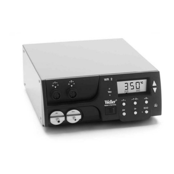
    WR 2 WR 2 Geräteübersicht LED Kanalauswahl LED optische Regelkontrolle LED Vakuum Display UP-Taste DOWN-Taste Kanalwahl-/ Temperaturtasten ┌ 1 ┐, ┌ 2 ┐ Zustandsanzeige LED 17 4 10 Spezialtaste 11 Temperaturtaste ┌ 1·2 ┐ Kanalwahl 12 Heißluft Einstelltaste (Air) 13 Netzschalter 14 Anschluss Vakuum (Vac) 15 Anschluss Heißluft (Air)
  • Seite 3: Zu Dieser Anleitung

    12 Entsorgung ................20 13 Garantie ..................20 1 Zu dieser Anleitung Wir danken Ihnen für das mit dem Kauf der Weller WR 2 erwiesene Vertrauen. Bei der Fertigung wurden strengste Qualitätsanforderungen zugrunde gelegt, die eine einwandfreie Funktion des Gerätes sicherstellen.
  • Seite 4: Zu Ihrer Sicherheit

    Stand der Technik und den anerkannten sicherheitstechnischen Regeln hergestellt. Trotzdem besteht die Gefahr von Personen- und Sicherheitsheft sowie die Warnhinweise in dieser Anleitung nicht beachten. Geben Sie die Reparaturstation WR 2 an Dritte stets zusammen mit der Betriebsanleitung weiter. Bestimmungsgemäßer Gebrauch Verwenden Sie die Reparaturstation WR 2 ausschließlich gemäß...
  • Seite 5: Display

    WR 2 5-20 4 Gerätebeschreibung Die Weller WR 2 ist eine vielseitig verwendbare Reparaturstation für professionelle Reparaturarbeiten an elektronischen Baugruppen neuester Technologie in der industriellen Fertigungstechnik sowie im Reparatur- und Laborbereich. Die WR 2 besitzt 2 unabhängige Kanäle für den gleichzeitigen Betrieb von 2 Lötwerkzeugen.
  • Seite 6 6-20 WR 2 Technische Daten WR 2 Abmessungen L x B x H (mm): 273 x 235 x 102 L x B x H (inch): 10,75 x 9,25 x 4,02 Gewicht ca. 6,7 kg Netzspannung 230 V, 50 Hz (120 V, 60 Hz)
  • Seite 7: Gerät In Betrieb Nehmen

    WR 2 7-20 5 Gerät in Betrieb nehmen Verletzungsgefahr durch falsch angeschlossenen WARNUNG! Vakuumschlauch. Bei falsch angeschlossenem Vakuumschlauch kann bei Betätigen des Entlötkolbens heiße Luft und flüssiges Lötzinn austreten und zu Verletzungen führen. Schließen Sie den Vakuumschlauch nie am „AIR“-Nippel an! 1.
  • Seite 8: Gerät Bedienen

    8-20 WR 2 6 Gerät bedienen Kanal auswählen, ein- oder ausschalten 1. Eine der Tasten ┌ 1 ┐oder ┌ 2 ┐ (7) drücken, um einen der zwei Kanäle auszuwählen. Im Display erscheinen die Soll-Temperatur des angewählten Kanals sowie in kleiner Schrift die fest programmierten Temperaturen.
  • Seite 9: Luftdurchfluss Einstellen

    WR 2 9-20 Temperatur mit Temperaturtasten ┌ 1 ┐, ┌ 1·2 ┐ und ┌ 2 ┐ einstellen Der Temperatursollwert kann für jeden Kanal getrennt durch die Anwahl von drei voreingestellten Temperaturwerten (Festtemperaturen) eingestellt werden. Werkseitige Einstellungen: ┌ 1 ┐ = 150 °C (300 °F), ┌...
  • Seite 10: Löten Und Entlöten

    10-20 WR 2 Löten und Entlöten Führen Sie die Lötarbeiten gemäß der Betriebsanleitung Ihres angeschlossenen Lötwerkzeuges durch. 7 Sonderfunktionen Die Sonderfunktionen sind in 2 Menüebenen eingeteilt: 2 s ➾ Menü 1 − Menü 1 mit Einstellungsmöglichkeiten für Standby-Temperatur, Temperaturabschaltung (Setback), Automatische Abschaltzeit (Auto-OFF), Temperatur-Offset, 4 s ➾...
  • Seite 11 WR 2 11-20 Zurücksetzen der Sonderfunktionen auf die Werkseinstellungen 1. Taste ┌ 2 ┐ drücken und gedrückt halten. 2. Anschließend die Tasten UP und DOWN gleichzeitig drücken. Im Display erscheint „FSE“. Die Reparaturstation ist nun wieder auf die Werkseinstellungen zurückgesetzt.
  • Seite 12: Down-Taste

    12-20 WR 2 1. Menüpunkt OFF im Menü 1 auswählen. 2. AUTO-OFF-Zeitsollwert mit Taste UP oder DOWN einstellen. 3. Mit Taste ┌ 1 ┐ (zurück) oder ┌1·2┐ (vor) zum nächsten Menüpunkt wechseln. 4. Special Button ON/OFF ECO Funktion ON/OFF Temperaturverhalten bei unterschiedlichen Einstellungen der...
  • Seite 13 WR 2 13-20 Temperatur-Offset einstellen Die reale Lötspitzentemperatur kann durch Eingabe eines Temperatur-Offsets um ± 40 °C (± 70 °F) angepasst werden. 1. Menüpunkt OFFSET im Menü 1 auswählen. 2. OFFSET-Temperaturwert mit Taste UP oder DOWN einstellen. 3. Mit Taste ┌ 1 ┐ (zurück) oder ┌1·2┐ (vor) zum nächsten Menüpunkt wechseln.
  • Seite 14 14-20 WR 2 Vakuum Einschaltverzögerung (VAC ON) einstellen Um ein vorzeitiges Starten der Pumpe zu verhindern oder um eine definierte Vorwärmzeit der Lötstelle zu gewährleisten, kann eine Einschaltverzögerung von 0 bis 9 s eingestellt werden (Werkseinstellung 0 s: OFF). 1. Menüpunkt VAC ON im Menü 1 auswählen.
  • Seite 15: Sonderfunktionen Menü 2 Auswählen

    WR 2 15-20 Sonderfunktionen Menü 2 auswählen Sonderfunktionen Navigation LEVEL ↑ ┌ 1 ┐ ↓ ┌1·2┐ AUTO CHANNEL SP BUTTON EXIT ┌ 2 ┐ HAP LOCK CH Wechsel HI / LO CONTROL 1. Gewünschten Kanal ┌ 1 ┐, ┌1·2 ┐ oder ┌ 2 ┐ für die Eingabe der Sonderfunktionen auswählen.
  • Seite 16 16-20 WR 2 Kalibrierfunktion (Factory Calibration Check) bedienen Mit der FCC-Funktion können Sie die Temperaturgenauigkeit der Reparaturstation überprüfen und eventuelle Abweichungen ausgleichen. Hierfür muss die Lötspitzentemperatur mit einem externen Temperaturmessgerät und einer dem Lötwerkzeug zugeordneten Temperaturmessspitze gemessen werden. Vor der Kalibrierung muss der entsprechende Kanal angewählt werden.
  • Seite 17: Spezialtaste

    WR 2 17-20 Kalibrierung auf Werkseinstellungen zurücksetzen 1. Menüpunkt FCC im Menü 2 auswählen. 2. Taste ┌ 2 ┐ gedrückt halten. 3. Anschließend Tasten UP und DOWN gleichzeitig drücken. Im Display erscheint „FSE“ (Factory Setting Enabled). Die Reparaturstation ist nun wieder auf die Werkskalibrierung zurückgesetzt.
  • Seite 18: Zurücksetzen Auf Werkseinstellungen

    Kalibrierung auf Werkseinstellungen zurücksetzen Diese Funktion wird unter „7.2 Sonderfunktionen Menü 2 auswählen“, „Kalibrierung auf Werkseinstellungen zurücksetzen“ auf Seite 17 beschrieben. 9 WR 2 pflegen und warten Filter warten Hauptfilter für “VACUUM” und “AIR” regelmäßig auf Verschmutzung kontrollieren und gegebenenfalls erneuern.
  • Seite 19: Netzschalter

    1. Abdeckkappe „VAC“ (14) oder „AIR“ (15) um 45° nach links drehen und abnehmen. 2. Verschmutzten Filter herausziehen und ordnungsgemäß entsorgen. 3. Eine original WELLER- Filterkartusche einsetzen. Hierbei auf den richtigen Sitz der Deckeldichtung achten. 4. Druckfeder einsetzen. 5. Abdeckkappe unter leichtem Druck wieder aufsetzen und um 45°...
  • Seite 20: Zubehör

    20-20 WR 2 11 Zubehör T005 29 200 99 WP 200 Lötset mit Ablage WDH 31, 200 W T005 29 194 99 WP 120 Lötset mit Ablage WDH 10T, 120 W T005 29 181 99 WP 80 Lötkolbenset, 80 W T005 33 125 99 WSP 80 Lötkolbenset, 80 W...
  • Seite 21 WR 2 Operating Instructions PK Elektronik Vertriebs GmbH, E-Mail: info@pkelektronik.com, Internet: www.pkelektronik.com...
  • Seite 22: Hardware Overview

    WR 2 WR 2 Hardware Overview Channel selection LED Visual check LED Vacuum LED Display UP button DOWN button Channel selection / temperature buttons ┌ 1 ┐, ┌ 2 ┐ Status display LED 17 4 10 Special button 11 Temperature button ┌ 1·2 ┐...
  • Seite 23: About These Instructions

        1 About these instructions Thank you for buying our Weller WR 2. We appreciate your business and the confidence you have placed in us. The device has been manufactured in accordance with the most rigorous quality standards, which ensure that the device operates perfectly.
  • Seite 24: For Your Safety

    Always give out the repair station WR 2 to third parties together with the operating instructions. Intended use Repair station WR 2 may only be used for the purpose specified in the operating instructions, i.e.
  • Seite 25: Device Description

    WR 2 5-20 4 Device description Weller WR 2 is a versatile repair station for professional repair work on state-of-the-art electronic subassemblies in industrial manufacturing, repair shops and laboratories. WR 2 has 2 independent channels for the simultaneous operation of 2 soldering tools.
  • Seite 26 6-20 WR 2 Technical data of WR 2 Dimensions L x B x H (mm): 273 x 235 x 102 L x W x H (inches): 10.75 x 9.25 x 4.02 Weight approx. 6.7 kg Mains supply voltage 230 V, 50 Hz (120 V, 60 Hz)
  • Seite 27: Starting Up The Device

    WR 2 7-20 5 Starting up the device Risk of injury due to incorrectly connected vacuum WARNING! hose. If the vacuum hose is incorrectly connected, hot air and liquid solder can escape when the desoldering iron is actuated and cause injuries.
  • Seite 28: Operating The Device

    8-20 WR 2 6 Operating the device Selecting a channel, switching on or off 1. Press one of the ┌ 1 ┐buttons or ┌ 2 ┐ (7) to select one of two channels. The nominal temperature of the selected channel and the hard programmed temperatures are displayed in small font.
  • Seite 29 WR 2 9-20 Setting the temperature with the ┌ 1 ┐, ┌ 1·2 ┐ and ┌ 2 ┐ temperature buttons The setpoint temperature value can be set for each channel separately by selecting three preset temperature values (fixed temperatures). Factory settings: ┌...
  • Seite 30: Special Functions

    10-20 WR 2 Soldering and desoldering Carry out soldering work as directed in the operating instructions of your connected soldering tool. 7 Special functions The special functions are divided into 2 menu levels: 2 s ➾ Menu 1 − Menu 1 with setting options for Standby temperature, temperature...
  • Seite 31 WR 2 11-20 Resetting the special functions to the factory settings 1. Press and hold down button ┌ 2 ┐. 2. Then press the UP and DOWN buttons simultaneously. "FSE" appears on the display. The repair station is now reset to the factory settings.
  • Seite 32 12-20 WR 2 1. Select the menu item OFF in Menu 1. 2. Set the AUTO-OFF setpoint time value with the UP or DOWN button. 3. Change to the next menu option using the ┌ 1 ┐ (back) or ┌1·2┐...
  • Seite 33 WR 2 13-20 Setting the temperature offset The real soldering-tip temperature can be adapted by entering a temperature offset around ± 40 °C (± 70 °F). 1. Select the menu item OFFSET in Menu 1. 2. Set the OFFSET temperature value with the UP or DOWN button.
  • Seite 34 14-20 WR 2 Setting the vacuum ON delay (VAC ON) To prevent premature starting of the pump or to ensure that the soldered joint is preheated for a defined period, a switch-on delay from 0 to 9 s can be set (factory setting 0 s: OFF).
  • Seite 35 WR 2 15-20 Defining the pressure-gauge threshold − This function can be used to define the maintenance interval of the desoldering tool. Here the value in mbar at which the electric pressure gauge issues a warning signal when the intake system is contaminated (LED (3) of the vacuum pump switches from green to red) is defined.
  • Seite 36 16-20 WR 2 Executing the calibration function (Factory Calibration Check) With the FCC function you can check the temperature precision of the repair station and even out possible deviations. For this purpose, the soldering-tip temperature must be measured with an external temperature meter and a temperature measuring tip assigned to the soldering tool.
  • Seite 37 WR 2 17-20 Resetting calibration to factory settings 1. Select the menu item FCC in Menu 2. 2. Press and hold down button ┌ 2 ┐. 3. Then press the UP and DOWN buttons simultaneously. "FSE (Factory Setting Enabled) appears on the display.
  • Seite 38: Resetting To Factory Settings

    This function is described under "7.2 Selecting special functions of Menu 2"Calibrating to factory settings" on page 14. 9 Care and maintenance of WR 2 Servicing the filter Regularly check the main filter for VACUUM” and AIR” and replace if necessary.
  • Seite 39: Error Messages And Error Clearance

    1. Turn the cover cap for "VAC” (14) or "AIR” (15) 45° counterclockwise and remove. 2. Pull out the contaminated filter and dispose of properly. 3. Insert an original WELLER filter cartridge. Make sure that the cover seal is properly seated. 4. Insert pressure spring.
  • Seite 40: Accessories

    20-20 WR 2 11 Accessories T005 29 200 99 WP 200 Soldering set with holder WDH 31, 200 W T005 29 194 99 WP 120 Soldering set with holder WDH 10T, 120 W T005 29 181 99 WP 80 Soldering iron set, 80 W...
  • Seite 41 WR 2 Notice d'utilisation PK Elektronik Vertriebs GmbH, E-Mail: info@pkelektronik.com, Internet: www.pkelektronik.com...
  • Seite 42: Présentation De L'appareil

    WR 2 WR 2 Présentation de l'appareil LED choix du canal LED contrôle optique de régulation LED vide Ecran Touche UP Touche DOWN Touches sélection canal / température ┌ 1 ┐, ┌ 2 ┐ 17 4 LED affichage d'état 10 Touche spéciale 11 Touche de température...
  • Seite 43: A Propos De Cette Notice

    Cette notice contient des informations importantes pour effectuer la mise en service de la station de réparation WR 2 en toute sécurité et dans les règles de l'art, l'utiliser, l'entretenir et remédier par vous-mêmes aux dérangements les plus simples.
  • Seite 44: Pour Votre Sécurité

    Remettez toujours la station de réparation WR 2 à un tiers avec sa notice d'utilisation. Usage conforme Utilisez la station de réparation WR 2 en vous conformant...
  • Seite 45: Description De L'appareil

    électroniques de technologie ultra moderne dans le secteur technique de la fabrication industrielle, ainsi que dans le domaine de la réparation et des laboratoires. La station WR 2 possède 2 canaux indépendants pour le fonctionnement simultané de 2 outils de soudage.
  • Seite 46 6-22 WR 2 Caractéristiques techniques WR 2 Dimensions L x l x H (mm) : 273 x 235 x 102 L x l x H (pouces) : 10,75 x 9,25 x 4,02 Poids Env. 6,7 kg Tension de réseau 230 V, 50 Hz (120 V, 60 Hz) Puissance absorbée...
  • Seite 47: Mise En Service De L'appareil

    WR 2 7-22 5 Mise en service de l'appareil Risque de blessures par mauvais raccordement du AVERTISSEMENT ! flexible à vide. Si le flexible à vide n'est pas raccordé correctement, de l'air chaud et de l'alliage à base d'étain liquide peuvent émerger lors de l'actionnement du fer à...
  • Seite 48: Utilisation De L'appareil

    8-22 WR 2 6 Utilisation de l'appareil Sélection, activation ou désactivation d'un canal 1. Appuyer sur l'une des touches ┌ 1 ┐ ou ┌ 2 ┐ (7) pour sélectionner l'un des deux canaux. L'écran affiche la température de consigne du canal sélectionné...
  • Seite 49: Réglage Du Débit D'air

    WR 2 9-22 Réglage de température avec les touches de température ┌ 1 ┐, ┌ 1·2 ┐ et ┌ 2 ┐ La température de consigne peut être réglée individuellement pour chaque canal en sélectionnant trois valeurs de température préréglées (températures fixes).
  • Seite 50: Fonctions Spéciales

    10-22 WR 2 Soudage et dessoudage Effectuez les opérations de soudage conformément à la notice d'utilisation de votre outil de soudage raccordé. 7 Fonctions spéciales Les fonctions spéciales sont réparties sur 2 niveaux de menus : 2 s ➾ Menu 1 −...
  • Seite 51 WR 2 11-22 Réinitialisation des fonctions spéciales par rapport aux réglages usine 1. Appuyer sur la touche ┌ 2 ┐ et la maintenir enfoncée. 2. Presser ensuite simultanément les touches UP et DOWN. L'écran affiche “FSE”. La station de réparation est à présent à nouveau réinitialisée par rapport aux réglages usine.
  • Seite 52 12-22 WR 2 Réglage du temps de coupure automatique (AUTO-OFF) Lorsque l'outil de soudage n'est pas utilisé, le chauffage de l'outil de soudage est coupé au bout du temps AUTO-OFF. La coupure de la température s'effectue indépendamment de la fonction "Setback"...
  • Seite 53 WR 2 13-22 Comportement de la température pour les différents réglages des fonctions SETBACK et AUTO OFF Réglages Comportement de la température sans plaque reposoir commutatrice SETBACK OFF Time Time [1-99 min] [1-999 min] L'outil à souder reste à la température de soudage réglée.
  • Seite 54 14-22 WR 2 Réglage du décalage de température La température réelle de la panne à souder peut être adaptée en entrant un décalage (offset) de température de ± 40 °C (± 70 °F). 1. Sélectionner l'option OFFSET dans le menu 1.
  • Seite 55 WR 2 15-22 Réglage de la temporisation au déclenchement du vide (VAC Off) Afin d'empêcher le colmatage de la panne à dessouder, il est possible de régler une temporisation de coupure du vide entre 0 et 5 secondes (réglage usine 2 secondes).
  • Seite 56 16-22 WR 2 Sélection des fonctions spéciales menu 2 Fonctions spéciales Navigation ↑ LEVEL ┌ 1 ┐ ↓ ┌1·2┐ AUTO CHANNEL SP BUTTON EXIT ┌ 2 ┐ changement HAP LOCK canal HI / LO CONTROL 1. Sélectionner le canal souhaité ┌ 1 ┐, ┌1·2 ┐ ou ┌ 2 ┐ pour l'entrée des fonctions spéciales.
  • Seite 57 WR 2 17-22 Utilisation de la fonction de calibrage (Factory Calibration Check) La fonction FCC vous permet de contrôler la précision de température de la station de réparation et de compenser d'éventuelles déviations. A cet égard, la température de la panne à...
  • Seite 58 18-22 WR 2 Nota Presser la touche ┌ 2 ┐ pour quitter l'option de menu sans modifications (EXIT). 6. Appuyer sur la touche ┌1·2 ┐ (Set) pour valider la valeur. La différence de température est à présent réinitialisée sur 0.
  • Seite 59: Réinitialisation Aux Réglages D'usine

    Cette fonction est décrite au chapitre “7.2 Sélection des fonctions spéciales menu 2”, “Réinitialisation du calibrage aux réglages d'usine” en page 18. 9 Entretien et maintenance du WR 2 Entretien du filtre Contrôler régulièrement l'état d'encrassement du filtre principal “VACUUM” et “AIR” et le remplacer si nécessaire.
  • Seite 60: Messages D'erreur Et Élimination Des Défauts

    45° vers la gauche et le retirer. 2. Retirer le filtre encrassé et le rebuter dans les règles de l'art. 3. Monter une cartouche filtrante WELLER d'origine. Faire ici attention au positionnement correct du joint de couvercle. 4. Monter le ressort de pression.
  • Seite 61: Accessoires

    WR 2 21-22 11 Accessoires T005 29 200 99 WP 200 Kit de soudage avec support WDH 31, 200 W T005 29 194 99 WP 120 Kit de soudage avec support WDH 10T, 120 W T005 29 193 99 WP 120 Fer à souder, 120 W T005 29 181 99 WP 80 Kit fer à...
  • Seite 62: Garantie

    22-22 WR 2 13 Garantie Les recours pour vices de fabrication ne sont plus recevables 12 mois après la livraison à l'acheteur. Cette règle ne s'applique pas aux droits de recours de l'acquéreur conformément aux §§ 478, 479 du code civil allemand.
  • Seite 63 WR 2 – Circuit Diagram PK Elektronik Vertriebs GmbH, E-Mail: info@pkelektronik.com, Internet: www.pkelektronik.com...
  • Seite 64 WR 2 – Exploded Drawing PK Elektronik Vertriebs GmbH, E-Mail: info@pkelektronik.com, Internet: www.pkelektronik.com...

Inhaltsverzeichnis