Inhaltsverzeichnis
Werbung
Quicklinks
HiFi
Zusätzlich erforderliche Unterlagen für den Komplettservice
Additionally required Service Documents for the Complete Service
Service
Manual
Sicherheit
Safety
Materialnr./Part No.
720108000000
Materialnummer/Part Number 720107722500
Änderungen vorbehalten/Subject to alteration • Printed in Germany WÜ
H-S44 0802 • 8002/8012, 8003/8013, 8005/8015
http://www.grundig.com
Service Manual
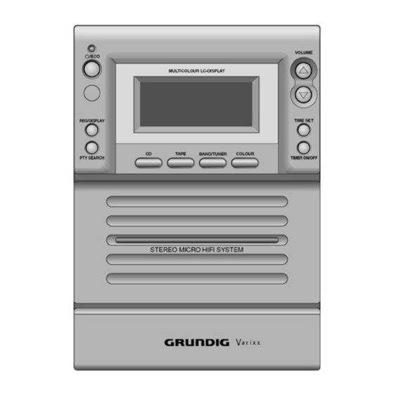
Varixx UMS 4200
GLN0150
Grundig Service
Technik:
TV
TV
SAT
VCR/LiveCam
HiFi/Audio
Car Audio
Telekommunikation
Fax:
Planatron
(8.00-22.00 Uhr)
Ersatzteil-Verkauf:
Telefon:
Fax:
Kundendienst/Werkstätten:
Telefon:
Fax:
gebührenpflichtig
Hotline Deutschland...
...Mo.-Fr. 8.00-18.00 Uhr
0180/52318-41
0180/52318-49
0180/52318-48
0180/52318-42
0180/52318-43
0180/52318-44
0180/52318-45
0180/52318-51
0180/52318-99
Mo.-Fr. 8.00-19.00 Uhr
0180/52318-40
0180/52318-50
Mo.-Fr. 8.00-18.00 Uhr
0180/52318-52
0180/52318-46
Werbung
Inhaltsverzeichnis

Verwandte Anleitungen für Grundig Varixx UMS 4200


Inhaltszusammenfassung für Grundig Varixx UMS 4200
- Seite 1 Service Manual HiFi Varixx UMS 4200 GLN0150 Grundig Service Hotline Deutschland… …Mo.-Fr. 8.00-18.00 Uhr Technik: 0180/52318-41 0180/52318-49 0180/52318-48 Zusätzlich erforderliche Unterlagen für den Komplettservice VCR/LiveCam 0180/52318-42 Additionally required Service Documents for the Complete Service HiFi/Audio 0180/52318-43 Car Audio 0180/52318-44 Service...
-
Seite 2: Inhaltsverzeichnis
Allgemeiner Teil / General Section Varixx UMS 4200 Es gelten die Vorschriften und Sicherheitshin- The regulations and safety instructions shall be weise gemäß dem Service Manual "Sicherheit", valid as provided by the "Safety" Service Manual, Materialnummer 720108000000, sowie zusätz- part number 720108000000, as well as the re-... -
Seite 3: Servicehinweise
Varixx UMS 4200 Allgemeiner Teil / General Section Servicehinweise Service Hints Alle Senderspeicher löschen, zurück auf Werkseinstellungen: Clear all memories, reset to factory default settings: - Gerät vom Netz trennen. - Disconnect unit from mains. - Taste VOL DOWN gedrückt halten und Gerät mit dem Netz verbin- - Hold button VOL DOWN depressed and connect unit to mains. -
Seite 4: Technische Daten
Allgemeiner Teil / General Section Varixx UMS 4200 Technische Daten Technical Data Verstärkerteil Amplifier Unit Ausgangsleistung: Output: Sinusleistung ..............2 x 5W Sine wave power ..............2 x 5W Music power ............... 2 x 8W Musikleistung ..............2 x 8W... -
Seite 5: Ausbauhinweise
Varixx UMS 4200 Allgemeiner Teil / General Section Ausbauhinweise Disassembly Instructions Bevor Sie Leitungen lösen, muss die Leitungsverlegung beachtet Before disconnecting any leads observe the way they are routed. werden. Nach erfolgter Reparatur ist es notwendig, die Leitungs- On completion of the repairs the leads must be laid out as originally fitted at the factory. - Seite 6 Allgemeiner Teil / General Section Varixx UMS 4200 4. Oberteil mit CD-Laufwerk ausbauen 4. Removing Top Cover with CD Drive - Haupt-Platte ausbauen (Pkt. 2). - Remove main board (para 2). - 2 Schrauben (Fig. 8) herausdrehen. - Undo 2 screws (Fig.
-
Seite 7: Cassetten-Laufwerk Ausbauen
Varixx UMS 4200 Allgemeiner Teil / General Section 6. Cassetten-Laufwerk ausbauen 6. Removing Cassette Drive - Gehäuse zerlegen (Pkt. 1). - Disassemble cabinet (para 1). - 4 Schrauben (Fig. 13) herausdrehen. - Undo 4 screws (Fig. 13). - Cassettenfach öffnen und Laufwerk herausnehmen. -
Seite 8: Auf Einen Blick
AUF EINEN BLICK AUF EINEN BLICK _____________________________________________________ ______________________________________________________________________ Die Bedienelemente der HiFi-Anlage STOP Im CD-Betrieb: beendet die Wiedergabe der CD; löscht das Musikprogramm der CD. Bedienelemente an der Oberseite Zum Einstellen der Uhrzeit; SKIP/SEARCH zum Einstellen der Timer-Daten. Kopfhörerbuchse, zum Anschließen eines PHONES TUNING Im Tuner-Betrieb:... - Seite 9 AUF EINEN BLICK AUF EINEN BLICK ______________________________________________________________________ ______________________________________________________________________ Gesamtspieldauer einer CD wird angezeigt. Die Rückseite der HiFi-Anlage TOTAL STEREO ; > < Verbleibende Spielzeit eines Titels oder der REMAIN Wurfantenne für den FM (UKW) - TIMER ON OFF TOTAL REMAIN INTRO SLEEP CD werden angezeigt (während der Empfang.
-
Seite 10: Allgemeine Funktionen
OVERVIEW ALLGEMEINE FUNKTIONEN _______________________________________________________________________ ___________________________ The HiFi system controls Ein- und Ausschalten HiFi-Anlage mit » /ECO« aus Bereitschaft (Stand-by) einschalten. – Die zuletzt aktive Programmquelle wird automatisch gewählt. Controls on the top Hinweis: Headphone jack for connecting a stereo PHONES Zum Einschalten können auch folgende Tasten am Gerät oder an der Fernbe- headphone set with a jack plug dienung verwendet werden:... - Seite 11 OVERVIEW OVERVIEW __________________________________________________________________________________ __________________________________________________________________________________ Controls on the front Switches the timer on and off. TIMER ON/OFF • LED (power-saving mode). VOLUME Adjusts the volume. Switches the HiFi system to and from /ECO TIMER SET Displays the time; stand-by mode; activates the timer setting. VOLUME g/ECO switches on from demo mode;...
-
Seite 12: General Functions
OVERVIEW OVERVIEW __________________________________________________________________________________ __________________________________________________________________________________ The remote control Switches the sleep timer on and off. SLEEP INTRO In CD mode: Switches the HiFi system to and from stand-by mode; switches /ECO for a brief sample playback of each track. on from demo mode; extended pressing: switches the HiFi system to power-saving EQ/UBS g/ECO... -
Seite 13: Abgleichvorschriften
Varixx UMS 4200 Abgleichvorschriften / Adjustment Procedures Abgleichvorschriften Tuner Messgeräte: Mess-Sender, Oszilloskop, Digital-Voltmeter Abgleich Vorbereitung Abgleichvorgang ± 1. AM-Oszillator Mit T202 bei 1602kHz auf 7,5V 0,5V abgleichen. Digital-Voltmeter an Messpunkt TP1. 2. AM-ZF Mit T201 auf NF-Maximum abgleichen. Mess-Sender 450kHz über Loop-Antenne ankoppeln;... -
Seite 14: Adjustment Procedures
Abgleichvorschriften / Adjustment Procedures Varixx UMS 4200 Adjustment Procedures Tuner Test equipment: Signal Generator, Oscilloscope, Digital Voltmeter Adjustment Preparation Adjustment Procedure ± 1. AM Oscillator Adjust with T202 at 1602kHz for 7.5V 0.5V. Digital Voltmeter to Testpoint TP1. 2. AM IF Adjust with T201 for AF Maximum. - Seite 15 Varixx UMS 4200 Abgleichvorschriften / Adjustment Procedures Abgleichlageplan / Alignment Layout GRUNDIG Service 2 - 3...
-
Seite 16: Schaltpläne Und Platinenabbildungen / Circuit Diagrams And Layout Of The Pcbs
Schaltpläne und Platinenabbbildungen / Circuit Diagrams and Layout of the PCBs Varixx UMS 4200 Schaltpläne und Platinenabbildungen / Circuit Diagrams and Layout of the PCBs Blockschaltbild / Block Diagram 3 - 1 GRUNDIG Service... - Seite 17 Varixx UMS 4200 Schaltpläne und Platinenabbildungen / Circuit Diagrams and Layout of the PCBs Varixx UMS 4200 Schaltpläne und Platinenabbildungen / Circuit Diagrams and Layout of the PCBs Verdrahtungsplan / Wiring Diagram GRUNDIG Service 3 - 2 GRUNDIG Service 3 - 3...
- Seite 18 Schaltpläne und Platinenabbildungen / Circuit Diagrams and Layout of the PCBs Varixx UMS 4200 Schaltpläne und Platinenabbildungen / Circuit Diagrams and Layout of the PCBs Varixx UMS 4200 Teilschaltplan Tuner / Circuit Diagram section Tuner S./p. 3-16 S./p. 3-10 S./p. 3-17 S./p.
- Seite 19 Varixx UMS 4200 Schaltpläne und Platinenabbildungen / Circuit Diagrams and Layout of the PCBs Varixx UMS 4200 Schaltpläne und Platinenabbildungen / Circuit Diagrams and Layout of the PCBs Teilschaltplan CD / Circuit Diagram section CD to CN851 S./p. 3-10 to CN104 S./p.
- Seite 20 Schaltpläne und Platinenabbildungen / Circuit Diagrams and Layout of the PCBs Varixx UMS 4200 Schaltpläne und Platinenabbildungen / Circuit Diagrams and Layout of the PCBs Varixx UMS 4200 Teilschaltplan Cassette / Circuit Diagram section Cassette to CN702 S./p. 3-6 S./p. 3-16 S./p.
- Seite 21 Varixx UMS 4200 Schaltpläne und Platinenabbildungen / Circuit Diagrams and Layout of the PCBs Varixx UMS 4200 Schaltpläne und Platinenabbildungen / Circuit Diagrams and Layout of the PCBs Teilschaltplan NF-Teil, Netzteil / Circuit Diagram section AF Part, Power Supply to CN701 S./p.
- Seite 22 Schaltpläne und Platinenabbildungen / Circuit Diagrams and Layout of the PCBs Varixx UMS 4200 Schaltpläne und Platinenabbildungen / Circuit Diagrams and Layout of the PCBs Varixx UMS 4200 Teilschaltplan CPU, Display / Circuit Diagram section CPU, Display to CON4 S./p. 3-14 to CN260 S./p.
- Seite 23 Varixx UMS 4200 Schaltpläne und Platinenabbildungen / Circuit Diagrams and Layout of the PCBs Varixx UMS 4200 Schaltpläne und Platinenabbildungen / Circuit Diagrams and Layout of the PCBs Teilschaltplan Tasten-Platten / Circuit Diagram section Key Boards to CN106 S./p. 3-13 to CN107 S./p.
- Seite 24 Schaltpläne und Platinenabbildungen / Circuit Diagrams and Layout of the PCBs Varixx UMS 4200 Schaltpläne und Platinenabbildungen / Circuit Diagrams and Layout of the PCBs Varixx UMS 4200 U250 / BU1924F U260 / TC9257F IC-Innenschaltbilder / IC Block Diagrams U201 / TA2104BN...
-
Seite 25: Haupt-Platte
Varixx UMS 4200 Schaltpläne und Platinenabbildungen / Circuit Diagrams and Layout of the PCBs Varixx UMS 4200 Schaltpläne und Platinenabbildungen / Circuit Diagrams and Layout of the PCBs Haupt-Platte / Main Board Sicht auf Bestückungsseite View on Component Side Für die tatsächliche Bauteilbestückung ist das Schaltbild maßgebend! -
Seite 26: Key Board
Schaltpläne und Platinenabbildungen / Circuit Diagrams and Layout of the PCBs Varixx UMS 4200 Schaltpläne und Platinenabbildungen / Circuit Diagrams and Layout of the PCBs Varixx UMS 4200 Haupt-Platte / Main Board Tasten-Platte Key Board Sicht auf Lötseite View on Solder Side Sicht auf Bestückungsseite... -
Seite 27: Display Board
Varixx UMS 4200 Schaltpläne und Platinenabbbildungen / Circuit Diagrams and Layout of the PCBs Display-Platte / Display Board Für die tatsächliche Bauteilbestückung ist das Schaltbild maßgebend! The circuit diagram is relevant for the actual component assembly! Sicht auf Bestückungsseite View on Component Side Display-Platte / Display Board Sicht auf Lötseite... -
Seite 28: Cd Board
Schaltpläne und Platinenabbbildungen / Circuit Diagrams and Layout of the PCBs Varixx UMS 4200 CD-Platte / CD Board Sicht auf Bestückungsseite View on Component Side Für die tatsächliche Bauteilbestückung ist das Schaltbild maßgebend! The circuit diagram is relevant for the actual component assembly! -
Seite 29: Front Board
Varixx UMS 4200 Schaltpläne und Platinenabbildungen / Circuit Diagrams and Layout of the PCBs Varixx UMS 4200 Schaltpläne und Platinenabbildungen / Circuit Diagrams and Layout of the PCBs Front-Platte / Front Board Beleuchtungs-Platte / Backlight Board Für die tatsächliche Bauteilbestückung ist das Schaltbild maßgebend! The circuit diagram is relevant for the actual component assembly! Sicht auf Bestückungsseite... -
Seite 30: Exploded View And Spare Parts List
Explosionszeichnung und Ersatzteilliste / Exploded View and Spare Parts List Varixx UMS 4200 Explosionszeichnung und Ersatzteilliste / Exploded View and Spare Parts List Varixx UMS 4200 Explosionszeichnung und Ersatzteilliste Exploded View and Spare Parts List 4 - 1 GRUNDIG Service... -
Seite 31: Ersatzteilliste Spare Parts List
L 00802 759550572800 DR AX8UH WLF800081 C 00819 759550360100 ELKO 3300UF25V20% L 00803 759550572500 SPULE RH03505AS-W4B 7 / 2002 VARIXX UMS 4200 C 00852 759550360100 ELKO 3300UF25V20% L 00804 759550572500 SPULE RH03505AS-W4B C 00913 845209701500 ELKO #39 1000UF +50-20% 2... - Seite 32 POS. NR. MATERIAL-NR. BEZEICHNUNG POS. NR. MATERIAL-NR. BEZEICHNUNG POS. NO. PART NUMBER DESCRIPTION POS. NO. PART NUMBER DESCRIPTION Q 00704 759550570200 TRANS 2SC1383R VD 00201 759550571400 CAP-DIODE SVC348S Q 00705 759825020000 TRANS.2 SA 733 P 8-729-17 VD 00202 759550461400 CAP-DIODE SVC201-SPA Q 00803 759550571100 SMD TRANS 9013G SOT23...