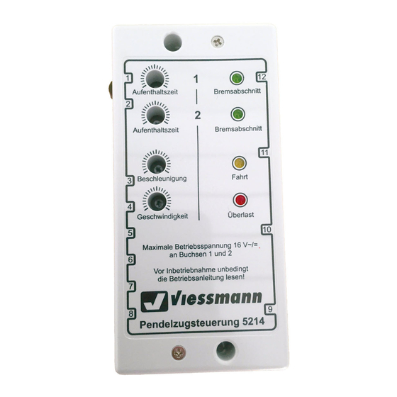
Viessmann 5214 Betriebsanleitung
Pendelzugsteuerung
Vorschau ausblenden
Andere Handbücher für 5214:
- Betriebsanleitung (8 Seiten) ,
- Bedienungsanleitung (8 Seiten) ,
- Bedienungsanleitung (8 Seiten)
Quicklinks
Dieses Symbol bezeichnet stellt einen Moment-Tast-
schalter dar. Der Strom fließt nur so lange, wie der
Taster gedrückt wird.
In den Anschlußplänen dieser Anleitung finden Sie
häufig das obenstehende Symbol. Es kennzeichnet
eine Leitungsverbindung. Die sich hier kreuzenden
Leitungen müssen an einer beliebigen Stelle ihres
Verlaufs elektrisch leitend miteinander in Verbin-
dung stehen. Der Verbindungspunkt muß also nicht
exakt an der eingezeichneten Stelle sitzen, sondern
kann z.B. zu einem Stecker, welcher sich an einer der
kreuzenden Leitungen befindet, verlagert wer-den.
Dieses Symbol neben dem Gleis kennzeichnet eine
in elektrische Trennstelle (z.B. mit Isolierschienen-
verbindern). Diese muß exakt auf der Seite sitzen,
auf welcher Sie eingezeichnet ist.
Achtung!
Anschlußarbeiten nur bei abgeschalteter Betriebsspannung durchführen!
Make sure that the power supply is switched off when you connect the wires
Die Stromquellen müssen so abgesichert sein, daß es im Falle eines Kurz-
schlusses nicht zum Kabelbrand kommen kann. Verwenden Sie nur
handelsübliche und nach VDE/EN gefertigte Modellbahntransformatoren!
The power sources must be protected to prevent the risk of burning wires. Only
use VDE/EN tested special model train transformers for the power supply!
Technische Daten
Technical Data
Betriebsspannung
operating voltage
Maximaler Fahrstrom
maximum drive current
Aufenthaltszeit
stop time
Wir wünschen Ihnen viel Spaß mit Ihrer Modellbahnanlage.
We wish you to have lots of fun with your model railway.
Viessmann
Modellspielwaren GmbH
Am Bahnhof 1
D - 35116 Hatzfeld
www.viessmann-modell.de
8
This sign shows a push button switch with
momentary contact. The current
only
flows while you
push the button.
In the connection diagrams of this instruction you
can often see the above shown symbol. It describes
a wire connection. The wires which here are cros-
sing themselves have to be connected electrically at
any point on their way. So the connection point
doesn't need to be exactly at the shown location. It
can be moved e.g. to a plug which is connected to
one of the crossing wires.
This sign beside the track indicates an electrical
track insulation (e.g. by insulated rail joiners). It must
be placed exactly on the same side on which the
triangle is placed in the picture.
Attention!
!
10 - 16 V =/~
AC/DC
2 A
5 - 70 s
Stand 02
Sachnummer 98663
Viessmann
Modellspielwaren GmbH
Pendelzugsteuerung
Commuter Train Control
Module
5214
Betriebsanleitung
Operating Instructions
D
Dieses Produkt ist kein Spielzeug.
Nicht geeignet für Kinder unter 14
Jahren! Anleitung aufbewahren!
GB This product is not a toy.
Not suitable for children under 14
years! Keep instructions!
F
Ce produit n'est pas un jouet. Ne
convient pas aux enfants de moins
de 14 ans! Conservez cette notice
d'instructions!
gemäß
EG-Richtlinie
89/336/EWG
NL Dit produkt is geen speelgoed. Niet
geschikt voor kinderen onder 14 jaar!
Gebruiksaanwijzing bewaren!
I
Questo prodotto non è un giocattolo.
Non adatto a bambini al di sotto dei 14
anni!
Conservare instruzioni per l'uso!
E
Esto no es un juguete. No
recomendado para menores de 14
años!
Conserva las instrucciones de
servicio!
1

Verwandte Anleitungen für Viessmann 5214


Inhaltszusammenfassung für Viessmann 5214
- Seite 1 Diese muß exakt auf der Seite sitzen, be placed exactly on the same side on which the auf welcher Sie eingezeichnet ist. triangle is placed in the picture. 5214 Achtung! Attention! Anschlußarbeiten nur bei abgeschalteter Betriebsspannung durchführen! Make sure that the power supply is switched off when you connect the wires Die Stromquellen müssen so abgesichert sein, daß...
- Seite 2 Selbiges gilt auch für Dauerzugbeleuchtungs-Generatoren. Fahrt: This yellow LED indicates the voltage at the track. The commuter train control module 5214 allows a train to commute automatically between two Überlast: This red LED lights, if the commuter train control module has switched off stations.
- Seite 3 Sobald das erste stromaufnehmende Fahrzeug die Trennstelle am Viessmann 4199 Beginn des Halteabschnitts passiert hat, beginnt die Pendelzugsteue- rung, den gesamten Zug bis zum Stillstand abzubremsen. Dieses strom- Abbildung 1 Figure 1 aufnehmende Fahrzeug kann einerseits die Lokomotive, andererseits z.B.
- Seite 4 How to connect the commuter train control module with LGB zwingend als LGB ist die Ver- der An- Wichtiger Hinweis! 10*- 16 V ~/= AC/DC wendung schluß ent- Viessmann Wird die dargestellte z.B. Lichttransformator 5200 eines Ori- sprechend LED-bestücktes Viessmann Hand-/Automatikbetriebs- e.g.