
Verwandte Anleitungen für GYS VAS 821 101


Inhaltszusammenfassung für GYS VAS 821 101
- Seite 1 VAS 821 101 2-9 / 10-31 / 98-108 400 V 2-9 / 32-54 / 98-108 2-9 / 55-75 / 98-108 2-9 / 76-97 / 98-108 73502_V2_22/01/2024...
- Seite 2 VAS 821 101 MONTAGE SUPPORT / ASSEMBLY OF SUPPORT / MONTAGE HALTERUNG / MONTAJE DEL SOPORTE M6x16 (x4) 10 N·m M6x16 (x4) 10 N·m MONTAGE SUPPORT CÂBLE/ CABLE SUPPORT ASSEMBLY / MONTAGE DER KABELHALTERUNG / MONTAJE DEL SOPORTE DEL CABLE...
- Seite 3 VAS 821 101 MONTAGE SUPPORT BRAS / ASSEMBLY OF ARM SUPPORT / MONTAGE ARM / MONTAJE DEL SOPORTE PARA BRAZO M5x12 (x4) 6 N·m...
- Seite 4 VAS 821 101 MONTAGE POTENCE / ASSEMBLY OF OVERHANGING ARM / MONTAGE AUSLEGER / MONTAJE DEL SOPORTE GRÚA x2 : M6 x16 x2 : M6 x2 : M8 x 25 x2 : M8 x 25 x1 : M8 x16 x1 : M6 x16...
- Seite 5 VAS 821 101 x3 : M8 x 60 x3 : M8...
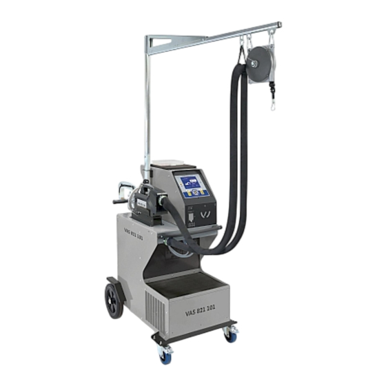
- Seite 6 VAS 821 101 250 cm max. 99 inch max. 14 kg max. 31 lb max. Pour régler la tension du câble de l’équilibreur, l’utilisateur doit impérativement mettre la pince en charge sur le câble. To adjust the tension of the cable in the pulley system, the user must place the clamp on the cable.
- Seite 7 VAS 821 101 x2 : M8 x 20 x2 : M8 x 20 x2 M8x20 20 N·m...
- Seite 8 VAS 821 101...
- Seite 9 VAS 821 101 FIG-1 FIG-2...
- Seite 10 VAS 821 101 AVERTISSEMENTS - RÈGLES DE SÉCURITÉ CONSIGNE GÉNÉRALE Ces instructions doivent être lues et bien comprises avant toute opération. Toute modification ou maintenance non indiquée dans le manuel ne doit pas être entreprise. Veiller à bien conserver ce manuel d’instruction pour des consultations ultérieures.
- Seite 11 VAS 821 101 • Cet équipement de soudage produit des fumées et des gaz qui contiennent des produits chimiques dont l’État de Californie reconnait qu’ils provoquent des malformations congénitales et, dans certains cas, des cancers (code de santé et sécurité de Californie, chapitre 25249.5 et suivants).
- Seite 12 VAS 821 101 RECOMMANDATIONS POUR ÉVALUER LA ZONE ET L’INSTALLATION DE SOUDAGE Généralités L’utilisateur est responsable de l’installation et de l’utilisation du matériel de soudage par résistance suivant les instructions du fabricant. Si des perturbations électromagnétiques sont détectées, il doit être de la responsabilité de l’utilisateur du matériel de soudage par résistance de résoudre la situation avec l’assistance technique du fabricant.
- Seite 13 VAS 821 101 INSTALLATION DU MATÉRIEL • Mettre la source de courant de soudage sur un sol dont l’inclinaison maximum est de 10°. • La source de courant de soudage doit être à l’abri de la pluie battante et ne pas être exposée aux rayons du soleil.
- Seite 14 VAS 821 101 INSTALLATION – FONCTIONNEMENT PRODUIT Seul le personnel expérimenté et habilité par le fabricant peut effectuer l’installation. Pendant l’installation, s’assurer que le générateur est déconnecté du réseau. Les connexions en série ou en parallèle de générateurs sont interdites.
- Seite 15 VAS 821 101 ACCESSOIRES ET OPTIONS Liquide de Housse de protection Carte SD avec Equilibreur 40 caps refroidissement programmes 10>14 kg x 18 x 18 x 10 5 l : 062511 048935 050068 050853 050914 059696 10 l : 052246 Affûteur de caps...
- Seite 16 VAS 821 101 REMPLISSAGE DU RÉSERVOIR DE LIQUIDE DE REFROIDISSEMENT Le liquide de refroidissement recommandé par JBDC, doit impérativement être utilisé : 5 l : ref. 062511 • 10 l : ref. 052246 L’utilisation de liquides de refroidissement autres, et en particulier du liquide standard automobile, peut conduire, par un phénomène d’électrolyse, à...
- Seite 17 AUTO. Pour la VAS 821 101, se mettre systématiquement dans ce mode pour arrêter la pompe lors du changement des bras. L’électrode se rétracte alors dans la pince. Le voyant rouge sur le bouton s’allume signifiant que la pompe est arrêtée.
- Seite 18 VAS 821 101 Ce mode s’affiche par défaut au démarrage de la machine. Mode AUTO Ce mode permet de souder les tôles sans spécifier aucun paramètre à l’écran de la machine. Celle-ci déter- mine elle-même les paramètres de soudage adaptés.
- Seite 19 VAS 821 101 Mode GYSTEEL Le mode GYSTEEL est optionnel; il est configurable dans le menu « Réglages ». Ce mode est identique au mode normal sauf que l’utilisateur saisit la limite élastique des tôles (Re). Cette valeur «Re» peut être connue en utilisant un duromètre tel que le GYSTEEL Vision.
- Seite 20 VAS 821 101 Contrôle daN : Ce réglage permet d’activer ou de contrôler l’effort de serrage de la pince lors d’une soudure. Mode COLLE : Sur l’écran RÉGLAGES ci-dessus, l’utilisateur peut préciser la présence de colle entre les tôles. Si le mode colle est activé, un prépoint est réalisé...
- Seite 21 VAS 821 101 En mode Normal, le pistolet sera limité à des tôles de 1.5 mm maximum. Avec le pistolet, l’opérateur a le choix entre différents outils (mono point, étoile, impact, chauffe rétreinte, goujon, rivet, écrou, molette). La sélection de l’outil se fait avec les touches + et -.
- Seite 22 VAS 821 101 Courant trop faible 1/ Vérifier ligne Si le courant obtenu pendant le point est inférieur à la valeur de consigne (6 %), la machine indique une fois le point effectué un message d’avertissement « Courant faible, vérifier ligne » indiquant que le point est à...
- Seite 23 VAS 821 101 La saisie de l’identifiant se fait avec les 4 touches +, - . Lors de la saisie d’un identifiant déjà utilisé, la machine enregistrera les nouveaux points à la suite, sans effacer les précédents. La touche permet de récupérer un rapport précédemment enregistré et de le relire sur l’écran.
- Seite 24 • Le N° de page est indiqué en haut à gauche. • L’ensemble des ordres de réparation est mémorisé dans le fichier catalog.GYS. • Ce fichier contient le nombre total d’ordres de réparation, le nom de chaque ordre de réparation et le nom de chaque utilisateur. Il y a 100 ordres de réparation au maximum.
- Seite 25 VAS 821 101 MONTAGE ET CHANGEMENT DES BRAS DE LA PINCE Veuillez lire attentivement les consignes qui suivent. Un mauvais serrage ou réglage des bras de la pince en C peut entraîner une surchauffe importante du bras et de la pince et les détériorer de manière irrémédiable.
- Seite 26 VAS 821 101 RÉGLAGE DES BRAS DE LA PINCE - Baisser le bouton de blocage qui permet la sur ouverture - Tirer la molette de réglage et la tourner pour qu’elle pose sur la goupille - Serrer la bague crantée à...
- Seite 27 VAS 821 101 CONTRÔLE PÉRIODIQUE DE LA PINCE Le serrage des vis suivantes doit être contrôlé périodiquement (tous les mois) : Vis fixant le support de bras sur le corps de la pince : Ces 4 vis assurent la fixation du support de bras sur le corps de la pince ; leur bon serrage garantit une bonne transmission du courant de soudage.
- Seite 28 VAS 821 101 LOGICIEL GYSPOT SUR PC Ce logiciel à pour objectif d’éditer et de sauvegarder les rapports de points réalisés à l’aide d’un GYSPOT équipé d’un lecteur de carte SD. Pour utiliser ce logiciel, le PC doit être équipé d’un lecteur de carte SD.
- Seite 29 Le mode « Paramétrage de point » permet de proposer à l’utilisateur des points paramétrés par les constructeurs. Ce mode permet aussi à l’utilisateur de configurer ses propres paramètres de soudure. - Insérer la carte SD livrée avec la soudeuse par point VAS 821 101, dans le lecteur de votre PC puis sélectionner le lecteur correspondant dans le menu déroulant Choix lecteur.
- Seite 30 VAS 821 101 4.4 - Supprimer un point paramétré dans le fichier USER : Sélectionner un point paramétré dans la liste puis cliquez sur le bouton à droite de la liste. Raison sociale : JBDC Téléphone : 0243510101 Adresse : Télécopie :...
- Seite 31 VAS 821 101 Vérifier le serrage du mandrin, du mandrin Mauvais serrage du mandrin. porte-étoiles, et l’état de la gaine. Replacer la gaine pour que le refroidissement Echauffement anormal du pistolet Gaine pistolet déchaussée. air parvienne à l’intérieur du pistolet Vérifier que le patin de masse est en contact...
- Seite 32 VAS 821 101 WARNING - SAFETY RULES GENERAL INSTRUCTIONS Read and understand the following safety instructions before use. Any modification or updates that are not specified in the instructions manual should not be undertaken. Please store this manual safely. The manufacturer is not liable for any injury or damage due to a non-compliance with the instructions featured in this manual.
- Seite 33 VAS 821 101 • This welding equipment produces fumes and gases that contain chemicals considered by the State of California as a source of congenital malformations and potentially, cancers (refer to the California Health Code, chapter 25249.5 and after). • This equipment contains chemicas, including lead, identified by the state if California as a potential cause of cancers and congenital malformations or other issues in relation to procreation.
- Seite 34 VAS 821 101 RECOMMENDATIONS FOR WELDING AREA ASSESSMENT AND WELDING Miscellaneous The user is responsible for the correct installation and usage of the welding material based on the instructions supplied by the manufacturer. If electromagnetic disturbances are detected, it is the user’s responsibility to resolve the situation with the manufacturer’s technical assistance. In some cases, this corrective action may be as simple as earthing the welding circuit.
- Seite 35 VAS 821 101 MAINTENANCE / RECOMMENDATIONS • The operators must have received suitable training in order to use the machine at its maximum potential and weld correctly. • Check which welding process is authorised by the manufacturer before attempting any vehicle repair.
- Seite 36 VAS 821 101 INSTALLATION – PRODUCT OPERATION Only qualified personnel authorised by the manufacturer should perform the installation of the welding equipment. During the installation, the operator must ensure that the machine is disconnected from the mains. Connecting generators in serial or in parallel is forbidden.
- Seite 37 VAS 821 101 ACCESSORIES AND OPTIONS Coolant Protective cover SD card inclu- Overhanging balan- 40 caps ding automatic cing system x 18 x 18 x 10 programs 10>14 kg 5 l: 062511 048935 050068 050853 050914 059696 10 l: 052246...
- Seite 38 VAS 821 101 REFILL OF THE COOLING LIQUID TANK The cooling liquid recommended by JBDC must be used: 5 l: ref. 062511 • 10 l : ref. 052246 The use of other cooling liquids, especially standard automotive liquid, can lead, through electrolysis, to the accumulation of solid deposits in the coo- ling system, reducing the cooling, and may even lead to system block.
- Seite 39 2 seconds to return to the AUTO mode. For the VAS 821 101,, always ensure to be in that mode to stop the pump when changing the arms. The electrode retracts into the clamp. The red indicator on the button lights up when the pump stops.
- Seite 40 VAS 821 101 In order to use this mode, do a blank spot weld (without any sheet/panel between the electrodes),as prompted on the display. Push the button. The message «Do a spot without a load» is displayed on the screen. Push the button again to calibrate. Once the calibration is done, the machine shows all the settings to zero, and is ready to weld.
- Seite 41 VAS 821 101 MANUFACTURER The MANUFACTURER mode is optional; it can be modified using the « Settings» menu. mode This mode is used to name a pre-registered spot based on the repair book issued by the manufacturer. Spot welds programmed by the user can be recalled by selecting USER in the manufacturers list. Welding spots can be programmed using the GYSPOT software and the welding spots settings module.
- Seite 42 VAS 821 101 GLUE mode: On the SETTINGS screen below, the user can specify the presence glue between the panels/sheets. When this mode is in use, a pre-spot is performed before the weld. The duration of this pre-spot is set in milliseconds, from 0 to 400 ms, with 50 ms thresholds. When the glue mode is selected, la word «...
- Seite 43 VAS 821 101 In Manual mode, the maximum possible intensity is 8 kA for a maximum duration of 500 ms. The settings showing on the screen will not exceed these values. Set the generator by indicating the thickness of the sheet/panel to weld using + and - keys. It is possible to adjust the current and time settings when in manual mode.
- Seite 44 VAS 821 101 Insufficient air pressure If the input pressure is insufficient to deliver the tightening requested, the machine beeps and displays, before the weld, the error message «Insufficient air pressure». Pressing the trigger a second time is used to «force» the spot weld using the available pressure.
- Seite 45 VAS 821 101 Identification mode If the identification mode is set to «ON», all mandatory fields in the repair order must be entered to allow the weld to go ahead or the machine will display «identification fault». To activate and deactivate the identification mode, an SD identification card must be inserted in the BP card reader instead of the SD card containing the programs.
- Seite 46 • The page number is indicated at the top left.. • All repair orders are stored in the file called catalog.GYS. • This file contains the total number of repair orders, the name of each repair order and the name of each user. There is a maximum of 100 repair orders.
- Seite 47 VAS 821 101 - Disconnect the cooling liquid pipes and unlock the lever. - Remove the clamp arm. - Lubricate both a new arm and the support with contact grease (ref.050440). Specific Installation for C2 and C8 arms For these arms, the Stretches will also need to be changed. Unscrew the short stretches with a flat spanner and remove the injector.
- Seite 48 VAS 821 101 - Tighten the lever manually and check it is not end up against the joint stop (see diagram below). If it is the case go back to step previous. Warning: Clamp and arm may be damaged if the lever is not tightened properly.
- Seite 49 VAS 821 101 CONNEXION GYSPOT / C CLAMP : B : Black G : Green W : White Y : Yellow THE GYROSCOPE Fix the gyroscope with 4 screws M5 x 12. It can rotate around the clamp at a 360° angle.
- Seite 50 VAS 821 101 3 - Traceability By default, the GYSPOT software opens in «Traceability» mode. In «Point Setting» mode, click on Traceability in the Options menu. 3.1 - Importing point reports from an SD card : To import the point reports made with a GYSPOT into your PC, insert the SD card into the card reader on your PC and start the GYSPOT software.
- Seite 51 VAS 821 101 Then double-click in the second column to select a manufacturer file previously downloaded from our website. The list of spots set by the manufacturer is displayed in the second list. Select a configured point to view the chronogram and configured parameters.
- Seite 52 VAS 821 101 SAFETY AND MAINTENANCE User training People operating this machine must receive suitable training in order to get the most out of the machine capabilities and carry out good quality repairs (examples: car body work training). Preparation of the parts to be assembled It is essential to clean and accost the area to be welded.
- Seite 53 VAS 821 101 SICHERHEITSANWEISUNGEN ALLGEMEIN Lesen Sie vor Inbetriebnahme des Gerätes die Anleitung sorgfältig durch. Nehmen Sie keine Wartungarbeiten oder Verände- rungen am Gerät vor, wenn diese nicht explizit in der Anleitung gennant werden. Bewahren sie diese Bedienungsanleitung sorgfältig auf.
- Seite 54 VAS 821 101 Achtung! Bei Schweißarbeiten in kleinen Räumen müssen Sicherheitsabstände besonders beachtet werden. Beim Schweißen von Blei, auch in Form von Überzügen, verzinkten Teilen, Kadmium, «kadmierte Schrauben», Beryllium (meist als Legierungsbestandteil, z.B. Beryllium-Kupfer) und andere Metalle entstehen giftige Dämpfe. Erhöhte Vorsicht gilt beim Schweißen von Behältern. Entleeren und reinigen Sie diese zuvor. Um die Bildung von Giftgasen zu vermeiden bzw.
- Seite 55 VAS 821 101 Alle Schweißer sollten gemäß dem folgenden Verfahren die Exposition zu elektromagnetischen Feldern aus Schweißgeräten minimieren : • Elektrodenhalter und Massekabel bündeln, wenn möglich machen Sie sie mit Klebeband fest; • Achten Sie darauf, dass ihr Oberkörper und Kopf sich so weit wie möglich von der Schweißarbeit entfernt befinden;...
- Seite 56 VAS 821 101 AUFSTELLUNG • Stellen Sie das Gerät ausschließlich auf festen und sicheren Grund, dessen Neigungswinkel nicht größer als 10° ist und sichern Sie es gegen weg rollen. • Schützen Sie das Gerät vor Regen und direkter Sonneneinstrahlung. • Das Gerät ist IP20-Schutzart konform, d. h: - das Gerät schützt die eingebauten Teile vor Berührungen und mittelgroße Fremdkörpern mit einem Durchmesser >12,5 mm,...
- Seite 57 VAS 821 101 AUFBAU UND FUNKTION Das Gerät darf nur von qualifizierten und befugten Personen montiert und in Betrieb genommen werden. Der Aufbau darf nur im ausgeschalteten, nicht angeschlossenen Zustand vorgenommen werden. Serien- oder Paralellanschlüsse von Generatoren sind untersagt. BESCHREIBUNG (ABB.1) Diese Anlage wurde konzipiert, um folgende Funktionen bei Karosseriereparaturen zu erfüllen:...
- Seite 58 VAS 821 101 ZUBEHÖR UND OPTIONEN Kühlmittel Schutzhaube SD-Karte mit Federbalancer 40 Kappen Programmen 10>14 kg x 18 x 18 x 10 5 l : 062511 048935 050068 050853 050914 059696 10 l : 052246 Elektrodenkappenschleifer Kraftsensor Schweißtestkoffer Europax Rostschutzpaste...
- Seite 59 VAS 821 101 BEFÜLLUNG DES KÜHLMITTELTANKS Das von JBDC empfohlene Kühlmittel muss verwendet werden : 5 l : Art.-Nr. 062511 • 10 l : Art.-Nr. 052246 Die Verwendung anderer Kühlflüssigkeiten, insbesondere von Standardkühlflüssigkeiten, kann wegen der Elektrolyseprozesse zur Bildung von festen Substanzen innerhalb des Kühlkreislaufes führen, die der Effizienz der Kühlung schaden und unter Umständen zum Totalausfall des Systems durch...
- Seite 60 VAS 821 101 2 Speichern von Berichten 5 Anzeige Blechstärke Eine ausführliche Beschreibung zu dieser Funktion finden Sie in einem separaten Kapitel dieser Betriebsanleitung. Die angewählte Stärke der zu schweißenden Bleche wird angezeigt. Die «BERICHT» Taste dient zur Aktivierung / Deaktivierung der Die Auswahl erfolgt über die + und - Pfeiltasten innerhalb der...
- Seite 61 VAS 821 101 Standardmäßig ist dieser Modus beim Start der Maschine angezeigt. Dieser Modus ermöglicht auf Basis verschiedener Sensoriken das effektive Schweißen unterschiedlichster AUTO Modus Blechkombinationen ohne vorherige Einstellung der Parameter an der Maschine. Sie bestimmt selbstständig die geeigneten Schweißparameter.
- Seite 62 VAS 821 101 GYSTEEL Modus Der GYSTEEL Modus ist optional. Er kann im Einstellungsmenü aktiviert werden. Dieser GYSTEEL Modus ist ähnlich dem STANDARD Modus, wobei hier der Anwender den „Re-Wert“ des Materials direkt eingibt und sich daraus der Materialtyp ergibt. Der „Re-Wert“ kann durch einen Härteprüfer wie den GYSTEEL VISION ermittelt werden.
- Seite 63 VAS 821 101 Kontrolle daN Mit dieser Einstellung können Sie die Spannkraft der Klemme während einer Schweißung aktivieren oder kontrollieren. KLEBER Modus : Die Einstellung dieser Option dient zur Kompensation von besonderen «Oberflächenrandbedingungen» wie Kleber oder anderen problematischen Beschichtungen auf oder zwischen den zu verschweißenden Blechen. Es wird ein Vorpunkt mit der eingestellten Zeit initiiert der die Beschichtung «freibrennt».
- Seite 64 VAS 821 101 Im STANDARD Modus ist die maximale Blechstärke auf 1.5mm begrenzt. Neben dem einseitigen Stoßpunkten können mit der Monopunktpistole eine Reihe von weiteren Werkzeugen für z.B. diverse Ausbeularbeiten genutzt werden (Schnellausbeulhammer (Stern), Anschweißen von Well- draht, Ausziehbits, Anschweißen von Scheiben, Nieten, Bolzen, Muttern, Rollnaht-Schweißen, Schrumpfen, Tempern, Härten (Kohleelektrode)).
- Seite 65 VAS 821 101 Unzureichender Luftdruck Ist der Eingangsluftdruck zu niedrig, um den korrekten Elektrode- nanpressdruck zu erzeugen, gibt die Maschine ein Tonsignal und die Meldung «Anpressdruck zu niedrig» aus, bevor der Schweißpunkt ausgelöst wird. Erneutes Drücken des Pistolenauslösers zwingt die Maschine, den Schweißpunkt mit dem vorhandenen Druck auszuführen.
- Seite 66 Liste der Displays, die die Eingabe einer Reparaturreihenfolge (JOB) ermöglichen: Wenn bereits eine Reparaturreihenfolge (JOB) angelegt wurde, kann sie auf dem Gerät nicht geändert oder gelöscht werden. Benutzen Sie die GYS- POT Software für PC, um die Reparaturreihenfolge (JOB) zu löschen. Es ist möglich, maximal 100 Reparaturreihenfolgen (JOBS) auf der SD-Karte zu speichern.
- Seite 67 Schweißpunkte abgespeichert werden. Auf dem Display werden die Namen der Reparaturreihenfolge (JOB) und des Anwenders angezeigt. • Die Seitenzahl erscheint oben links. • Die gesamte Reparaturreihenfolge (JOB) ist in der Datei catalog.GYS abgespeichert. • Diese Datei enthält die Gesamtzahl der Reparaturreihenfolgen (JOBS), sowie deren Namen und die der Anwender. Es gibt maximal 100 Reparatur- reihenfolgen (JOBS).
- Seite 68 VAS 821 101 • Schalten Sie die Maschine aus, oder wählen Sie über die ESC-Taste den Montagemo- dus an. • Ziehen Sie den Verriegelungsstift, der die Überöffnung des Arms ermöglicht. • Entfernen Sie die Schnellkuppelungen der Wasseranschlüsse und den Hebel entriegeln.
- Seite 69 VAS 821 101 EINSTELLUNG DES C-BÜGELS • Drücken Sie den Feststellknopf nach unten, der die Überöffnung ermöglicht. • Ziehen Sie das Einstellrad heraus und drehen Sie es so, dass es auf dem Stift (3) aufliegt • Ziehen Sie den Zahnring...
- Seite 70 VAS 821 101 WARTUNG DER C-ZANGE Die Überprüfung der Schrauben sollte regelmäßig, mindestens einmal im Monat erfolgen: Arretierschrauben zwischen Arm und Zangenkörper: Diese 4 Schrauben fixieren die Armaufnahme an der Zange; ihr korrekter Sitrz garantiert einen störungsfreien Stromfluss. Schlechter Sitz der Schrauben kann Grund für einen schlechten Stromfluss sein und im schlimmsten Fall zu irreparablen Schäden an Zange und Arm führen.
- Seite 71 Um die beim Arbeiten mit der Punktschweißmaschine aufgezeichneten Schweißdaten von der SD- Karte auf den PC zu übertragen, legen Sie bitte die Karte in das am Computer angeschlossene Lesegerät und starten die GYS Software. Im Menü wählen Sie das Kartenlesegerät an und klicken auf das Importicon Ist der Import abgeschlossen, werden die geschweißten Punkte nach Kennzeichnung der Anwendungen gruppiert.
- Seite 72 VAS 821 101 Um in das «Parametersatz Erstellungsmodul» zu gelangen, klicken Sie unter «Optionen» auf «Parametersatz erstellen». Dieser Modus ermöglicht die Anwahl von KFZ-Hersteller definierten Schweißparametersätzen, sowie die Erstellung eigener Parametersätze für z.B. spezielle Blechkombinationen. - Stecken Sie die mit der GYSPOT-Punktschweißanlage gelieferte SD-Karte in den Kartenleser Ihres Computers und wählen Sie nach Start der GYSPOT- Software das entsprechende Laufwerk unter «Wechselmedium»...
- Seite 73 VAS 821 101 4.4 - Löschen eines Parametersatzes im «USER-Ordner» : Wählen Sie einen Prametersatz aus der «USER-Liste» und klicken Sie auf rechts neben der Tabelle. Raison sociale : JBDC Téléphone : 0243510101 Adresse : ZI, 134 Bd des Loges Télécopie :...
- Seite 74 VAS 821 101 Überprüfen Sie die Futterhülse und die Futterhülse MP-Pistole oder entsprechendes Aufnahme für Ausbeulsterne sowie deren Zubehör locker. Ummantelungen. Ungewöhnlich starke Erhitzung der Mono- Ersetzen Sie das Gehäuse, damit die Luftküh- punktpistole Defektes Pistolengehäuse. lung das Innere der Pistole erreicht.
- Seite 75 VAS 821 101 ADVERTENCIAS - NORMAS DE SEGURIDAD CONSIGNA GENERAL Estas instrucciones se deben leer y comprender antes de toda operación. Toda modificación o mantenimiento no indicado en el manual no se debe llevar a cabo. Conserve este manual de instrucciones para una consulta posterior.
- Seite 76 VAS 821 101 • Questa attrezzatura di saldatura produce fumi e gasche contengono prodotti chimici che lo stato della California ritiene provochino malformazioni congenite e, in alcuni casi, cancro (codice di salute e sicurezza della California, capitolo 25249.5 e successivi).
- Seite 77 VAS 821 101 RECOMENDACIONES PARA EVALUAR LA ZONA Y LA INSTALACIÓN DE SOLDADURA Generalidades El usuario se responsabiliza de instalar y usar el aparato siguiendo las instrucciones del fabricante. Si se detectan alteraciones electromagnéticas, el usuario del material de soldadura por resistencia debe resolver la situación siguiendo las recomendaciones del manual de usuario o consultando el servicio técnico del fabricante.
- Seite 78 VAS 821 101 Los cables de alimentación, de prolongación y de soldadura deben estar completamente desenrollados para evitar cualquier sobrecalentamiento. El fabricante no asume ninguna responsabilidad respecto a daños provocados a personas y objetos debido a un uso incorrecto y peligroso de este aparato.
- Seite 79 VAS 821 101 INSTALACIÓN - FUNCIONAMIENTO DEL PRODUCTO Solo el personal experimentado y habilitado por el fabricante puede efectuar la instalación. Durante la instalación, asegúrese que el generador está desconectado de la red eléctrica. Las conexiones en serie o en paralelo del generador están prohibidas.
- Seite 80 VAS 821 101 ACCESORIOS Y OPCIONES Liquido de refrigeración Funda de protección Tarjeta SD con Balanceador 40 caps programas 10>14 kg x 18 x 18 x 10 5 l : 062511 048935 050068 050853 050914 059696 10 l : 052246...
- Seite 81 VAS 821 101 LLENADO DEL TANQUE DE LÍQUIDO DE REFRIGERACIÓN Es imprescindible utilizar el líquido de refrigeración recomendado por JBDC. 5 l : ref. 062511 • 10 l : ref. 052246 El uso de otros líquido de refrigeración, y en particular de líquido estándar para automóviles, puede provocar, mediante un fenómeno de electrolisis, la acumulación de depósitos sólidos en el circuito de refrigeración, que disminuyen la calidad de la refrigeración y pueden llegar a obstruir el circuito.
- Seite 82 AUTO. Para el VAS 821 101,, se coloca sistemáticamente en este modo para detener la bomba cuando se realiza el cambio de brazos. El electrodo se retracta en la pinza. El testigo rojo sobre el botón se enciende, lo cual significa que la bomba está...
- Seite 83 VAS 821 101 Este modo se indica por defecto al inicio de la máquina. Modo AUTO Este modo permite soldar las chapas sin especificar ningún parámetro en la pantalla de la máquina. Esta calcula los parámetros de soldadura adaptados. Para poder utilizar este modo, efectúe antes un punto en vacío (sin chapas entre los electrodos), como se requiere en pantalla. Presione el botón. El mensaje «Efectúe un punto en vacío»...
- Seite 84 VAS 821 101 Modo GYSTEEL El modo GYSTEEL es opcional; se configura en el menú «Ajustes». Este modo es idéntico al modo normal salvo que el usuario completa el límite elástico de las chapas (Re). Este valor «Re» se puede conocer utilizando un durómetro como el GYSTEEL Vision.
- Seite 85 VAS 821 101 Control daN Este ajuste permite activar o controlar la fuerza de sujeción de la pinza durante una soldadura. Modo PEGAMENTO: En la pantalla AJUSTES inferior, el usuario puede precisar la presencia de pegamento entre las chapas. Si el modo pegamento está activado, un pre- punto se realiza antes del punto de soldadura.
- Seite 86 VAS 821 101 En modo Normal, la pistola está limitada a chapas de 1.5 mm máximo. Con la pistola, el operador puede elegir entre diferentes herramientas (monopunto, estrella, impacto, calen- tamiento, pernos, remaches, tuerca, rueda). La selección de herramienta se hace con las teclas + y -.
- Seite 87 VAS 821 101 Corriente demasiado baja 1/ Compruebe la red Si la corriente obtenida durante el punto es inferior al valor asignado (6%), la máquina indica una vez realizado el punto un mensaje de advertencia «Corriente débil, compruebe red», que indica que el punto se debe comprobar.
- Seite 88 VAS 821 101 El registro del identificador se realiza mediante las 4 teclas +,- . LCuando se completa un identificador ya utilizado, la máquina registrará los nuevos puntos, sin suprimir los precedentes. La tecla permite recuperar un informe registrado con anterioridad y volverlo a leer en la pantalla.
- Seite 89 • El N° de página se indica en la parte superior izquierda. • El conjunto de órdenes de reparación se memoriza en el archivo catalog.GYS. • Este archivo contiene el nombre total de órdenes de reparación, el nombre de cada orden de reparación y el nombre de cada usuario. Hay 100 ordenes de reparación como máximo.
- Seite 90 VAS 821 101 CAMBIO DE BRAZOS DE LA PINZA EN C Leer atentamente las instrucciones siguientes. Un mal ajuste o reglaje de los brazos de la pinza en C puede ocasionar un sobrecalentamiento importante del brazo y de la pinza y deteriorarlos de manera irreversible.
- Seite 91 VAS 821 101 REGLAJE DE LOS BRAZOS DE LA PINZA EN C • Bajar el pomo de cierre que permite la sobreapertura • Extraiga el pomo de ajuste y gírelo para que se apoye en el pasador • Apriete el anillo dentado con la mano y, a continua- ción, gire el pomo de ajuste...
- Seite 92 VAS 821 101 CONTROL PERIÓDICO DE LA PINZA Se debe controlar muy a menudo que los tornillos estén bien apretados (cada mes): Tornillo que fija el soporte de brazo al cuerpo de la pinza: Estos 4 tornillos aseguran la fijación del soporte de brazo al cuerpo de la pinza, bien apretarlos garantiza una buena transmisión de la corriente de soldadura.
- Seite 93 VAS 821 101 PROGRAMA GYSPOT SOBRE PC Este programa tiene como objetivo editar y registrar los informes de puntos realizados con un GYSPOT que posea un lector de tarjeta SD. Para utilizar este programa, el PC debe poseer un lector de tarjeta SD.
- Seite 94 VAS 821 101 4 - Parámetros de los puntos Para pasar al modo «Parámetros de puntos», haga clic sobre Parámetros de puntos en el menú Opciones. El modo «Parámetros de punto» permite proponer al usuario puntos configurados por los fabricantes. Este modo también permite al usuario configu- rar sus propios parámetros de soldadura.
- Seite 95 VAS 821 101 4.4 - Suprimir un punto configurado en el archivo USER: Seleccione un punto configurado en la lista, luego haga clic sobre el botón en la derecha de la lista. Raison sociale : JBDC Téléphone : 0243510101 Adresse : Télécopie :...
- Seite 96 VAS 821 101 Compruebe el apriete del mandril, del porta Mal apriete del mandril. estrellas y el estado de la funda. Reemplace la funda para que la refrigeración Calentamiento anormal de la pistola Funda de la pistola desgastada. de aire llegue al interior de la pistola Compruebe que el soporte de masa está...
- Seite 97 VAS 821 101 PIÈCES DE RECHANGE / SPARE PARTS / ERSATZTEILE / PIEZAS DE RECAMBIO / ЗАПЧАСТИ / RE- SERVE ONDERDELEN / PEZZI DI RICAMBIO 400 V - 4 m 400 V - 6 m Collier de serrage / Hose clamp / Spannring / Abrazadera de apriete 71195 Circuit protection thermique primaire / Primary thermal protection circuit / Primäre thermische...
- Seite 98 VAS 821 101 C (C1/C2/C3/C5/C7/C8/C12) Caps type A13 (x6) / Type A13 caps (x6) / Kappen Typ A13 (x6) / Tapones tipo A13 (x6) 049987 Bague BS M6 / BS ring M6 / Anillo BS M6 71385 Tuyau C1 / C1 Hose / C1 Schlauch / Manguera C1...
- Seite 99 VAS 821 101 Electrode 4 positions / 4 position electrode / 4-Punkt-Elektrode / Electrodo de 4 posiciones 050617 Tuyau C6 / C6 Hose / C6 Schlauch / Manguera C6 94580 Goupille de blocage / Locking pin / Sperrstift / Pasador de bloqueo...
- Seite 100 VAS 821 101 C 11 Caps incliné 22° (x6) / 22° inclined caps (x6) / 22° geneigte Kappen (x6) / Tapas inclinadas de 22º (x6) 77029 Tuyau / Hose / Schlauch / Manguera 71850/ 175 / 71084-71316 serti 94656 Tuyau / Hose / Schlauch / Manguera 71850/ 230 / 71084-71316 serti...
- Seite 101 VAS 821 101 Bouchon de remplissage / Filling cap / Behälterverschluss / Tapón de envase / Пробка заправочного отверстия / 71327 Vuldop Réservoir 38 litres Tank 38 litres/ Flüssigkeitbehälter 38 Liter / Depósito de 38 litros / 38-литровый бак / Reservoir 38...
- Seite 102 VAS 821 101 Générateur 400 V Circuit carte SD / SD card circuit / SD-Karten-Schaltung / Circuito de la tarjeta SD 97028C Transformateur / Transformator / Transformador / Трансформатор / Transformator 96019 Carte de puissance / Power board / Leistungsplatine / Tarjeta de potencia / Силовая плата / Vermogens printplaat 97027C Carte de commande / Control card / Steuerplatine / Placa de mando / Плата...
- Seite 103 VAS 821 101 Pont de diode BP / Diode bridge / Gleichrichter BP / Puente de diodos BP / Диодный мост BP / Diode brug BP 52194 Contacteur / Contactor / Schütz / Contactor 51131 Filtre régulateur / Regulation filter / Filterregler / Filtro regulador / Фильтр регулятор / Filter 71462 Interrupteur / Switch / Schalterschalter / Interruptor / Переключатель...
- Seite 104 VAS 821 101 SCHÉMAS ÉLECTRIQUE / CIRCUIT DIAGRAM / SCHALTPLÄNE / ESQUEMAS ELÉCTRICOS / ЭЛЕКТРИЧЕСКИЕ СХЕМЫ / ELEKTRISCHE SCHEMA / SCHEMI ELETTRICI...
- Seite 105 VAS 821 101 SPÉCIFICATIONS TECHNIQUES / TECHNICAL SPECIFICATIONS / TECHNISCHE DATEN / ESPECIFICACIONES TÉCNICAS / ТЕХНИЧЕСКИЕ СПЕЦИФИКАЦИИ / TECHNISCHE GEGEVENS / SPECIFICHE TECNICHE PTI-s7 - 400 V Caractéristiques électriques / Electrical specifications / Elektrische Daten / Caracteristicas electricas Tension nominal d’alimentation / Nominal supply voltage / Eingangsspannung 3~ 400 V Fréquence secteur / Mains frequency / Netzfrequenz / Frecuencia / Частота...
- Seite 106 VAS 821 101 1 l/min Débit du liquide de refroidissement / Cooling liquid debit / Kühlflüssigkeitsdurchfluss 0.26 US gpm Perte de charge du fluide de refroidissement / Loss of cooling liquid / Druckverlust der 3 bar ∆p 44 Psi Kühlflüssigkeit 100 daN Force minimale de soudage / Minimum welding force / Min.
- Seite 107 VAS 821 101 Les porteurs de pacemaker ne doivent pas rester à proximité de cet appareil. / People wearing pacemakers are advised to not come close to the machine. / Personen mit Herzschrittmacher müssen nicht in der Nähe dieser Produket bleiben. / Personas utilizando estimuladores cardiacos no deben dejar cerca de este aparato. / Dragers van een pacemaker mogen niet in de buurt van het apparaat verblijven.