Inhaltszusammenfassung für IFM Electronic ASinterface AC014A
Seite 1
Montageanleitung Installation instructions Notice de montage AS-i Modul AS-i module Module AS-i AC014A...
Seite 2
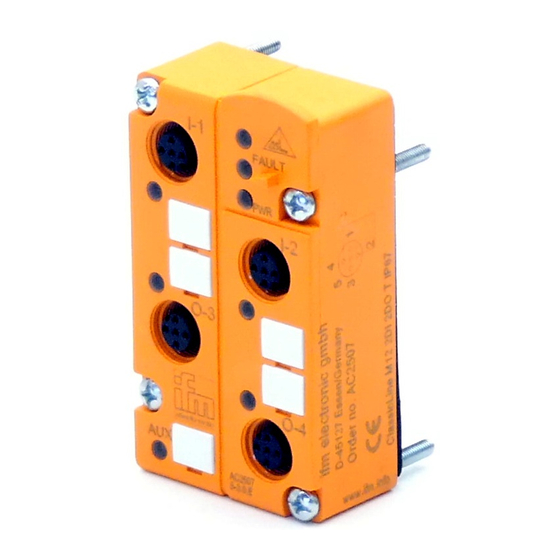
Beachten Sie bei Inbetriebnahme die Hinweise für den Einsatz im Ex-Bereich. Bestimmungsgemäße Verwendung • Das AS-i Modul fungiert als Slave im AS-i-Netz (AS-i-Profil S-B.A.E). Es verbindet zwei Sensoren (2-Draht Sensoren oder PNP-3-Draht Sensoren) sowie zwei Aktuatoren (15 ... 30V DC) mit dem AS-i- Master •...
Seite 4
Adressieren Auslieferungsadresse ist 0. Adressieren mit dem Adressiergerät AC1144 In Verbindung mit dem FK-E-Unterteil AC5003 muß das Modul erst über das Adressiergerät AC1144 adressiert und dann montiert wer- den. Infrarot-Adressierung Das AS-i Modul bietet zusätzlich die Möglichkeit zur Infrarot-Adressie- rung mit dem Adressiergerät AC1144. Die AS-i Kommunikation (gelbes Kabel) muß...
Seite 5
Betrieb Prüfen Sie, ob das Gerät sicher funktioniert. Anzeige durch LEDs: • LED 1 gelb: Eingang /Ausgang geschaltet • LED grün: Spannungsversorgung o.k. • LED 2 rot leuchtet: AS-i Kommunikationsfehler, Slave nimmt nicht am „normalen“ Datenverkehr teil, z.B. Slaveadresse 0 •...
Seite 6
For installation and set-up follow the instructions for use in hazardous areas. Function and features • The AS-i module operates as a slave in the AS-i network (AS-i profile: S-B.A.E). It connects two sensors (2-wire sensors or PNP 3-wire sen- sors) and two actuators (15 ...
Seite 7
LED3 infrared reciever LED2 red FAULT fixture infrared adapter 4x LED1 yellow LED green PWR sensor supply M12 socket LED green AUX auxiliary voltage O-1/2 I-3/4 outputs inputs socket M12 socket M12 external voltage - sensor supply L+ sensor supply L- switching output + Data bit Input...
Seite 8
Addressing At the factory the address is set to 0. Addressing with the addressing unit AC1144 If the module is used with the FC-E lower part AC5003, it must first be addressed via the addressing unit AC1144 and then mounted onto the lower part.
Seite 9
Operation Check the safe functioning of the unit. Display by LEDs: • LED 1 yellow: input/output switched • LED green: voltage supply OK • LED 2 red is lit: AS-i communication error, slave does not participate in the "normal" exchange of data, e.g.
Seite 10
Lors de la mise en service suivre les instructions sur l'emploi dans les zones explosives. Fonctionnement et caractéristiques • Ce module est un esclave dans le réseau AS-i (Profil AS-i S-B.A.E). Il raccorde deux capteurs (capteurs 2 fils ou capteurs PNP 3 fils) et deux actionneurs (15 ...
Seite 11
LED récepteur infrarouge LED2 rouge FAULT fixation adaptateur infrarouge 4x LED1 gelb LED verte PWR alimentation capteur o.k M12 prises LED verte AUX tension auxiliaire O-1/2 I-3/4 sorties entrées prise M12 broche prise M12 broche Tension externe - alimentation capteur L+ alimentation capteur L- Sortie tout ou rien + Bit de données...
Seite 12
Adressage A la livraison, l'adresse est 0. Adressage par l'unité d'adressage AC1144 Si le module est utilisé avec l'embase pour câble plat avec alimentati- on externe AC5003, il doit d'abord être adressé via l'unité d'adressage AC1144 et ensuite être monté sur l'embase. Adressage infrarouge Le module AS-i permet également l'adressage infrarouge à...
Seite 13
Fonctionnement Vérifier le bon fonctionnement de l'appareil. Affichage par LED: • LED 1 jaune: entrée / sortie commutées • LED verte: alimentation en tension ok • LED 2 rouge allumée: erreur de communication AS-i, l'esclave ne participe pas à l'échange "normal" de données, par ex.