Herunterladen Diese Seite drucken
Dimplex LI 20TE Montage- Und Gebrauchsanweisung

Dimplex LI 20TE Montage- Und Gebrauchsanweisung

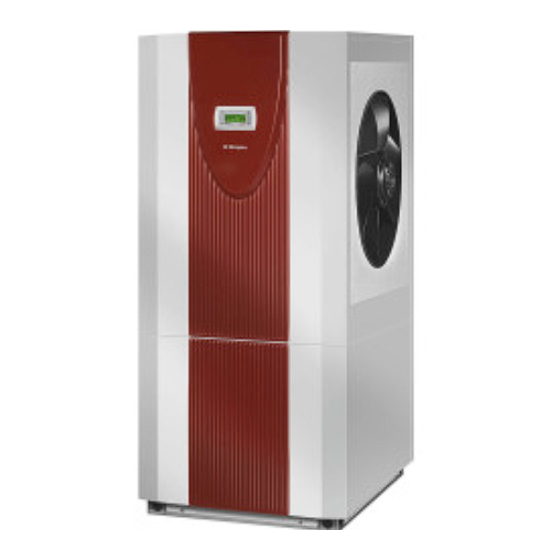
Luft/wasser wärmepumpe für innenaufstellung
Vorschau ausblenden Andere Handbücher für LI 20TE:

Werbung

Verfügbare Sprachen

Verfügbare Sprachen

LI 20TE
LI 24TE
LI 28TE
Luft/Wasser-
Wärmepumpe für
Innenaufstellung
Bestell-Nr. / Order no. / N
Air-to-Water
Heat Pump for
Indoor Installation
o
de commande : 452160.66.03
Montage- und
Gebrauchsanweisung
Installation and
Operating Instructions
Instructions d'installation
et d'utilisation
Pompe à chaleur
air-eau pour
installation
intérieure
FD 9109

Werbung

loading

Inhaltszusammenfassung für Dimplex LI 20TE

  • Seite 1 LI 20TE LI 24TE LI 28TE Montage- und Gebrauchsanweisung Installation and Operating Instructions Instructions d’installation et d’utilisation Luft/Wasser- Air-to-Water Pompe à chaleur Wärmepumpe für Heat Pump for air-eau pour Innenaufstellung Indoor Installation installation intérieure Bestell-Nr. / Order no. / N de commande : 452160.66.03...
  • Seite 3: Inhaltsverzeichnis

    9.1 Pflege..............................DE-10 9.2 Reinigung Heizungsseite ........................DE-10 9.3 Reinigung Luftseite ..........................DE-10 10 Störungen / Fehlersuche ......................DE-10 11 Außerbetriebnahme / Entsorgung ..................DE-10 12 Geräteinformation ........................DE-11 13 Garantieurkunde........................DE-13 Anhang / Appendix / Annexes ......................A-I www.dimplex.de DE-1...
  • Seite 4: Bitte Sofort Lesen

    Bitte sofort lesen 1.3 Gesetzliche Vorschriften und Richtlinien 1.1 Wichtige Hinweise Diese Wärmepumpe ist gemäß Artikel 1, Abschnitt 2 k) der EG- Richtlinie 2006/42/EC (Maschinenrichtlinie) für den Gebrauch im ACHTUNG! häuslichen Umfeld bestimmt und unterliegt damit den Anforde- Für den Betrieb und die Wartung einer Wärmepumpe sind die rechtlichen rungen der EG-Richtlinie 2006/95/EC (Niederspannungsrichtli- Anforderungen des Landes einzuhalten, in dem die Wärmepumpe nie).
  • Seite 5: Verwendungszweck Der Wärmepumpe

    Reif auf dem Verdampfer an und verschlechtert die Wärmeü- Filtertrockner bertragung. Eine ungleichmäßige Anlagerung stellt dabei keinen Verflüssiger Mangel dar. Der Verdampfer wird durch die Wärmepumpe nach Bedarf automatisch abgetaut. Je nach Witterung können dabei Expansionsventil Dampfschwaden am Luftausblas entstehen. Verdichter www.dimplex.de DE-3...
  • Seite 6: Schaltkasten

    3.2 Schaltkasten 4.3 Wärmemengenzähler WMZ Der Schaltkasten befindet sich in der Wärmepumpe. Nach Ab- 4.3.1 Allgemeine Beschreibung nahme der unteren Frontabdeckung und dem Lösen der sich rechts oben befindenden Befestigungsschraube kann der Der Wärmemengenzähler (WMZ 25/32) dient dazu, die angege- Schaltkasten herausgeklappt werden.
  • Seite 7: Transport

    Nach dem Transport ist die Transportsicherung im Gerät am Kondensat nicht direkt in Klärbecken und Gruben einleiten. Die Boden beidseitig zu entfernen. aggressiven Dämpfe sowie eine nicht frostfrei verlegte Konden- satleitung können die Zerstörung des Verdampfers zur Folge ha- ben. www.dimplex.de DE-5...
  • Seite 8: Schall

    6.3 Schall Um Körperschallübertragungen ins Heizsystem zu vermeiden, empfiehlt es sich, die Wärmepumpe mit einem flexiblen Schlauch an das Heizsystem anzubinden. Verwendete Luftkanäle sind schalltechnisch von der Wärme- pumpe zu entkoppeln, um eine Körperschallübertragung auf die Kanäle zu vermeiden. Montage 7.1 Allgemein An der Wärmepumpe sind folgende Anschlüsse herzustellen: Zu-/Abluft...
  • Seite 9: Mindestheizwasserdurchsatz

    „geschützter Lage“ (z.B. in einer Mauernische oder unter dem Balkon) montieren nicht in der Nähe von Fenstern, Türen, Abluftöffnungen, Außenleuchten oder Wärmepumpen anbringen zu keiner Jahreszeit direkter Sonneneinstrahlung aussetzen Fühlerleitung: Länge max. 40 m; Adernquerschnitt min. 0,75 mm²; Außendurchmesser des Kabels 4-8 mm. www.dimplex.de DE-7...
  • Seite 10: Montage Der Anlegefühler

    7.5 Elektrischer Anschluss 7.4.3 Montage der Anlegefühler Die Montage der Anlegefühler ist nur notwendig, falls diese im 7.5.1 Allgemein Lieferumfang der Wärmepumpe enthalten, aber nicht eingebaut sind. Bei der Inbetriebnahme sind die länderspezifischen sowie die Die Anlegefühler können als Rohranlegefühler montiert oder in einschlägigen VDE-Sicherheitsbestimmungen, insbesondere die Tauchhülse des Kompaktverteilers eingesetzt werden.
  • Seite 11: Inbetriebnahme

    Fluss des Heizwassers behindern könnten, geöffnet sein. Der Luftansaug-/-ausblasweg muss frei sein. Die Drehrichtung des Ventilators muss der Pfeilrichtung ent- sprechen. Die Einstellungen des Wärmepumpenmanagers müssen gemäß seiner Gebrauchsanweisung an die Heizungsanlage angepasst sein. Der Kondensatablauf muss sichergestellt sein. www.dimplex.de DE-9...
  • Seite 12: Reinigung / Pflege

    Reinigung / Pflege 9.3 Reinigung Luftseite Luftkanäle, Verdampfer, Lüfter und Kondensatablauf sind vor der 9.1 Pflege Heizperiode von Verunreinigungen (Blätter, Zweige usw.) zu rei- nigen. Dazu ist die Wärmepumpe an der Frontseite zuerst unten Vermeiden Sie zum Schutz des Lackes das Anlehnen und Able- und dann oben zu öffnen.
  • Seite 13: Geräteinformation

    12 Geräteinformation Geräteinformation für Luft/Wasser-Heiz-Wärmepumpen LI 20TE - LI 24TE Typ- und Verkaufsbezeichnung LI 20TE LI 24TE Bauform Schutzart nach EN 60 529 für Kompaktgerät bzw. Heizteil IP 21 IP 21 Aufstellungsort Innen Innen Leistungsangaben Temperatur-Betriebseinsatzgrenzen: Heizwasser-Vorlauf / -Rücklauf °C / °C...
  • Seite 14: Geräteinformation Für Luft/Wasser-Heiz-Wärmepumpen Li 28Te

    Geräteinformation für Luft/Wasser-Heiz-Wärmepumpen LI 28TE Typ- und Verkaufsbezeichnung LI 28TE Bauform Schutzart nach EN 60 529 für Kompaktgerät bzw. Heizteil IP 21 Aufstellungsort Innen Leistungsangaben Temperatur-Betriebseinsatzgrenzen: Heizwasser-Vorlauf / -Rücklauf °C / °C bis 58 / ab 18 Luft °C -25 bis +35 Heizwasser-Temperaturspreizung bei A7 / W35 9,9 / 2,4...
  • Seite 15: Garantieurkunde

    Bei einer Haftung nach § 478 BGB wird die Haftung des Lieferers auf die Servicepauschalen des Liefe- rers als Höchstbetrag beschränkt. Glen Dimplex Deutschland GmbH Garantieurkunde Systemtechnik Eine Verlängerung der Garantie auf 36 Monate für Heizungs-Wärme- (Warmwasser-Wärmepumpen, Heizungs-Wärmepumpen, pumpe und zentrale Wohnungslüftungsgeräte ab Inbetriebnahme-...
  • Seite 16 D-14...
  • Seite 17 9.1 Maintenance ............................EN-10 9.2 Cleaning the Heating System ......................EN-10 9.3 Cleaning the Air System ........................EN-10 10 Faults / Trouble-Shooting ......................EN-10 11 Decommissioning/Disposal ....................EN-10 12 Device Information ........................EN-11 Anhang / Appendix / Annexes ......................A-I www.dimplex.de EN-1...
  • Seite 18: Please Read Immediately

    Please Read 1.3 Legal Regulations and Immediately Directives This heat pump is designed for use in a domestic environment according to Article 1, Paragraph 2 k) of EC directive 2006/42/EC 1.1 Important Information: (machinery directive) and is thus subject to the requirements of EC directive 2006/95/EC (low-voltage directive).
  • Seite 19: Purpose Of The Heat Pump

    The Controllers evaporator is defrosted automatically by the heat pump as re- Filter dryer quired. Steam may be emitted from the air outlet depending on Liquifier the atmospheric conditions. Expansion valve Compressor www.dimplex.de EN-3...
  • Seite 20: Switch Box

    3.2 Switch Box 4.3 Thermal energy meter WMZ The switch box is located in the heat pump. It can be swung out 4.3.1 General description after removing the lower front cover and loosening the fastening screw located in the upper right-hand corner. The thermal energy meter (WMZ 25/32) is used for measuring The switch box contains the supply connection terminals, as well the quantity of thermal energy supplied.
  • Seite 21: Transport

    To prevent solid-borne sound from being transmitted to the heat- ing system, we recommend connecting the heat pump to the heating system using a flexible hose. Installed air ducts should be sound-isolated from the heat pump to prevent the transmission of solid-borne sound to the ducts. www.dimplex.de EN-5...
  • Seite 22: Installation

    Installation 7.1 General Information The following connections need to be established on the heat pump: Fresh and exhaust air Flow and return flow of the heating system Condensate outflow Temperature sensor Power supply 7.2 Air Connection ATTENTION! Do not restrict or block the area around the air intake or outlet. ATTENTION! Only operate the heat pump with the air ducts connected.
  • Seite 23: Temperature Sensor

    The temperature sensors to be connected to the heat pump manager must correspond to the sensor characteristic curve illustrated in Fig.7.1 on pag. 7. The only exception is the external temperature sensor included in the scope of supply of the heat pump (see Fig.7.2 on pag. 7) www.dimplex.de EN-7...
  • Seite 24: Installing The Strap-On Sensor

    7.5 Electrical connection 7.4.3 Installing the strap-on sensor It is only necessary to mount the strap-on sensors if they are 7.5.1 General included in the scope of supply of the heat pump but have not yet been installed. During start-up, observe the respective national safety The strap-on sensors can be fitted as pipe-mounted sensors or regulations and the applicable VDE safety regulations, installed in the immersion sleeve of the compact manifold.
  • Seite 25: Start-Up

    The ventilator must turn in the direction indicated by the ar- row. The settings of the heat pump manager must be adapted to the heating system in accordance with the controller’s oper- ating instructions. Ensure the condensate outflow functions. www.dimplex.de EN-9...
  • Seite 26: Maintenance / Cleaning

    Maintenance / Cleaning 9.3 Cleaning the Air System Air ducts, evaporator, ventilator and condensate outflow should 9.1 Maintenance be cleaned of contamination (leaves, twigs, etc.) before the heat- ing period. Do this by opening the front of the heat pump. The To protect the paintwork, avoid leaning or putting objects on the bottom should be opened first followed by the top.
  • Seite 27: Device Information

    12 Device Information Device information for air-to-water heat pumps (heating only) LI 20TE - LI 24TE Type and order code LI 20TE LI 24TE Design Degree of protection according to EN 60 529 for compact devices IP 21 IP 21...
  • Seite 28 Device information for air-to-water heat pumps (heating only) LI 28TE Type and order code LI 28TE Design Degree of protection according to EN 60 529 for compact devices IP 21 and heating components Installation location Indoors Performance data Operating temperature limits: Heating water flow/return flow °C / °C Up to 58 / above 18...
  • Seite 29 9.1 Entretien .............................FR-10 9.2 Nettoyage côté chauffage........................FR-11 9.3 Nettoyage côté air..........................FR-11 10 Défaillances/recherche de pannes ..................FR-11 11 Mise hors service / mise au rebut................... FR-11 12 Informations sur les appareils ....................FR-12 Anhang / Appendix / Annexes ......................A-I www.dimplex.de FR-1...
  • Seite 30: Lire Immédiatement

    A lire immédiatement ! 1.2 Utilisation conforme Cet appareil ne doit être employé que selon les conditions d'utili- 1.1 Importantes informations sation prévues par le fabricant. Toute autre utilisation est consi- dérée comme non conforme. Les descriptions accompagnant les produits doivent également être prises en compte. Toute modifi- ATTENTION ! cation ou transformation de l'appareil est à...
  • Seite 31: Utilisation De La Pompe À Chaleur Pour Économiser De L'énergie

    Une accumulation irrégulière de givre n'est pas considérée comme un défaut. L’évaporateur est dégivré automatiquement par la pompe à chaleur selon les besoins. En fonction des conditions météorologiques, des nua- ges de vapeur peuvent apparaître au niveau de l’évacuation d’air. www.dimplex.de FR-3...
  • Seite 32: Fournitures

    Fournitures 3.2 Boîtier électrique Le boîtier électrique est monté dans la pompe à chaleur. Le boî- 3.1 Appareil de base tier électrique peut être rabattu après avoir retiré l’habillage fron- tal inférieur et dévissé la vis de fixation se trouvant en haut à La pompe à...
  • Seite 33: Calorimètre Wmz

    Transport ATTENTION ! ATTENTION ! Lors du transport, l’angle d’inclinaison de la pompe à chaleur ne doit pas Avant la mise en service, il faut enlever la protection de transport. dépasser 45° (quel que soit le sens). www.dimplex.de FR-5...
  • Seite 34: Emplacement De Montage

    Emplacement de 6.3 Bruit montage Pour éviter les transmissions de bruit dans le système de chauf- fage, il est recommandé de raccorder la pompe à chaleur au sys- tème de chauffage à l'aide d’un tuyau flexible. 6.1 Remarques d’ordre général Les conduits d’air utilisés doivent être découplés de la pompe à...
  • Seite 35: Raccordement Côté Chauffage

    (maillage maxi. 5 µm). Il n'est pas possible d'empêcher totalement la formation de cal- caire dans les installations de chauffage à eau chaude. Sa quan- tité est cependant négligeable pour les installations ayant des températures aller inférieures à 60°C. www.dimplex.de FR-7...
  • Seite 36: Sonde De Température

    7.4 Sonde de température 7.4.2 Montage de la sonde de température extérieure Les sondes de températures suivantes sont déjà montées ou doivent être installées en plus : La sonde de température doit être placée de telle sorte qu’elle puisse détecter la plupart des influences atmosphériques sans sonde de température extérieure (R1) fournie que les valeurs mesurées ne soient faussées : sonde de température retour (R2) intégrée...
  • Seite 37: Circuit De Distribution D'eau Chaude Sanitaire

    (cou- rant de déclenchement suivant spécifications techniques). Lors du raccordement, garantir la rotation à droite du champ magnétique de l'alimentation de charge L1 ; L2 ; L3. www.dimplex.de FR-9...
  • Seite 38: Mise En Service

    Mise en service ATTENTION ! L'exploitation de la pompe à chaleur à de plus basses températures système est susceptible d'entraîner sa défaillance totale. Après une 8.1 Remarques d’ordre général coupure de courant de longue durée, exécuter la procédure mentionnée ci-dessus pour la mise en service. Pour garantir une mise en service en règle, cette dernière doit être effectuée par un service après-vente agréé...
  • Seite 39: Nettoyage Côté Chauffage

    Le démontage et l’accrochage des panneaux de façade s’effec- tue comme décrit au chapitre 4. L’utilisation d’objets pointus et durs est à éviter lors du nettoyage afin d´empêcher toute détérioration de l’évaporateur et de la cuve de condensats. www.dimplex.de FR-11...
  • Seite 40: Informations Sur Les Appareils

    12 Informations sur les appareils Informations sur les pompes à chaleur air/eau pour chauffage LI 20TE - LI 24TE Désignation technique et commerciale LI 20TE LI 24TE Forme Type de protection selon EN 60 529 pour app. compact ou élt. de chauffe...
  • Seite 41 Selon le lieu d'installation, la valeur mesurée peut varier de 16 db(A) max. 5. Voir déclaration de conformité CE 6. Le circulateur de chauffage et le régulateur de la pompe à chaleur doivent toujours être prêts à fonctionner. www.dimplex.de FR-13...
  • Seite 42 FR-14...
  • Seite 43 Anhang / Appendix / Annexes Maßbilder / Dimension Drawings / Schémas cotés..............A-II 1.1 Maßbild / Dimension Drawing / Schéma coté LI 20TE ................A-II 1.2 Maßbild / Dimension Drawing / Schéma coté LI 24TE / LI 28TE............A-III Diagramme / Diagrams / Diagrammes ..................A-IV 2.1 Kennlinien / Characteristic curves / Courbes caractéristiques LI 20TE ..........A-IV...
  • Seite 44: Maßbilder / Dimension Drawings / Schémas Cotés

    1 Maßbilder / Dimension Drawings / Schémas cotés 1.1 Maßbild / Dimension Drawing / Schéma coté LI 20TE A-II...
  • Seite 45: Maßbild / Dimension Drawing / Schéma Coté Li 24Te / Li 28Te

    1.2 Maßbild / Dimension Drawing / Schéma coté LI 24TE / LI 28TE www.dimplex.de A-III...
  • Seite 46: Diagramme / Diagrams / Diagrammes

    2 Diagramme / Diagrams / Diagrammes 2.1 Kennlinien / Characteristic curves / Courbes caractéristiques LI 20TE A-IV...
  • Seite 47: Kennlinien / Characteristic Curves / Courbes Caractéristiques Li 24Te

    2.2 Kennlinien / Characteristic curves / Courbes caractéristiques LI 24TE www.dimplex.de...
  • Seite 48: Kennlinien / Characteristic Curves / Courbes Caractéristiques Li 28Te

    2.3 Kennlinien / Characteristic curves / Courbes caractéristiques LI 28TE A-VI...
  • Seite 49: Stromlaufpläne / Circuit Diagrams / Schémas Électriques

    3 Stromlaufpläne / Circuit Diagrams / Schémas électriques 3.1 Steuerung / Control / Commande www.dimplex.de A-VII...
  • Seite 50: Last / Load / Charge

    3.2 Last / Load / Charge A-VIII...
  • Seite 51: Anschlussplan / Circuit Diagram / Schéma Électrique

    3.3 Anschlussplan / Circuit Diagram / Schéma électrique www.dimplex.de A-IX...
  • Seite 52: Legende / Legend / Légende

    3.4 Legende / Legend / Légende Brücke EVU-Sperre: muss eingelegt werden, wenn Utility block bridge: Must be inserted if no utility Pont de blocage de la société d'électricité : à insé- kein EVU-Sperrschütz vorhanden ist blocking contactor is present rer si aucun contacteur de blocage de la société ( Kontakt offen = EVU-Sperre).
  • Seite 53 A higher voltage must on no account be connected! ATTENTION ! Une faible tension est appliquée aux bornes enfichables J1 à J7, J9 à J11, J24 et au bornier X3. Ne jamais appliquer une tension plus élevée !. www.dimplex.de A-XI...
  • Seite 54: Hydraulische Prinzipschemen / Hydraulic Plumbing Diagrams / Schémas Hydrauliques

    4 Hydraulische Prinzipschemen / Hydraulic Plumbing Diagrams / Schémas hydrauliques 4.1 Monoenergetische Anlage mit zwei Heizkreisen / Mono energy system with two heating circuits/Installation monoénergétique avec deux circuits de chauffage A-XII...
  • Seite 55: Monoénergétique Avec Deux Circuits De Chauffage

    4.2 Monoenergetische Anlage mit zwei Heizkreisen und Warmwasserbereitung / Mono energy system with two heating circuits and domestic hot water preparation /Installation monoénergétique avec deux circuits de chauffage et production d´eau chaude www.dimplex.de A-XIII...
  • Seite 56: Bivalente Anlage Mit Zwei Heizkreisen Und Warmwasserbereitung / Bivalent System With Two Heating Circuits And Domestic Hot Water Preparation / Installation Bivalente Avec Deux Circuits De Chauffage Et Production D´eau Chaude

    4.3 Bivalente Anlage mit zwei Heizkreisen und Warmwasserbereitung / Bivalent system with two heating circuits and domestic hot water preparation / Installation bivalente avec deux circuits de chauffage et production d´eau chaude A-XIV...
  • Seite 57: Legende / Legend / Légende

    Sonde sur mur extérieur Rücklauffühler Return flow sensor Sonde sur circuit de retour Warmwasserfühler Hot water sensor Sonde sur circuit d’eau chaude sanitaire Temperaturfühler 2. Heizkreis Temperature sensor for heating circuit 2 Sonde de température 2ème circuit de chauffage www.dimplex.de A-XV...
  • Seite 58: Konformitätserklärung / Declaration Of Conformity / Déclaration De Conformité

    5 Konformitätserklärung / Declaration of Conformity / Déclaration de conformité A-XVI...
  • Seite 59 A-XVII...
  • Seite 60 Glen Dimplex Deutschland GmbH Irrtümer und Änderungen vorbehalten. Geschäftsbereich Dimplex Subject to alterations and errors. Am Goldenen Feld 18 Sous réserve d’erreurs et modifications. D-95326 Kulmbach +49 (0) 9221 709 565 www.dimplex.de...

Diese Anleitung auch für:

Li 24teLi 28te452160.66.03