Werbung
Verfügbare Sprachen
Verfügbare Sprachen
Quicklinks
Figure 1a: M701-240 ( -KO ) Surface Mount
Output Module with 240V Relay Contacts
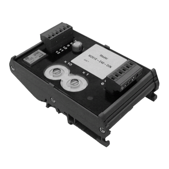
Figure 1b: M701-240-DIN Din Rail Mounted
Output Module with 240V Relay Contacts.
TO MOUNT, LOCATE LUG OVER TOP
OF RAIL AND ROTATE THE MODULE
DOWN TO CLIP INTO PLACE.
TO REMOVE, PUSH UPWARDS, AND
ROTATE TOP OF MODULE AWAY
FROM RAIL.
Figure 2: Module Wiring
NOTE: Wiring is the same for M701-240 ( -KO ) and M701-240-DIN
Relay 1, N/O
7
Relay 2, N/C
8
Ground
9
Ground
10
Relay 2, N/C
11
Relay 1, N/O
12
8 9
6 7
5
4
3
2
1
0
TENS
ROTARY DECADE ADDRESS SWITCHES
Notes:
1. If short circuit isolation is not required, then the loop output should
be wired to terminal 5 rather than terminal 2. Terminal 5 is internally
connected directly to terminal 4.
2. In order to meet the requirements of European Safety Standards,
ensure that all cables carrying voltages in excess of 48V are suitably
fused.
N200-93-01
M701-240, M701-240-KO
INSTALLATION INSTRUCTIONS FOR MAINS
LOOP CABLE SCREEN TERMINAL
Loop -, Out
1
Loop +, Out - See Note 1
2
Loop -, In
3
Loop +, In
4
Loop +, Out - See Note 1
5
T6 - Not Connected
6
8 9
6 7
10
11
5
4
12
3
13
2
14
1
15
0
UNITS
DoP Ref: 0786-CPD-20341
EN54-17: 2005
EN54-18: 2005
Pittway Tecnologica S.r.l,
Via Caboto 19/3,
0786 07
34147 Trieste, Italy
Notifier by Honeywell, Caburn House, 2B Brooks Road, Lewes, East Sussex, BN7 2BY, UK
SWITCHING OUTPUT MODULES
This manual is intended as a quick reference installation guide. Please refer
to the control panel installation manual for detailed system information.
GENERAL INFORMATION
The M700+ series of modules are a family of microprocessor controlled
interface devices permitting the monitoring and/or control of auxiliary
devices. The M701-240, M701-240-KO and M701-240-DIN are output
modules, providing 250VAC 5A rated voltage free contacts, both normally
open and normally closed.
SPECIFICATIONS
Operating Voltage Range:
Maximum Standby Current (µA): 275µA - No Communication
Fault Current:
Coil Activation/Deactivation Current: 76mA Maximum for 12mS
Relay Contact Rating:
Maximum rated continuous current with the isolator closed (I
Maximum rated isolator current (under short circuit) (I
Maximum leakage current (I
Maximum series impedance with the isolator closed (Z
Operating Temperature:
Humidity:
Dimensions M701-240 and M701-240-KO: 134mm(H) x 139mm(W) x 40mm(D)
Dimensions M701-240-DIN:
Weight M701-240 and M701-240-KO: 195g
Weight M701-240-DIN:
Maximum Wire Gauge
INSTALLATION
Note: These modules must only be connected to control panels using
compatible proprietary analogue addressable communication
protocols for monitoring and control.
Disconnect loop power before installing modules or sensors.
High voltages may be present on terminals 7 to 12.
M701-240 and M701-240 -KO
1. The M701-240 ( -KO ) includes a custom low profile surface-mounting
box with several options for fixing centres. To access all fixing points,
and the rear cable entry knock out, the circuit board must be removed.
It is held in place by two screws through the circuit board. Ensure that
these screws are replaced when refitting the circuit board.
2. If rear cable entry is not required, the box has several cover drill points
permitting the entry of cables using suitable glands.
3. Wiring to the M701-240 ( -KO ) is made via two 6 way terminal strips
on the module circuit board, capable of supporting conductors up to
1.5mm². See figure 2 for connections.
4. An earthing terminal is provided in the surface mount box for connection
of the loop cable screen, if used, to ensure continuity. See figure 1a.
M701-240-DIN
1. M701-240-DIN mounts onto standard 35mm x 7.5mm "Top Hat" DIN
rail. It must be mounted in a suitable cabinet meeting the applicable
safety standards.
2. Wiring to the M701-240-DIN is via plug in type terminals capable of
supporting conductors up to 2.5mm². See figure 2 for connections.
Ensure that the correct terminals are used for the loop and
switched voltage as damage may result from incorrect usage.
For both modules, the address is selected by means of rotary decade
address switches (see figure 2), accessed at the front of the module. A
screwdriver should be used to rotate the wheels to select the desired
address. (Note: The number of addresses available will be dependent on
panel capability, check the panel documentation for information on this.)
Short Circuit Isolators
All M700+ series modules are provided with short circuit monitoring and
isolators on the intelligent loop. If required the isolators may be wired out of
the loop to facilitate the use of the modules on high current loaded loops, for
example if sounders are used. To achieve this, the loop out positive should
be wired to terminal 5 rather than terminal 2.
M701-240-DIN
AND
15 to 30VDC (Min 19.5VDC to ensure LED
operation - M701-240-KO 17.5VDC)
445µA - Communication LED blink enabled - 5 secs
375µA - Read 16 sec. LED blink 8 sec
8.8mA (Yellow LED illuminated)
5A, at 30VDC, 5A at 250VAC
max) with the isolator open (isolated state): 15mA
L
-20°C to 60°C
5% to 95% Relative Humidity
127mm(H) x 76mm(W) x 48mm(D) (Including terminals)
140g
1.5mm² - M701-240 (-KO), 2.5mm² - (-DIN)
CAUTION
WARNING
E N G L I S H
max): 1A
c
max): 1A
s
max): 170 m ohm at 15Vdc
c
I56-1763-014
Werbung

Verwandte Anleitungen für Honeywell NOTIFIER M701-240


Inhaltszusammenfassung für Honeywell NOTIFIER M701-240
- Seite 4 M701-240, M701-240-KO M701-240-DIN D E U T S C H INSTALLATIONSANLEITUNG FÜR DIE STEUERMODULE FÜR NETZSCHALTSPANNUNG Diese Kurzbedienungsanleitung ermöglicht einen schnelle Überblick zur Installation der Module. Für detaillierte Informationen lesen Sie bitte in der Installationsanleitung Abbildung 1a: M701-240 ( -KO ) Steuermodul der Brandmelderzentrale nach.