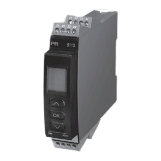
PR electronics 9113 Bedienungsanleitung
Temperatur / ma wandler
Vorschau ausblenden
Andere Handbücher für 9113:
- Handbuch (147 Seiten) ,
- Produkthandbuch (46 Seiten) ,
- Produkthandbuch (41 Seiten)

Verwandte Anleitungen für PR electronics 9113


Inhaltszusammenfassung für PR electronics 9113
- Seite 1 9 1 1 3 T e m p e r a t u r / m A W a n d l e r N o . 9 1 1 3 V 1 0 4 - D E P r o d u k t v e r s i o n : 9 1 1 3 - 0 0 4 S I G N A L S T H E B E S T...
- Seite 2 PR electronics A/S tilbyder et bredt program af analoge og digitale signalbehandlingsmoduler til industriel automation. Programmet består af Isolatorer, Displays, Ex-barrierer, Temperaturtransmittere, Universaltransmittere mfl. Vi har modulerne, du kan stole på i selv barske miljøer med elektrisk støj, vibrationer og temperaturud- sving, og alle produkter opfylder de strengeste internationale stan- darder.
-
Seite 3: Inhaltsverzeichnis
Flussdiagram, Erweiterte Einstellungen (ADV.SET) .... 24 Scrollender Hilfstext im Display Zeile 3 ......25 Appendix ................26 IECEx Installation Drawing ..........27 ATEX Installation Drawing ..........30 FM Installation Drawing ........... 33 Safety Manual ..............35 9113 - Product Version 9113-004... -
Seite 4: Warnung
Installation, Montage und Demontage von Leitungen. Fehlersuche im Gerät. reparaturen des gerätes und Austausch von sicherungen dürfen nur von pr electronics A/s vorgenommen werden. WArnung Die Frontplatte des Gerätes darf nicht geöffnet werden, weil hier durch die Kontakte zur Kontaktierung des Frontdisplays 4501 beschädigt werden können. -
Seite 5: Empfang Und Auspacken
Sollten Zweifel bezüglich der richtigen Handhabung des Gerätes bestehen, sollte man mit dem Händler vor Ort Kontakt aufnehmen. Sie können aber auch direkt mit pr electronics gmbh, www.prelectronics.dk Kontakt aufnehmen. Der Einsatz von verdrillter Leitung ist nicht erlaubt außer die Enden sind mit Aderendhülsen versehen. -
Seite 6: Kalibrierung Und Justierung
Wasser leicht angefeuchtet ist. hAfTung In dem Umfang, in welchem die Anweisungen dieses Handbuches nicht genau eingehalten werden, kann der Kunde PR electronics gegenüber keine Ansprüche geltend machen, welche ansonsten entsprechend der eingegange- nen Verkaufsvereinbarungen existieren können. -
Seite 7: Eg-Konformitätserklärung
60079-15 : 2005 und en 60079-26 : 2007 ATeX-zertifikat: kemA 07ATeX0148 X Zulassungsstelle: dekrA Quality B.v. (0344) utrechtseweg 310, 6812 Ar Arnhem p.o. Box 5185, 6802 ed Arnhem The netherlands Rønde, 10. August 2012 Kim Rasmussen Unterschrift des Herstellers 9113 - Product Version 9113-004... -
Seite 8: Erweiterte Merkmale
Stromsignalen. • Der 9113 wurde entwickelt und zertifiziert für SIL 2-Anwendungen entsprechend den Anforderungen der Richtlinie IEC 61508. Technische merkmale • 1 grüne und 2 rote Leuchtdioden in der Front des Gerätes zeigen den normalen Betrieb und Fehlfunktionen an. • 2,6 kVAC galvanische Trennung zwischen Eingang, Ausgang und Versorgung. 9113 - Product Version 9113-004... -
Seite 9: Anwendungen
Typ 5910Ex/ 5913Ex separat bestellen! Versorgung über Power Rail zone 0, 1, 2, 20, 21, 22, m1 & cl. I/II/III, div. 1 zone 2 / cl. 1, div. 2, gr. A-d oder sicheres Bereich gr. A-g 9113 - Product Version 9113-004... -
Seite 10: Pr 4501 Display / Programmierfront
Punkt = nicht SIL-verriegelt. Zeile 4 zeigt auch den Kommunikationsstatus an. • Der Zugriff auf die Programmierung kann mit der Eingabe eines Passwortes blockiert werden. Das Passwort wird im Messumformer gespeichert, um den höchsten Grad an Schutz gegen nicht autorisierte Änderungen der Konfiguration sicherzustellen. montage / Installation • Stecke das 4501 auf die Front des 9113. 9113 - Product Version 9113-004... -
Seite 11: Bestellangaben 9113
......... ≤ 0,4 s Kalibrierungstemperatur ......20...28°C Genauigkeit: Der höhere Wert der allgemeinen Werte oder Grundwerte: Allgemeine Werte Eingangs- Absolute Temperatur- Genauigkeit koeffizient ≤ ±0,1% d. Messsp. ≤ ±0,01% d. Messsp. / °C Alle 9113 - Product Version 9113-004... - Seite 12 Relative Luftfeuchtigkeit ......< 95% RF (nicht kond.) Abmessungen, ohne Frontdisplay (HxBxD) .. 109 x 23,5 x 104 mm Abmessungen, mit Frontdisplay (HxBxD) ... 109 x 23,5 x 116 mm Schutzart ............. IP20 Gewicht ............250 g / 265 g mit 4501 9113 - Product Version 9113-004...
- Seite 13 Vergleichsstellenkompensation (CJC): über externen Sensor in der Anschlussklemme 5910 ....... 20...28°C ≤ ± 1°C -20...20°C og 28...70°C ≤ ± 2°C über internen CJC-Sensor ....±(2,0°C + 0,4°C * ∆t) ∆t = interne Temperatur - Umgebungstemperatur 9113 - Product Version 9113-004...
- Seite 14 Versorgungsspannungsänderung....< 0,005% d. Messspanne / V statusrelais in sicheres Bereich: Max. Spannung ........... 125 VAC / 110 VDC Max. Strom ..........0,5 AAC / 0,3 ADC Max. Leistung ..........62,5 VA / 32 W 9113 - Product Version 9113-004...
- Seite 15 FM us ............3038279-C GOST Ex funktionaler sicherheit: exida, Cert No..........PREl 070902 P0002 C03.01 SIL 2-zertifiziert über Full Assessment gemäß IEC 61508 FMEDA-Bericht - www.prelectronics.de d. messspanne = der momentan gewählten Messspanne 9113 - Product Version 9113-004...
-
Seite 16: Konfiguration Der Sensorfehlerüberprüfung
Sensor Kurzschluss SE.SH Siehe Bedingungen oben Interner CJC-Fühler defekt oder Test des internen CJC-Fühlers CJ.ER Temp. außerh. des Bereichs** Defekte oder fehlende CJC- CJC-Anschlussklemmen-Fehler - überprüfe CJC- CJ.CE Anschlussklemme, Temperatur Klemmenblock außerhalb des zulässigen Bereiches 9113 - Product Version 9113-004... - Seite 17 Einige Fehler können nur durch Wegnahme der Versorgungsspannung zurück gesetzt werden. ** Fehler wird entweder durch Durchschalten der Grundeinstellungen oder durch Wegnahme der Versorgungsspannung zurück gesetzt! Fehler greift nur bei TE-Eingang. *** Fehler wird durch Durchschalten der Grundeinstellungen zurück gesetzt. 9113 - Product Version 9113-004...
-
Seite 18: Anschlüsse
5910Ex (Kanal 1) / 5913Ex (Kanal 2) separat bestellen. Ausgänge Strom 2-Draht-Umformer Strom 2-Draht-Umformer (aktiver Ausgang) (passiver Ausgang) (aktiver Ausgang) (passiver Ausgang) 11 12 13 14 11 12 13 14 11 12 13 14 11 12 13 14 9113 - Product Version 9113-004... -
Seite 19: Blockdiagramm
BlockdIAgrAmm 9113 - Product Version 9113-004... -
Seite 20: Signalfehler- Und Kabelfehler Erkennung Ohne Frontdisplay
9113 - Product Version 9113-004... -
Seite 21: Konfiguration / Bedienung Der Funktionstasten
Dokumentation für das Flussdiagramm. grundsätzliches Bei der Konfiguration des 9113 werden Sie durch alle Parameter geleitet und Sie können die Einstellungen wählen, welche zur Applikation passt. Für jedes Menü existiert ein scrollender Hilfetext welcher automatisch in der 3. Zeile im Display gezeigt wird. -
Seite 22: Hauptfunktionen
Eingangssignals eine Prozesskalibrierung durchgeführt werden. Ein niedriges Eingangssignal (0% nicht unbedingt nötig) muss anliegen und der aktuelle Wert wird übernommen. Dann wird ein höherer Wert (nicht unbedingt 100%) eingelesen. Wenn Sie die Kalibrierung akzeptieren, wird das Gerät mit den 9113 - Product Version 9113-004... - Seite 23 Power Rail: Im Menü ”Rail” können Sie wählen, ob Sensor-Fehler an die zentrale Überwachung im Power Control Unit PR 9410 weitergegeben werden sollen. safety Integrity level (sIl): Für Details sehen Sie bitte im Sicherheitshandbuch (Safety Manual) nach. 9113 - Product Version 9113-004...
- Seite 24 Passwort gesichert ist TC.K SENSOR TC.TYPE Txt 10 Txt 18 Txt 36 Roter Text bedeutet Sicher- heitsparameter in einer SIL Konfiguration. Siehe Sicherheitshandbuch (Safety Manual) für Details. Fortsetzung auf Seite 96 Flussdiagramm ADV.SET ADV.SET Txt 2 9113 - Product Version 9113-004...
- Seite 25 999.9 999.9 -199.9 -199.9 Konfiguration von 150.0 Kanal 2 identisch zum OUT.LO OUT.HI RESP. Zum Normal-Zustand 1.0 Txt 14 Txt 15 Txt 35 Kanal 1 9113 - Product Version 9113-004...
-
Seite 26: Flussdiagram, Erweiterte Einstellungen (Adv.set)
LOCK 9999 OPEN Bestätigung der SIL-Konfiguration 2007 LOCK SETUP EN.SIL NEW.PAS CONFIG SIL.OK Txt 17 Txt 34 Txt 55 Txt 38 ....9113 - Product Version 9113-004... -
Seite 27: Scrollender Hilfstext Im Display Zeile 3
FLASH Memory Fehler - Konfiguration kontrollieren Wähle NAMUR NE43 Upscale bei Fehler [47] Ungültige Konfiguration oder Version [48] Hardware-Fehler [49] CJC Sensor-Fehler - Geräte-Temperatur kontrollieren [50] CJC Fehler - CJC Stecker Terminal kontrollieren [51] Keine Kommunikation 9113 - Product Version 9113-004...